I've been testing the one shot library, and the zero crossing detector, everything seems to be working perfectly!
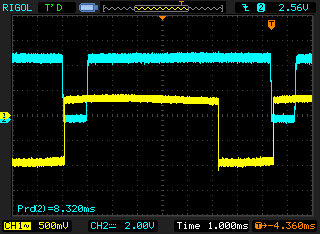
The blue trace is the output of the zero crossing detector, the yellow is the one shot output from OC0B.
The blue goes low when the AC input is near or at 0 volts. This allows for the detection of both rising and falling crossings, though the distinction does not matter for this project.
The yellow trace goes low to activate the opto-isolator and triac. Because the triac will not de-energize until a zero crossing (0V potential across its terminals), in order to have variable control we must activate the triac some variable time after the zero crossing.
Because the AVR is triggering on the falling edge of the zero crossing, we can have the opto disabled before the zero crossing rises, and not have to worry about the triac being activated early.
However, because the PID will require a steady timebase, we'll need to test if the fluctuating 60hz AC is stable enough to drive the calculations... That would make all of this quite easy, just recalculate the PID value on every INT0!
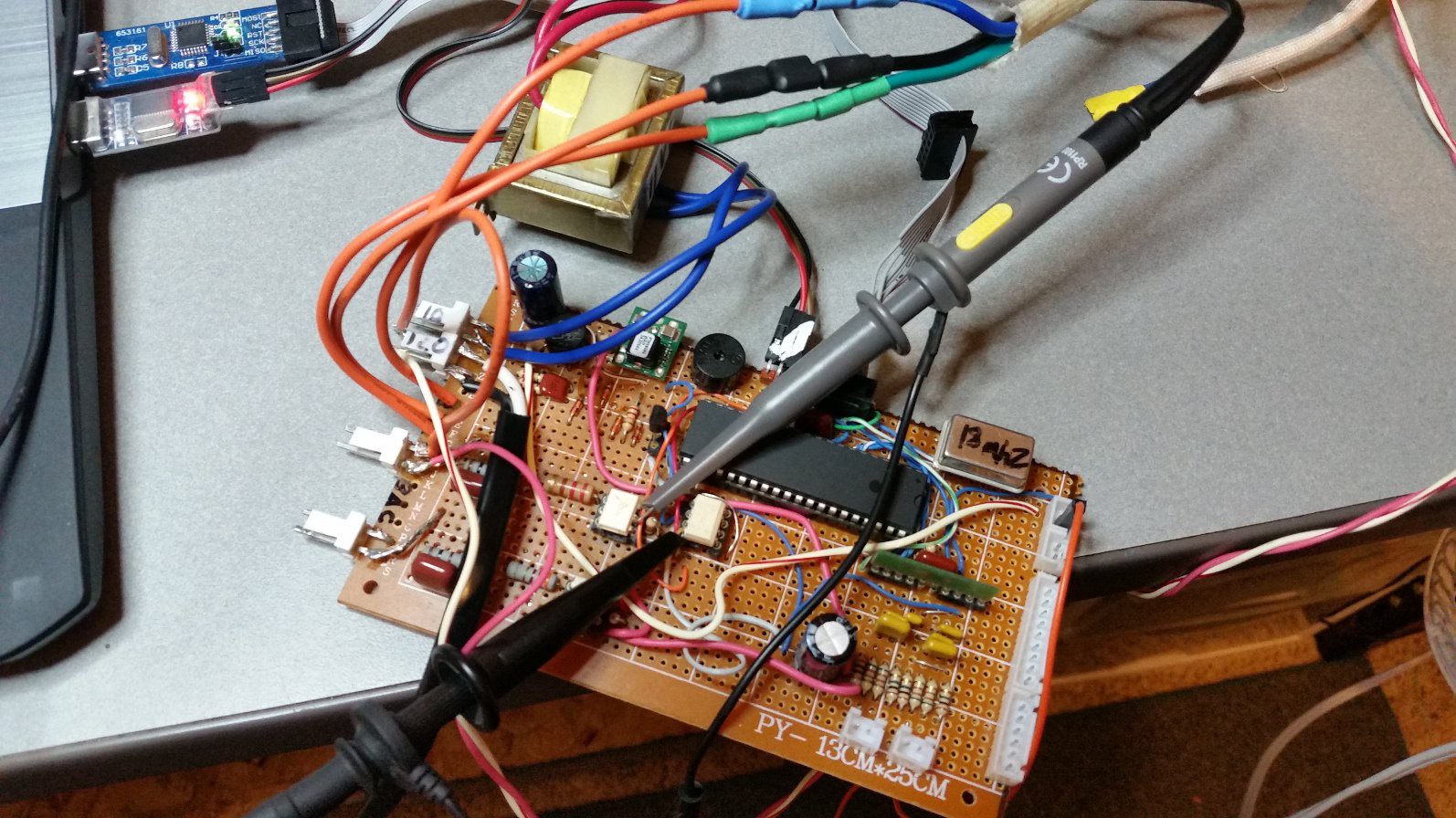
The perfboard prototype! 120VAC is hardwired into the zero crossing circuit. The transformer is a stand-in for the huge toroid in the T-870a, and provides 10vac to the power supply section. The triac in the T-870a is connected via the crimp connectors and orange wires.
With this setup, I was able to both dim an incandescent lamp, and "dim" a fan, as tests. Everything worked flawlessly, though this was a simple test of the one shots and INT0. The real test will come when integrating the PID into the mix.
Discussions
Become a Hackaday.io Member
Create an account to leave a comment. Already have an account? Log In.