 polyfractal
Things have been a bit slow around here. Between work travel, personal events on weekends and waiting for components to arrive, not a whole lot has been happening on the MakerFoundry. My schedule should free up next month, so I'm hopeful updates will resume with good frequency then.
In the meantime, I upgraded the temperature controller on my muffle furnace as a small-yet-useful project.
Fair warning: my main laptop has gone to the great scrapheap in the sky, so I'm stuck with potato camera photos and minimal editing for the foreseeable future. Sorry :(
My furnace -- an eBay special -- is a rather old model. While it can reach the temperatures I need (1000C), it has a very hard time maintaining that temperature. It does leak some heat through the door, which gets measurably hotter than the rest of the furnace. But the main reason is the temperature controller.
The stock controller consists of two main components. First, there is a power selector which switches between low/medium/high power. At first I thought this controlled amperage through the heater coils. But on closer inspection that's too sophisticated. Instead, the selector toggles on successively larger number of coils. Low turns on two coils (8 amps), medium feeds three coils (12 amps) and high turns on all four coils (16 amps).
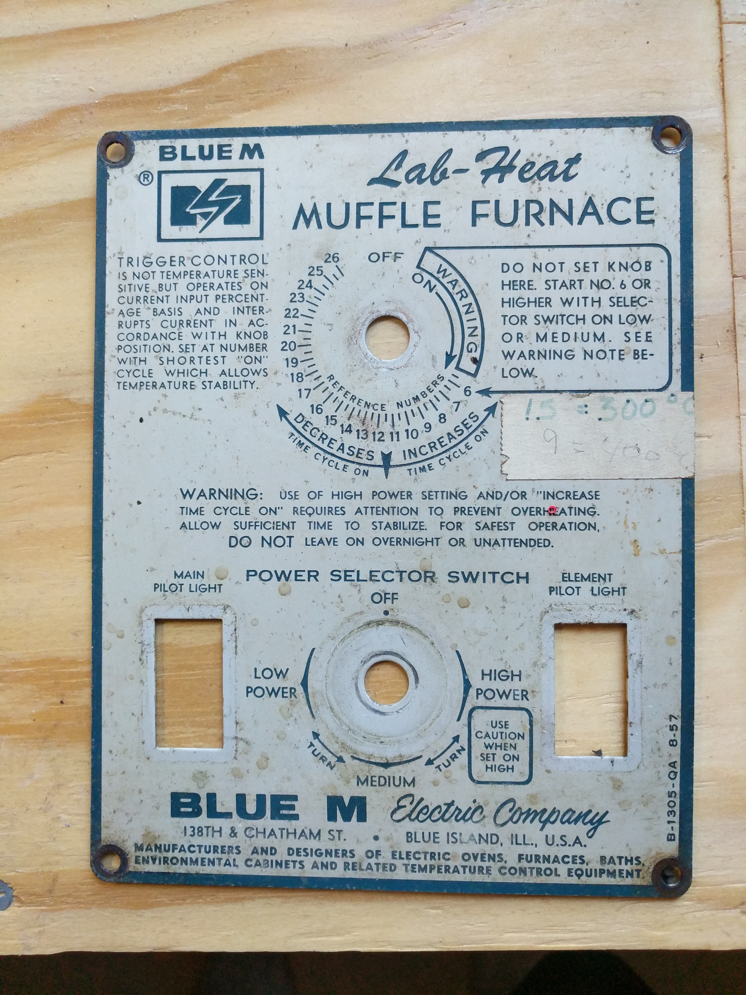
The second component is the temperature controller itself. By rotating a knob, you select the duty cycle of the heaters. Attached to the selector is an AC motor which slowly rotates. While I haven't torn open the selector, I believe this is what's happening: by rotating the knob, you expose more/less of a conductive lead. The motor then slowly wipes across this lead, and the duty cycle is determined by how long the lead is contacted.
Selecting a lower duty exposes less contact area and the heater is off for more per-cycle. Selecting higher duty does the opposite. It's crude, but sorta elegant at the same time. Analog, low frequency PWM.
Unfortunately, it does a crap job maintaining a certain temperature. For whatever reason, there's an upper bound on switching time before it toggles to "always on". At 1000C, I needed a duty cycle somewhere in between the max cycle and "always on". The max cycle time would continuously drop below 1000C, while always-on started to shoot dangerously high. And it's really irritating to babysit the furnace (although you should always be in the same room as it for safety reasons)
PID Upgrade
So, the analog controller had to go. Luckily, it's super simple (and cheap) to buy/install digital PID controllers with a solid-state relay. I picked up an Inkbird 100V and a 40amp SSR and wired it up this weekend. While I was at it, I also installed a new thermocouple since I believe they can wear out over time... and this furnace has definitely seen better days.
Long story short, I didn't electrocute myself and it seems to work!
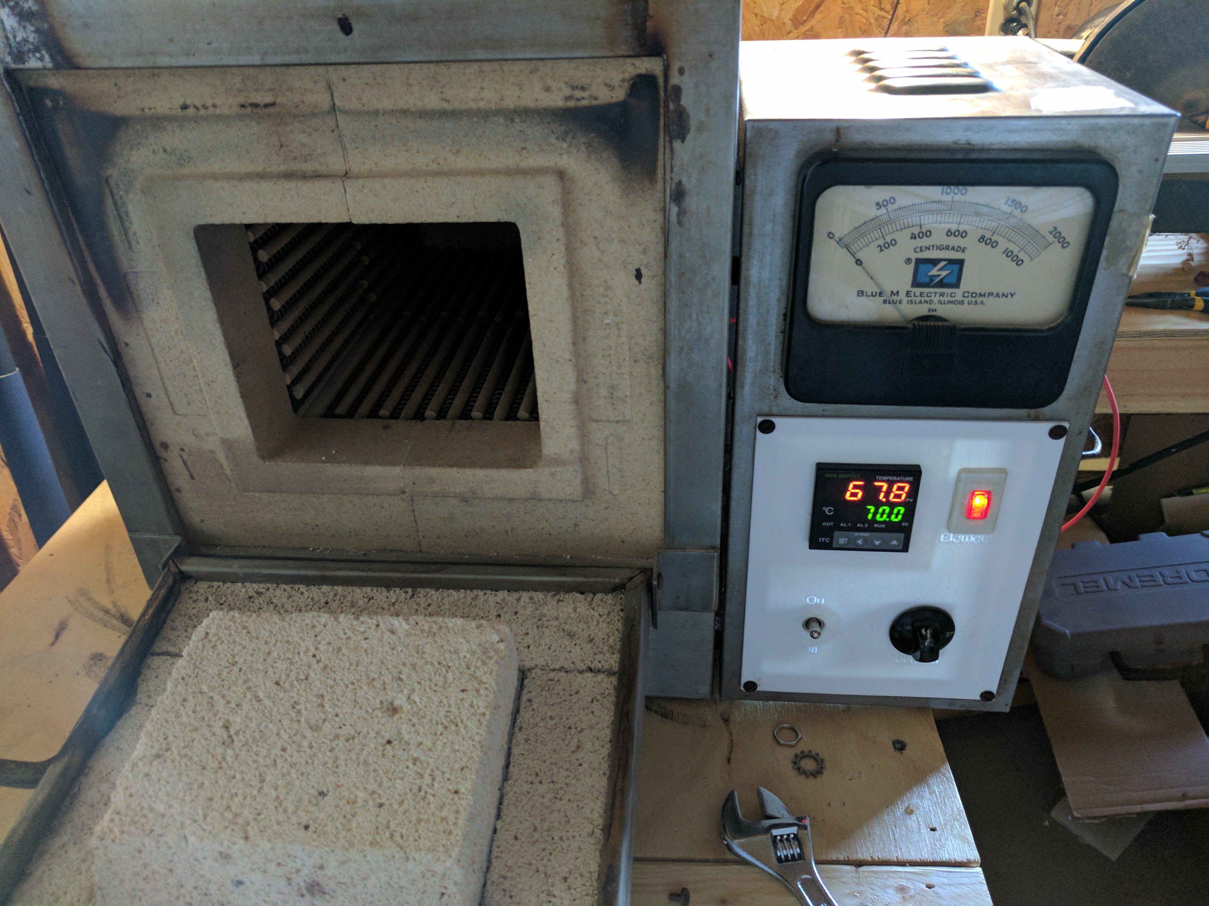
 Here's a view of the front. I printed a faceplate matching the dimensions of the old one, and reused the power-selector and an indicator light. There is, of course, the new digital PID controller as well as a toggle switch to cut power to the whole setup.
The inside is a fair bit uglier. Dealing with 12ga wire sucks, and at some point I gave up having a tidy installation in favor of "just get it working".
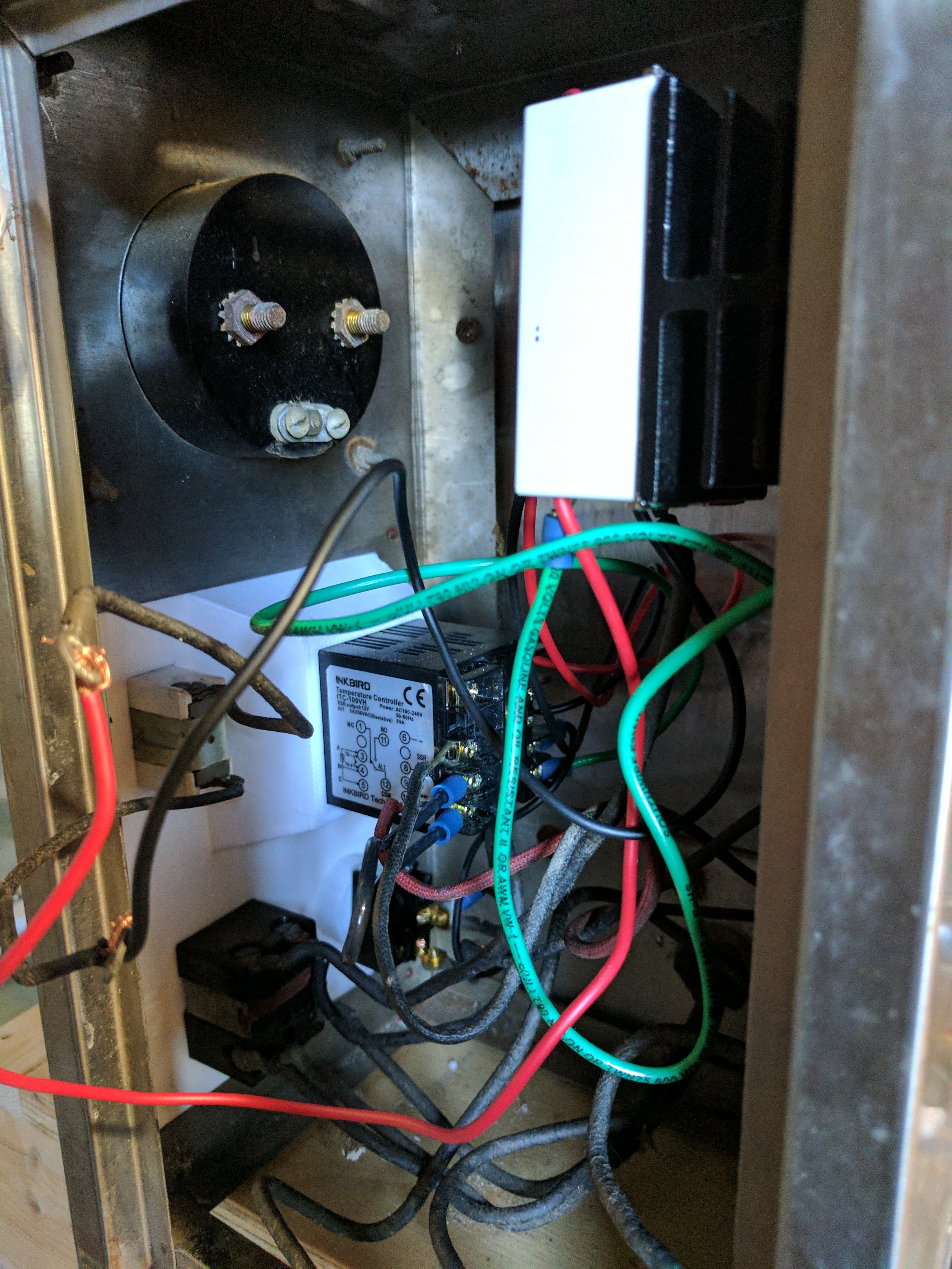 On top you can see the old thermocouple analog meter (now disconnected). Inside the rat's nest of wiring is the PID controller (top right), indicator light (top left), three-way power selector (bottom left) and toggle switch (bottom right).
On the other side is the solid-state relay and heatsink. Below it is a bus-bar connecting to the mains input. I originally planned to wire more into the bus-bar but the 12ga wire was such a hassle I ended up wirnig things together directly at terminals more often than not.
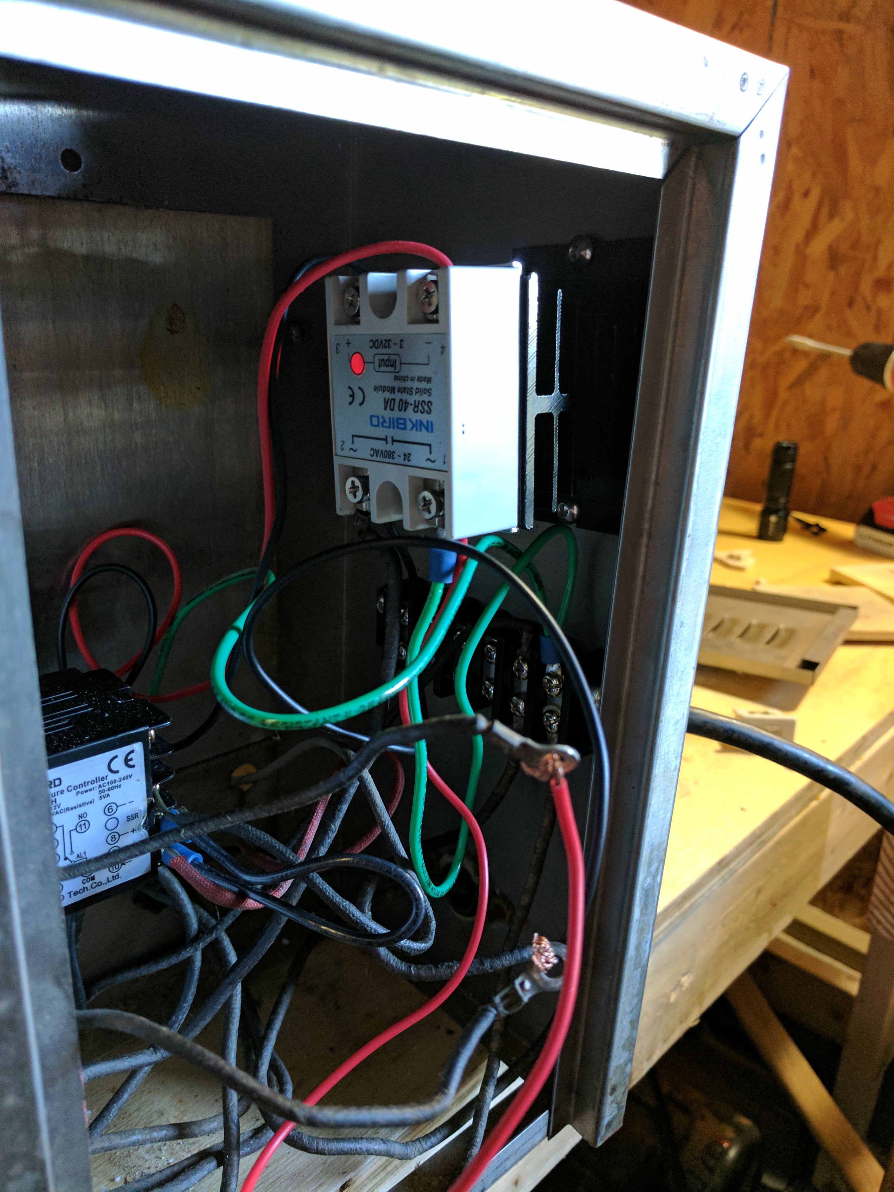
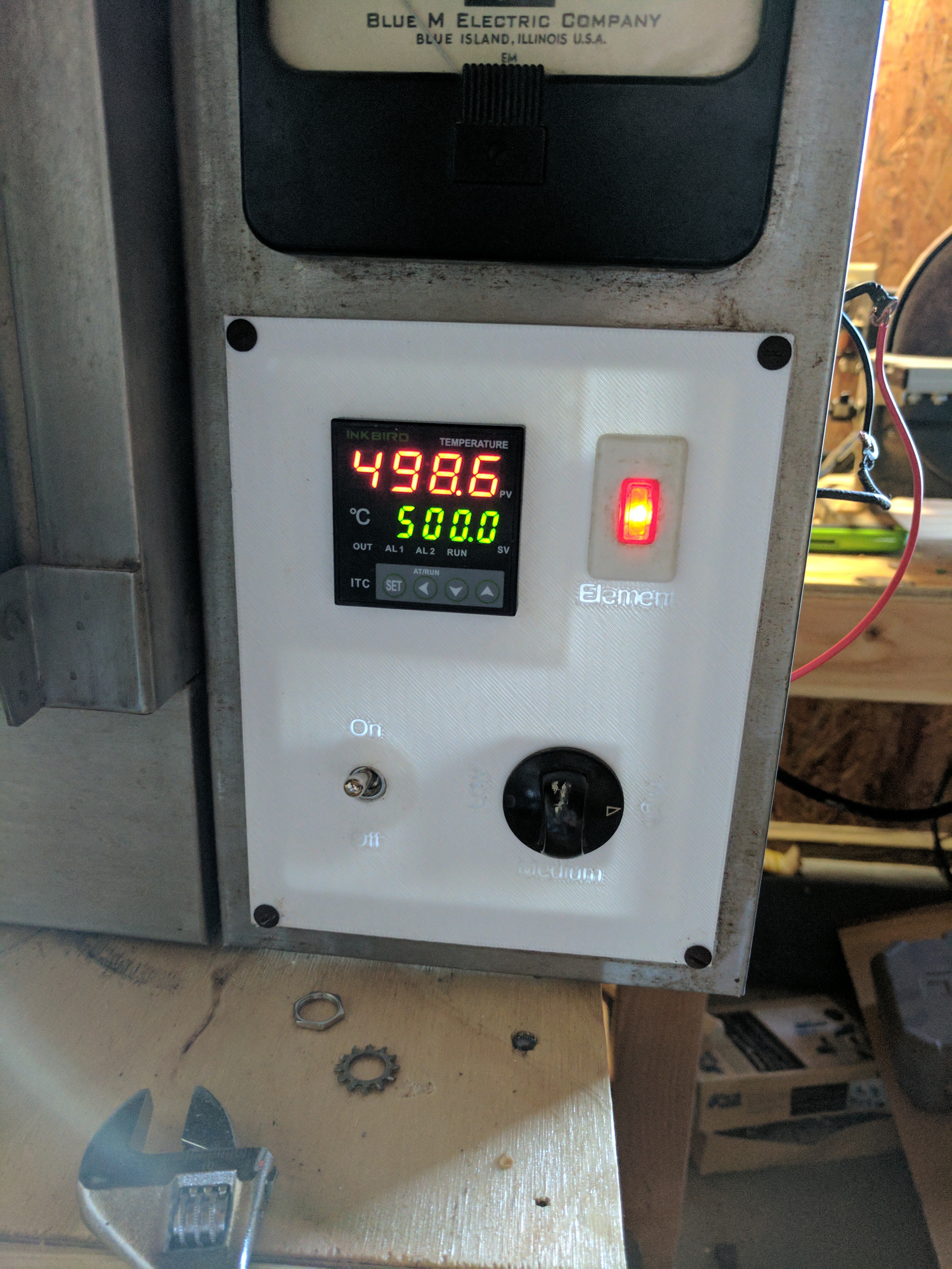
I'm slightly concerned about the SSR's temperature during operation. In a 500C test, the SSR remains loaded for many minutes at a time continuously. The SSR peaked around 45C, and the heatsink hit about 55C. The SSR should be rated to around 80C so there's plenty of wiggle room...assuming the SSR lives up to the datasheet. I may mount the SSR directly to the case (with thermal compound) and mount the heatsink on the opposite side so it can cool in ambient air, rather than the air inside the compartment. That would also leverage the case itself as a heatsink (although the back of the case where the heatsink is mounted does get noticeably hotter).
All in all, I'm pretty happy. There were some silly mistakes along the way, such as the element light illuminating inversely to load (I'm still not sure what's going on there...) but generally it was a smooth upgrade.
The digital PID should do a much better job.
Discussions
Become a Hackaday.io Member
Create an account to leave a comment. Already have an account? Log In.