 Ryan Baron
-
11Step 11
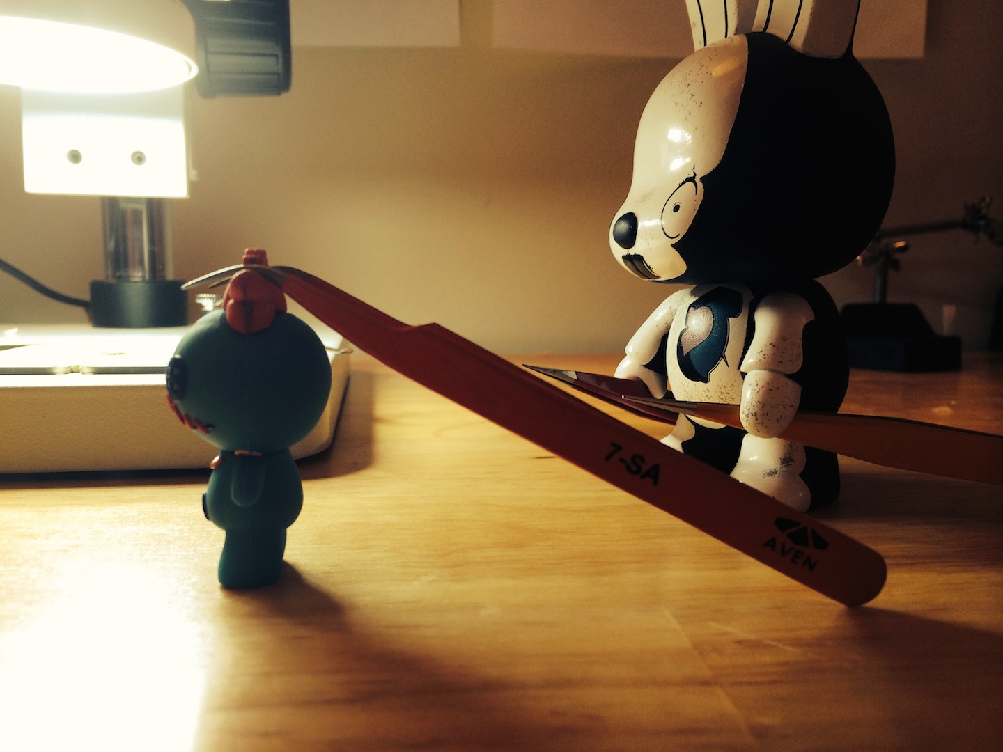
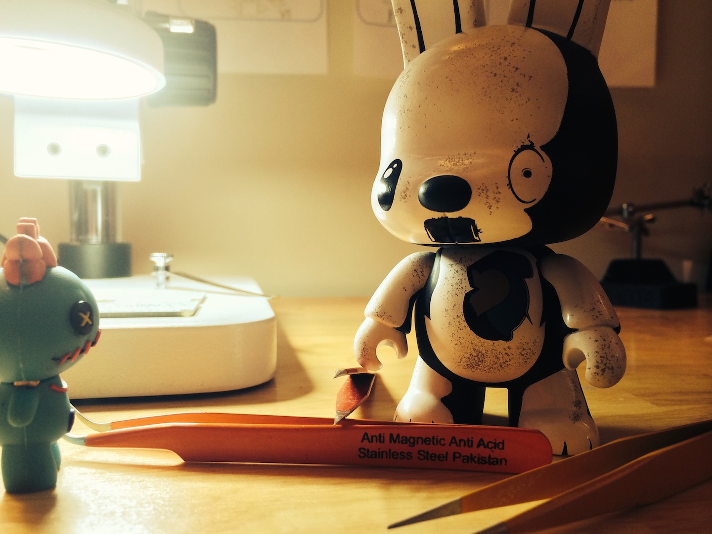
TIME FOR TOOLS
ESD protected tweezers with the super sharp ends are your new best friends. Depending on where your part is located it may be easier to use a curved or straight tweezer. Better have one of each in your holster, cowboy.
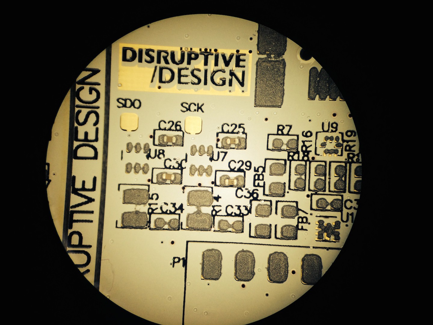
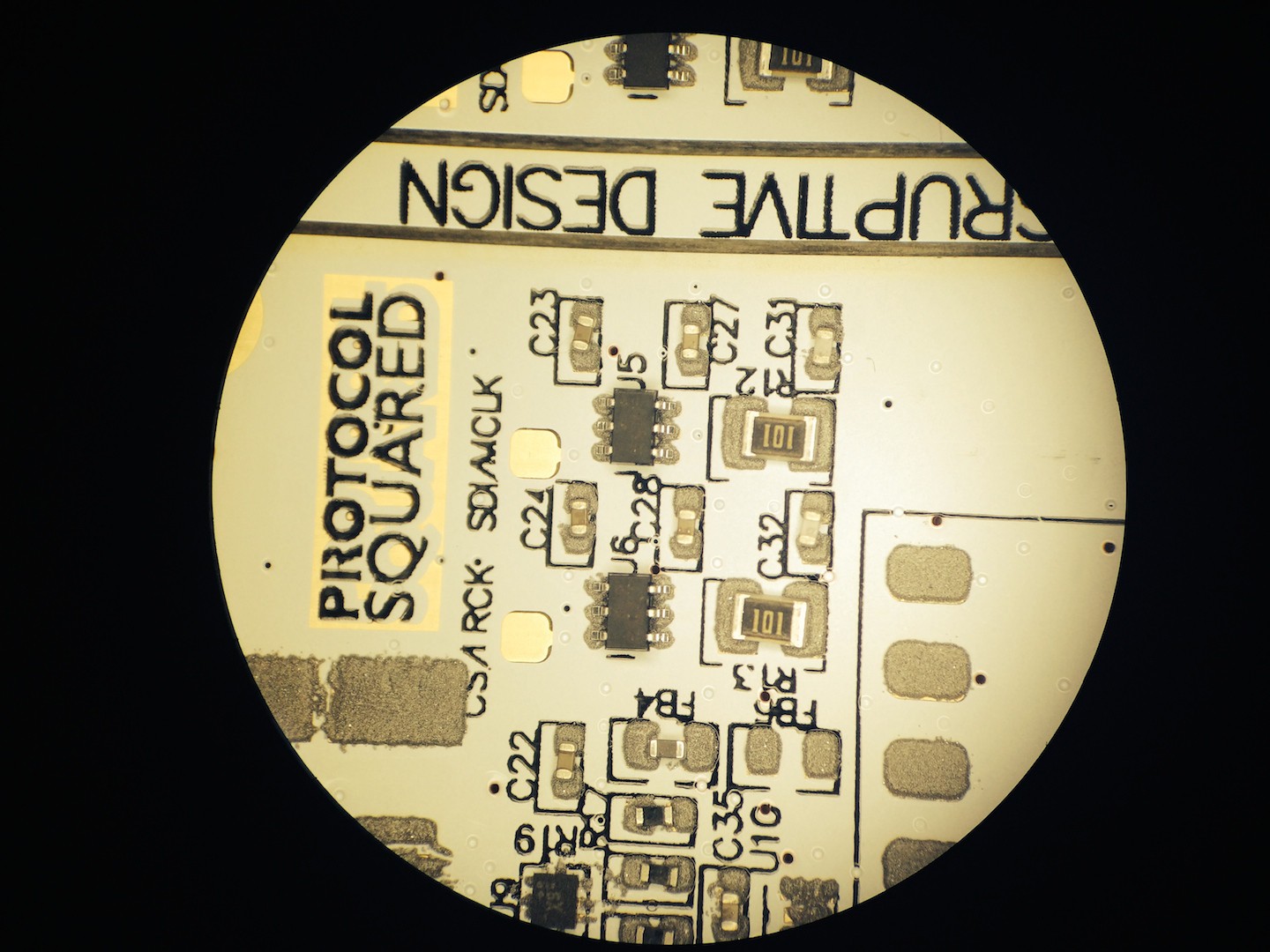
Of course a microscope is helpful. I picked mine up at an electronics market in China for about $50 with LCD view screen. Don't even write that on your customs sheet to get it back to Canada, you'll be explaining "China garage sale" for weeks to customs to get it across the border. Just put $300 and pay the customs charges.
http://www.digikey.ca/product-search/en?vendor=0&k...

http://www.digikey.ca/product-search/en?vendor=0&k...

![]()
![]()
-
12Step 12
COFFEE
Obviously, gotta be right on the edge of shaky and focused.
![]()
![]()
![]() Who's gonna clean this up.
Who's gonna clean this up. -
13Step 13
PLACING PARTS
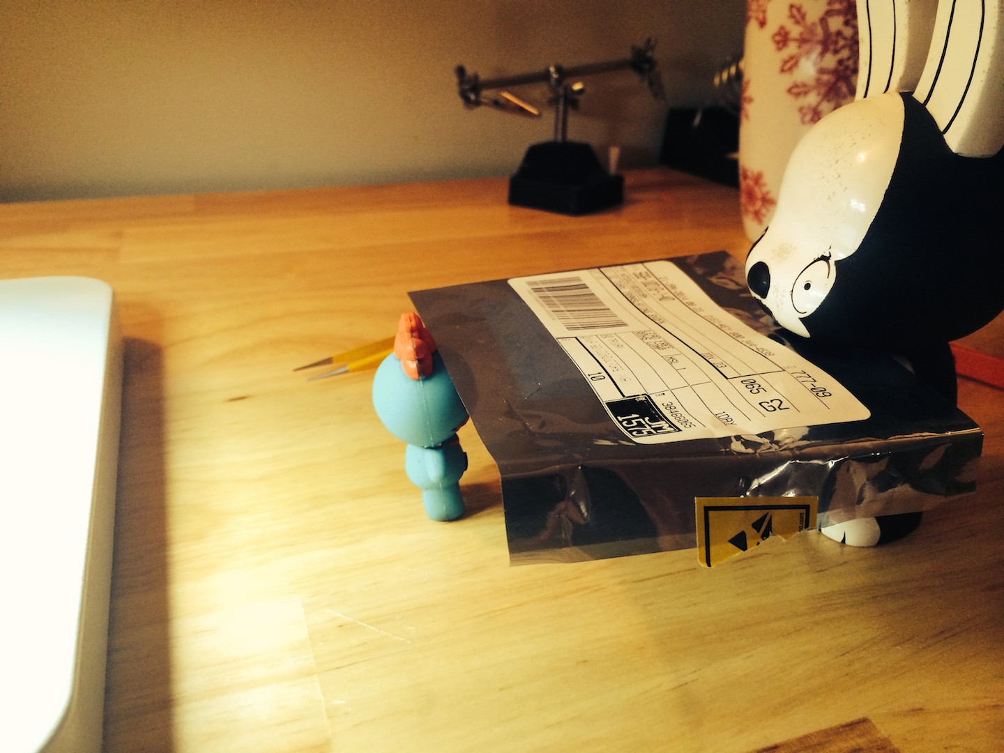
First you get the part.
![]()
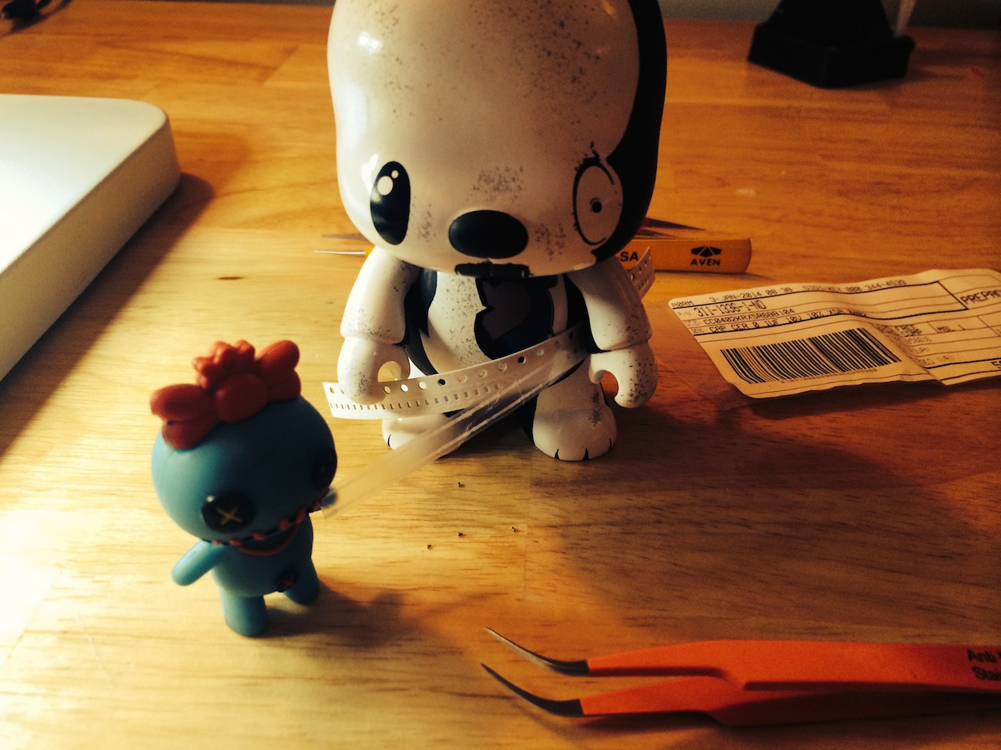
Then you spill it out on your table.
![]()
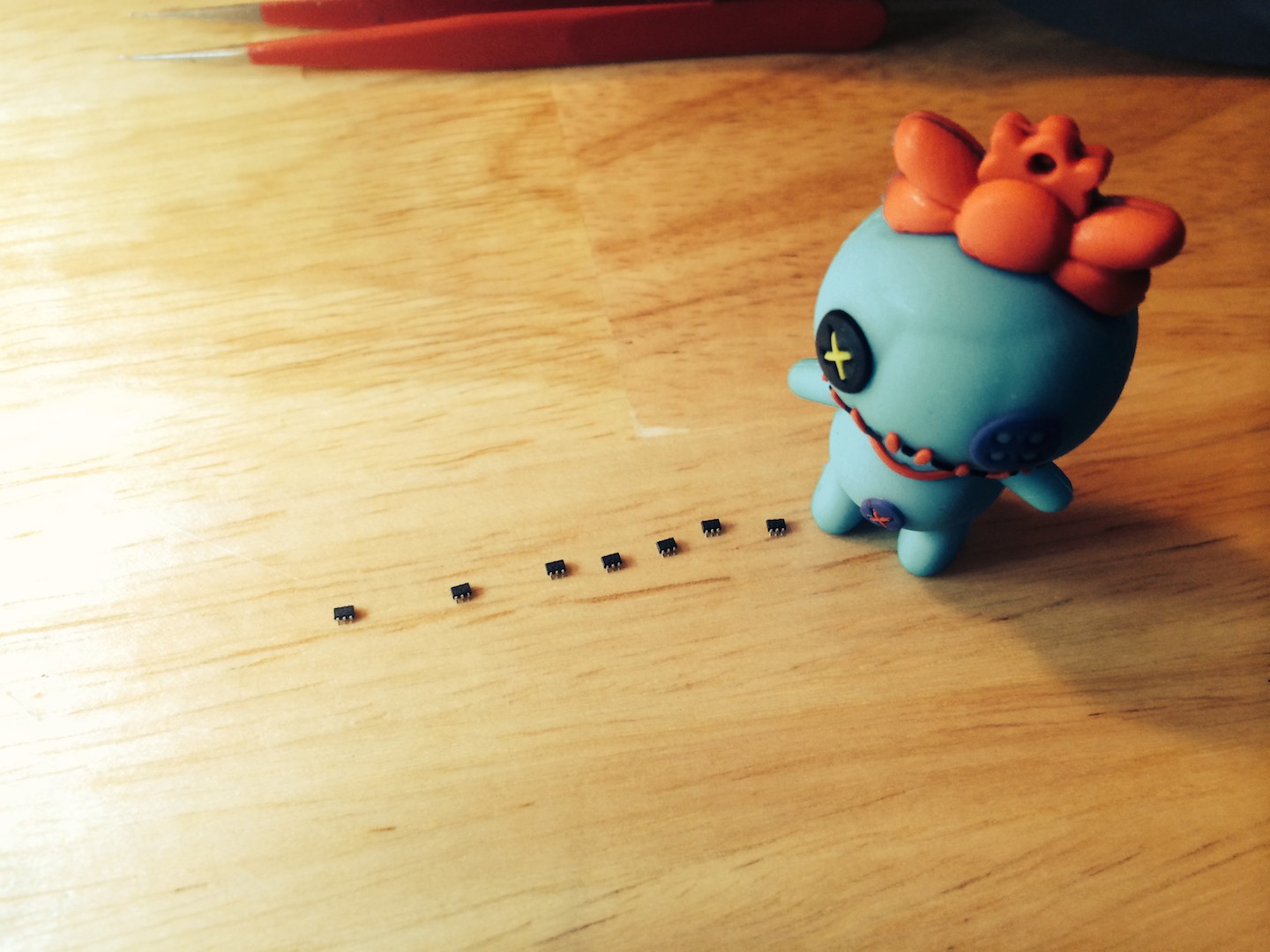
Take the part with your tweezers and place it in the right place. Don't fiddle! And don't try to get it perfectly straight. In reflow the solder will pull the parts straight. Just drop the parts in their spot and give them a gentle tap on top of them to make sure they won't fly off when you're walking to the reflow oven.
![]()
Repeat - forever.
![]()
![]()
They're like pet ants. No you can't keep them.
![]()
-
14Step 14
FOREVER
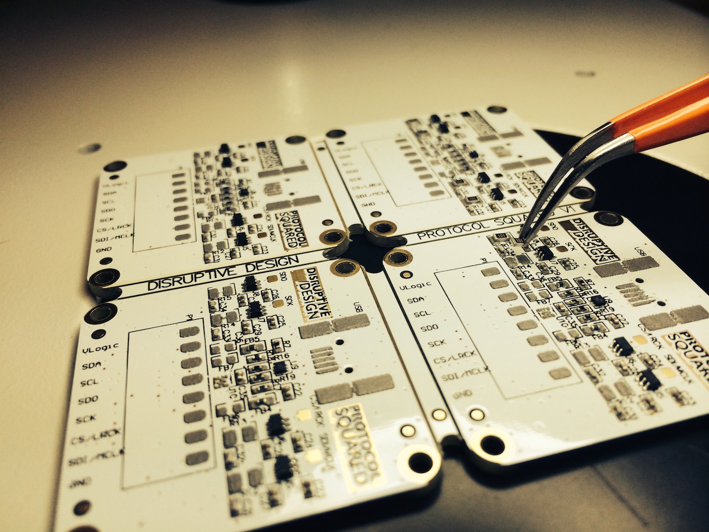
Once forever is up, just keep going on adding parts until Side A is completely done. For these boards it took me about 2 hours per side for each panel including stencil and reflow time.
![]()
You can see in this picture the U5 and U6 components have the solder paste completely mushed together after placing the part. Don't worry if this happens, Reflow is a magical place where solder just finds it's way to where it needs to be. These likely won't even need to be reworked.
![]()
Put all the big parts on last, that way they won't obstruct your tweezers when putting the small parts down.
![]()
-
15Step 15
REFLOW
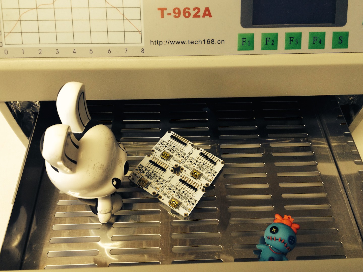
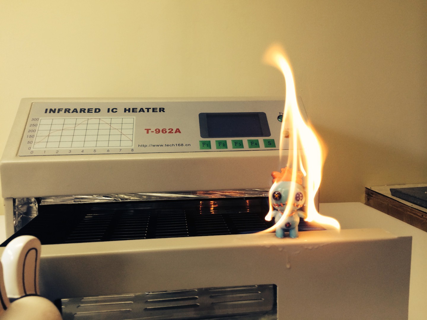
WOOHOOO! The reflow oven I'm using is a T-962A. http://blog.petrockblock.com/2014/01/10/reflow-ove... It's cheap and works perfect for these small board runs.
I'd suggest running the oven outside or in your garage, the solder STINKS and it's leaded. If it was mercury we might have a chance at a long life, but i'm not too sure about lead particulates in my lungs. http://en.wikipedia.org/wiki/Elixir_of_life
Put your board in the center of the rack and select a temperature profile that matches your solder and parts. For us, our solder and the T-962A it was the preset profile 2 that provided the best result.
![]()
![]()
![]()
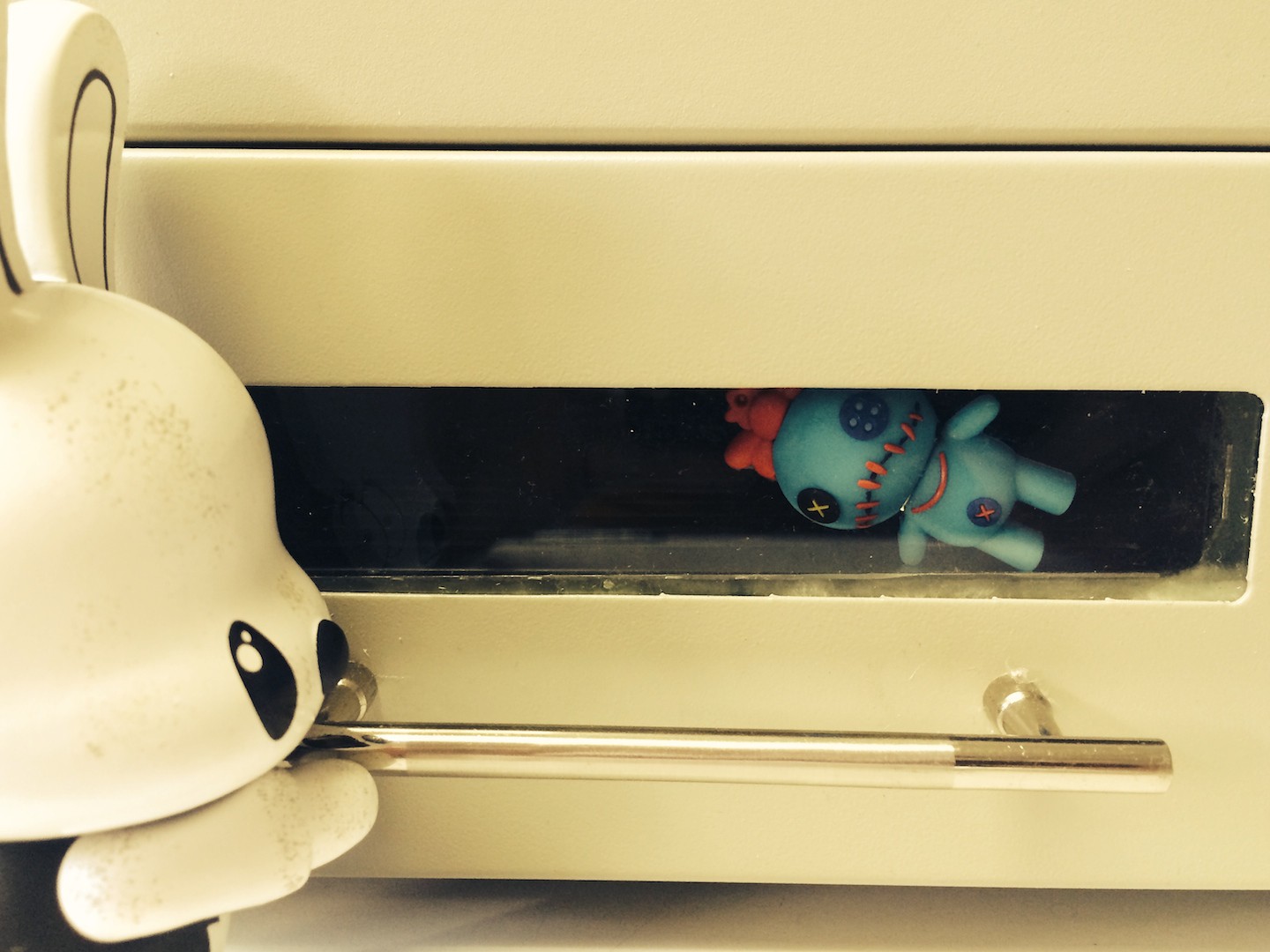
Don't forget to show up to the safety meetings. The boards get HOT.![]() Hug it out and lets get back to work!
Hug it out and lets get back to work!![]()
-
16Step 16
HOW DID WE DO?
Looks good, other than C27 on the left. It's tombstoned. A quick fix. This happens when the part is pulled upwards by the tension of the melted solder. Commonly this happens when the solder melts on one side before it does the other. Note: our U5 and U6 components don't have any bridges! The solder found it's way.
![]()
In high volume production with small footprint parts such as this guy (AKA the bane of my existence):
http://www.digikey.ca/product-detail/en/DMP21D5UFB...
Layout is key to achieving acceptable fallout rates. The PCB pads will heat up to the solder melting point at different rates depending on the thermal mass associated with that area.
If a parts pad of a small part is connected to a pad of a large part in close distance it will take longer to heat up that one pad than the other pads on the footprint. This usually means the small part gets sucked away from the cold pad.
Solution: Be keen about heat distribution in your layouts. Space vias equally from all pads and try to limit the effect other larger parts have on smaller parts by providing enough space between them.
-
17Step 17
REWORK
Fix any parts that did not have a good day.
![]()
-
18Step 18
SIDE B
You're going to need to build a raised holder to stencil side B. This is because the PCBs don't sit flat anymore and they're higher then your standard PCB holders.
I cut this one out of a piece of wood that happily matched the PCB height with a jig saw.
![]()
After applying the paste as shown in the previous steps to side B, you can see that our MCU paste is a bit messy. It's ok, any solder shorts are easy to fix after reflow.
![]()
Lets place the MCU along with the rest of the parts and reflow. In reflow you don't have to worry about the Side A parts falling off, the surface tension of the solder will keep them stuck to the board.
The one thing you do have to do differently this reflow round is prop the panel up off the bed of the oven. I did this by using 4 nuts (bolts & nuts not walnuts), one for each corner of the panel. This prevents the oven bed from placing mechanical force on the side A parts.
![]()
-
19Step 19
REWORK
Some of our MCU pins had solder shorts. This is easy to fix with a soldering iron and a pair of sharp tweezers.
Here's the trick:
Heat up both pins so the solder melts with the iron. Place one prong of the tweezers between the two pins. Pull the tweezer prong out from the component along with the iron at the same time.
The solder bridge will break and you're a happy camper.
Flux tells the solder to behave itself, feel free to get wild with it and soak your solder problems in it. A bit of flux and heat can sometimes fix things right up without anything else.

http://www.digikey.ca/product-search/en?KeyWords=S...
Commonly in Asia the rework team will just use hypodermic needles that you would use for insulin injection and fill them with solder flux. Works good, but it's SCARY having bunch of needles laying all over your workbench when you're a hand talker.
We opted for white solder mask on our boards, just because it looks cool. If you rework or reflow at high temperature it will burn and turn brown at the hot spots. Something to keep in mind.
-
20Step 20
VCUT FUN
Snap the boards at the Vcuts. In volume production they will use a powered machine that looks like this to cut the PCBs. This is one of the reasons why you need to keep parts a minimum distance away from the edge of the PCB or else this thing will be whipping them off like it's making confetti for a wedding.
![]()
![]()
![]()
![]()
![]()
Misadventures of in-house prototyping
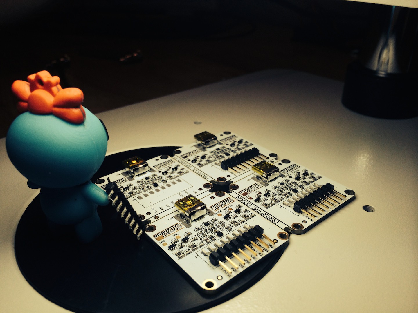
We've put the minions to work stencilling, pasting, populating and reflowing to turn a PCB into a PCBA.


 Who's gonna clean this up.
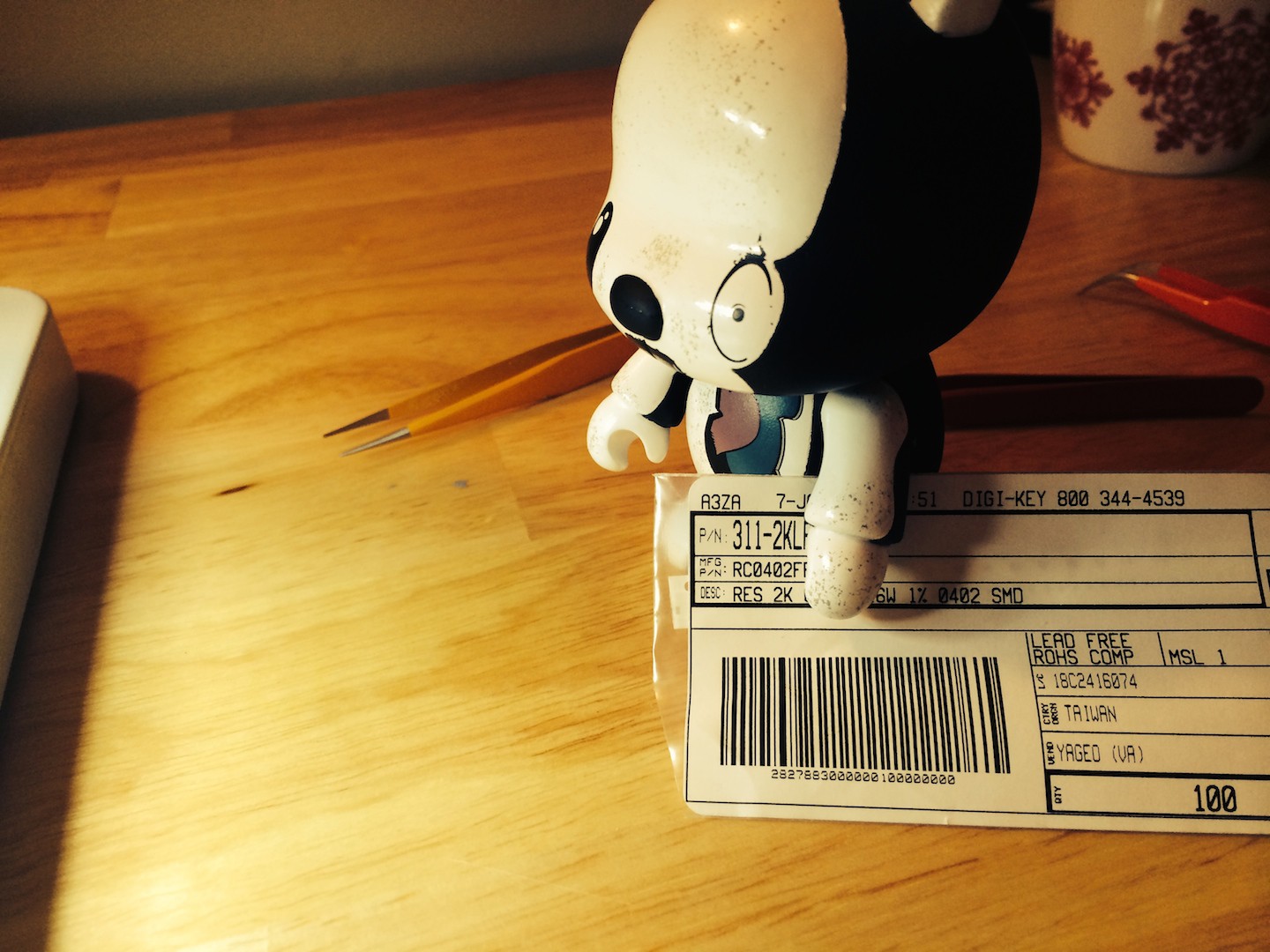


 Hug it out and lets get back to work!


Discussions
Become a Hackaday.io Member
Create an account to leave a comment. Already have an account? Log In.