Things you need
- 2 Arduinos - In this case, I am using DFRduino Uno Rev3 and DFRobot Mega2560
- Jumper Wires
Software serial and UART between Arduinos
The serial port, professionally called Universal Asynchronous Receiver/Transmitter (UART) communication, is generally used to program and debug the Arduino via the USB port. There are multiple sensors and systems that use UART as the main communication method, and sometimes we need to discuss between two Arduinos to share information, workload, and so on.
However, most Arduinos only have one serial port, which is used by the USB connection. Serial communication can only happen between two devices. What can we do now? With a bit of luck, we'll have an Arduino Mega or similar that has up to four serial ports, but if we don't, there still is a solution. A special library has been written that simulates an UART port on other digital pins. There are a few drawbacks, but it generally works.
How to do it
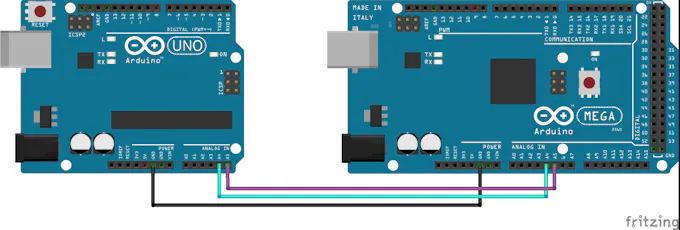
Follow steps to connect two Arduinos using software serial:
Assuming we use pins 8 and pin 9 for RX and TX on both Arduinos, connect pin8 on one Arduino with pin 9 on the other one, and pin 9 on the first Arduino to pin 8 on the second one.
- Connect the GND of both Arduinos together.
- If we don't power up both Arduinos via USB, then we need to power up at least one and connect 5V on each together.

Code
The master Arduino will receive commands from the computer and write them over the soft serial. Take a look at the Controlling the Arduino over serial project now.
// Include the Software Serial library
#include <SoftwareSerial.h> // Define a Software Serial object and the used pins
SoftwareSerial softSerial(8, 9);  // RX, TX
void setup()  {
    Serial.begin(9600);   softSerial.begin(9600);
}

void loop()  {
    // Check for received characters from the computer
    if (Serial.available())  {
    // Write what is received to the soft serial
    softSerial.write(Serial.read());   }
}
And here is the slave code that interprets the characters sent from the master. If the character is 'a', it will start the built-in LED. If the character is 'x', it will stop it:
// Include the Software Serial library
#include <SoftwareSerial.h> // Define a Software Serial object and the used pins
SoftwareSerial softSerial(8, 9);
// LED Pin
int LED = 13;
void setup()  {
    softSerial.begin(9600);
    pinMode(LED, OUTPUT);
}
void loop()  { // Check if there is anything in the soft Serial Buffer
    if (softSerial.available())  {
    // Read one value from the soft serial buffer and store it in the variable com
    int com = softSerial.read();
    // Act according to the value received
    if (com == 'x')  {
    // Stop the LED
    digitalWrite(LED, LOW);
    }     else if (com == 'a')  {
          // Start the LED
          digitalWrite(LED, HIGH);
            }
       }
    }
How it works…
Software serial simulates a standard serial port on different digital pins on the Arduino. It is very handy in general; however, it is simulated, so it doesn't have dedicated hardware. This means it will take resources, particularly execution time and memory. Otherwise, it works just like a normal serial connection. All the functions present in the normal serial port are also present in software serial.
Code Breakdown
First, we will look in the master code, which takes characters received on the normal serial port and writes them to our simulated serial connection. In the beginning, we include the SoftwareSerial.h library:
<strong>#include <SoftwareSerial.h></strong>
Then, we need to declare a serial object. We do so using the following syntax:
<strong>SoftwareSerial softSerial(8, 9); </strong>//RX,TX
The serial connection will be called, in this case, softSerial . It will use pin 8 for RX and pin 9 for TX. Take a look at the There's more… section for some information on which pins we can use.
Using the softSerial object, we can use all functions found in a normal serial connection, such as <a target="_blank" rel="noopener noreferrer" href="http://softSerial.read">softSerial.read</a>(), softSerial.write(), and so on. In this code, we check if there is anything in the real serial buffer. If there is, we read it from that buffer and we write it to the software serial:
<strong>if (Serial.available()) {</strong>
<strong>softSerial.write(<a target="_blank" rel="noopener noreferrer" href="http://Serial.read">Serial.read</a>());</strong>
<strong>}</strong>
In the slave code, we run a simplified version of the code from the Controlling the Arduino over serial recipe, except that we use a software serial. This only changes the declaration and instead of writing <a target="_blank" rel="noopener noreferrer" href="http://Serial.read">Serial.read</a>(), Serial.available(), and so on, we write <a target="_blank" rel="noopener noreferrer" href="http://softSerial.read">softSerial.read</a>() and softSerial.available() .
There's more…
Software serial has some important considerations and drawbacks. Here we tackle a few of them.
Usable Pins
We can't use every pin on the Arduino for software serial. For TX, generally, anything can be used, but for the RX pin, only interrupt-enabled pins can. On the Arduino Leonardo and Micro, only pins 8, 9, 10, 11, 14, 15, and 16 can be used, while on the Mega or Mega 2560 only 10, 11, 12, 13, 50, 51, 52, 53, 62, 63, 64, 65, 66, 67, 68, and 69 can be used.
More software serial connections
It is possible to have more than one software serial connection; however, only one can receive data at a time. This will generally cause data loss. There is an alternative software serial library written by Paul Stoffregen, which tackles exactly this problem.
Click here to open the related page.
Interference
The software serial library uses the same timer as a few other libraries. This means that other functions might be affected by the use of a simulated serial port. The best known interference is with the Servo library. The best way to overcome this is to use the Arduino Mega, or something similar, which has four hardware serial ports—enough for any project.
General connection tips
UART connections are very simple; however, there are three key aspects to remember. Whenever connecting two serial devices, the TX pin on one device goes to the RX pin on the other device. If we do that the opposite way, we might kill the device! Also, the devices need to at least share the same Ground (GND). Lastly, the devices have to be set at the same speed, typically referred to as the baud rate.
*******************************************************************************************************
I2C between Arduinos
Maybe sometimes we want to share the workload of one Arduino with another. Or maybe we want more digital or analog pins. Inter-Integrated Circuit or I2C (pronounced I squared C) is the best solution.
I2C is an interesting protocol. It's usually used to communicate between components on motherboards in cameras and in any embedded electronic system. Here, we will make an I2C bus using two Arduinos. We will program one master Arduino to command the other slave Arduino to blink its built-in LED once or twice depending on the received value.
Things you need
- 2 Arduinos - In this case, I am using DFRduino Uno Rev3 and DFRobot Mega2560
How to do it…
Follow these steps to connect two Arduinos using I2C:
- Connect pin A4 and pin A5 on one Arduino to the same pins on the other one.
- The GND line has to be common for both Arduinos. Connect it with a jumper.
Remember never to connect 5 V and 3.3 V Arduinos together. It won't hurt the 5V Arduino, but it will certainly annoy its 3.3 V.
Code
The following code is split in two parts: the master code and the slave code,which run on two different Arduinos.
First, let's take a look at the master code:
// Include the standard Wire library for I2C
#include <Wire.h>
int x = 0;
void setup() {
// Start the I2C Bus as Master
Wire.begin();
}
void loop() {
Wire.beginTransmission(9); // transmit to device #9
Wire.write(x); // sends x
Wire.endTransmission(); // stop transmitting
x++; // Increment x
if (x > 5)
    x = 0; // reset x once it gets 6
delay(500);
}
And here is the slave code that interprets the characters sent from the master:
#include <Wire.h>
int LED = 13;
int x = 0;
void setup() {
    pinMode (LED, OUTPUT);
    // Start the I2C Bus as Slave on address 9
    Wire.begin(9); // Attach a function to trigger when something is received.
    Wire.onReceive(receiveEvent);
    }
void receiveEvent(int bytes) {
    x = Wire.read();
    // read one character from the I2C
    }
void loop() {
    //If value received is 0 blink LED for 200 ms
    if (x == '0') {
        digitalWrite(LED, HIGH);
        delay(200);
        digitalWrite(LED, LOW);
        delay(200);
        }
    //If value received is 3 blink LED for 400 ms
    if (x == '3') {
        digitalWrite(LED, HIGH);
        delay(400);
        digitalWrite(LED, LOW);
        delay(400);
        }
    }
How it works…
To briefly go through the theory, I2C requires two digital lines: Serial Data Line (SDA) to transfer data and Serial Clock Line (SCL) to keep the clock. Each I2C connection can have one master and multiple slaves. A master can write to slaves and request the slaves to give data, but no slave can directly write to the master or to another slave. Every slave has a unique address on the bus, and the master needs to know the addresses of each slave it wants to access. Now let's go through the code.
Code breakdown
First, let's look at the master. We need to include the required Wire.h library:
<strong>#include <Wire.h></strong>
Then, in the setup function, we begin the I2C bus using the Wire.begin()function.
If no argument is provided in the function, Arduino will start as a master.
Lastly, we send a character x, which is between 0 and 5. We use the following functions to begin a transmission to the device with the address 9, write the character, and then stop the transmission:
<strong>Wire.beginTransmission(9);</strong> // transmit to device #9
<strong>Wire.write(x);</strong> // sends x
<strong>Wire.endTransmission();</strong> // stop transmitting
Now let's explore the slave Arduino code. We also include the Wire.h library here, but now we start the I2C bus using Wire.begin(9). The number in the argument is the address we want to use for the Arduino. All devices with address 9 will receive the transmission. Now we need to react somehow when we receive an I2C transmission. The following function appends a trigger function whenever a character is received. Better said, whenever the
Arduino receives a character on I2C, it will run the function we tell it to run:
<strong>Wire.onReceive(receiveEvent);</strong>
And this is the function. Here, we simply store the value of the received character:
<strong>void receiveEvent(int bytes) {</strong>
<strong>x = <a target="_blank" rel="noopener noreferrer" href="http://Wire.read">Wire.read</a>();</strong>
<strong>}</strong>
In loop(), we simply interpret that character to blink the built-in LED at different speeds depending on the received character.
There's more…
I2C is a complicated transmission protocol, but it's very useful. All Arduinos implement it, with a few differences in pin mappings.
Comparing different Arduino categories
The pins for I2C are different in different Arduino categories. Here are the most common:

More about I2C
Each I2C bus can support up to 112 devices. All devices need to share GND. The speed is around 100 kb/s—not very fast but still respectable and quite useable. It is possible to have more than one master on a bus, but it's really complicated and generally avoided.
A lot of sensors use I2C to communicate, typically Inertial Measurement Units, barometers, temperature sensors, and some Sonars. Remember that I2C is not designed for long cable lengths. Depending on the cable type used, 2 m might already cause problems.
Connecting more devices
If we need to connect more than two devices on an I2C bus, we just have to connect all SDA and SCL lines together. We will need the address of every slave to be addressed from the master Arduino.
You can find a good explanation on how a master should request information to a slave here. This is an example closer to real life, as this is the way we usually request information from sensors.