tEEonE
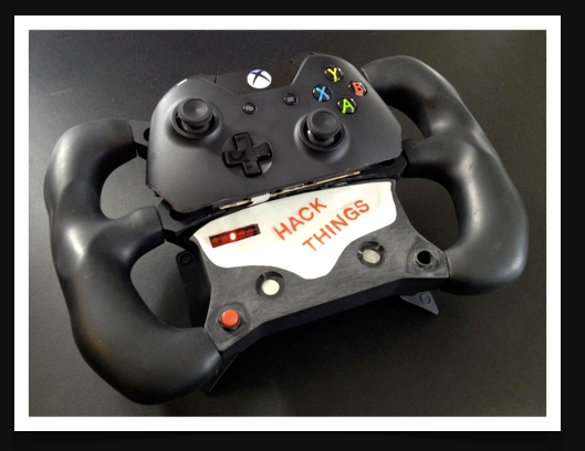
Introduction
- I love racing games, and along with the Xbox One came Forza 5!
- The few steering wheels for XB1 are super expensive and bulky
- The XB1 controller is a new device and i was dying to take one apart
- I had a spare SRW-S1 lying around
- I thought it would be a cool hack!
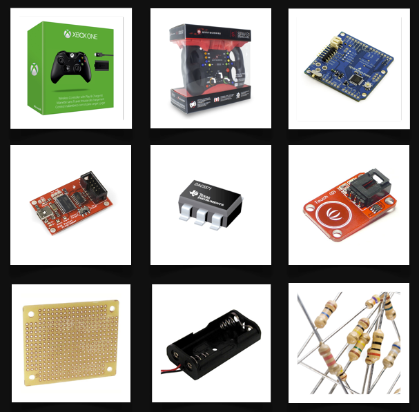
Parts used
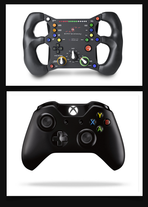
- Xbox One Controller
- Simraceway SRW-S1
- Arduino Pro & AVR programmer
- TI DAC551 & adapter board
- 2 x TTP223 based touch sensor module
- Perfboard & pin headers
- Battery holder 2 x AA
- Misc. resistors
Err.. why?
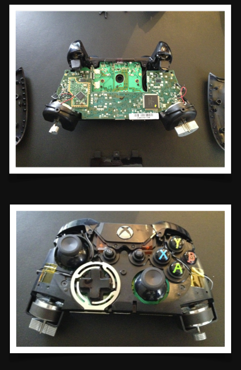
I started by purchasing a XB1 controller and proceeded to take it apart (don’t you just love buying stuff and take it apart even before its initial use). The XB1 controller has a nice mechanical build, which means that you end up with pretty much all the electronic parts still attached together and working while having no external housing components attached. This made it easier to figure out how it works, and do the needed measurements. I was only interested in replacing the inputs for steering, gas and brakes. I then proceeded to take apart the SRW-S1, just to find out that this was very suited for the hack as well. The main body has lots of space once the PCBA is removed, so I would be able to fit in whatever I needed. The paddles were mechanically functional without the original PCBA, and the accelerometer was actually mounted in a module, that could easily be detached, and as you’ll later find, even the PCB layout for the rest of the wheel, accommodated for some easy hacking
Mechanical
The SRW-S1 provided a great platform for this build! After the PCBA was removed, there was very little mechanical alteration needed. There was some basic things like screw bosses that could get in the way, but they were easily removed with a Dremel. Also a couple of holes were cut in the original housing to accommodate the rumble motors, and two 3D printed parts were added, to seal off the holes. The front housing of the SRW-S1 was cut in half down the middle - following a horizontal line. This provided a two piece top cover, that could be taken off independently.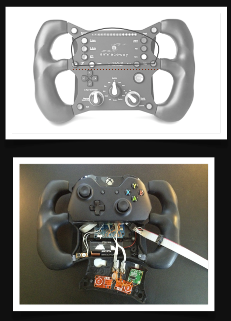
Electronics overall
The project relies on a few basic hacks; feeding the controller the right voltage levels at the right points. Ill get into the details of steering and gas/brake later, but in general I knew the hack needed a micro controller. I opted for an Arduino - this is my go to platform for rapid prototypes in many cases; development is fairly straightforward, the platform is pretty forgiving if you mess something up, but most importantly; there is a huge open community.
Because this project is powered off the XB1 controllers battery, it was important that the micro controller worked on 3.3 V. This is an easily sourced voltage on the controller. I had an Arduino Pro (basically a Duemilanove with ATmega328, but rigged to run on 3.3V instead of 5V) around, that i thought would be great for reading the accelerometer and controlling the outputs.
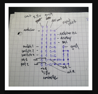
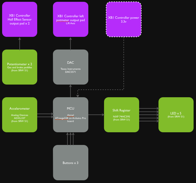
Block diagram![]()
Power
I wanted to make the steering wheel wireless. This is something that i have wanted since i first tried the SRW-S1. The design of the wheel (no base, no pedals) basically screams out COUCH CONTROLLER. This meant that i had to drive everything, off the XB1 controller’s battery. As most digital electronics start acting wonky when the power gets too low, i searched the controller PCBA for a regulated 3.3 V source. I found one, but actually ended up using another, due to power constraints on the first one. The batteries got put in a battery case, and connected to the battery terminals on the XB1 controller. I did a simple perfboard that served as power terminals, as well as basic connections and some resistor wiring. During firmware development/uploads i turned the controller, and thereby the Arduino off, and powered it thru the Sparkfun AVR programmer. The Arduino Pro has a switch that switch between “batt” and “ext” but i found that having it in “batt” position worked for both battery and AVR programmer operation.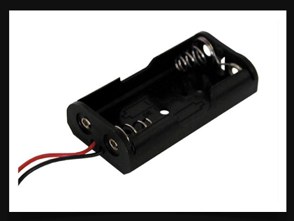
Steering
On the XB1 controller, steering is normally handled by a single potentiometer built into the left joystick. I figured that I just had to disconnect the original potentiometer and then feed the right voltage level to the to the output pad of the original potentiometer. Instead of removing the original potentiometer, I decided to just cut the power trace, so it was no longer connected. Before cutting, I measured the output voltages of the potentiometer - left was 0 V, center was 0.9 V and right was 1.7 V.
The plan was to have the steering controls handled by the original accelerometer from the SRW-S1. The accelerometer is the Analog Devices ADXL337. A simple device with three axis analog outputs. I only needed X and Y so I connected those to a pair of analog ports on the Arduino.
Reading the values using the build in ADC on the Arduino is very straightforward. I apply a bit of algorithms to handle the main calculation of the rotation angle, and also in order to calibrate sensitivity as well as overall sensor mounting angle.
I had a DAC lying around, and decided that this would fit the purpose just fine. It has an I2C interface, and basically I just map the rotation angle to a voltage level on the DAC - between 0 V and 1.7 V. The DAC I had, is an SMD type component, so I used a little SMD adapter/mounting board in order to wire it. The DAC was then connected to the output of the original turn (left) potentiometer of the XB1 controller,, and basically the XB1 controller has no idea that its a DAC feeding it instead of the original potentiometer.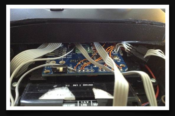 The green board on top of the Arduino Pro is the accelerometer.
Gas & Brakes
Gas and brakes is controlled by the right and left trigger respectively. on the XB1 controller. These are build using Hall Effect sensors and a pair of magnets which are mounted on the triggers. This gives for a very simple mechanical design, and a very high degree of durability. Hall effect sensors basically just measure the magnetic flux level and outputs a voltage level based on that. I measured the sensors to have an output voltage of 0.4 V to 0.8 V. depending on the trigger position; from fully pressed, to fully released. The hall effect sensors were removed, and it was time to start looking at the paddles on the SRW-S1.
The gas and brake paddles on the SRW-S1 are based on two simple potentiometers, and a couple of springs. The potentiometers are 10K Ohm, so for me to end up with 0.4 V to 0.8 V from a 3.3 V supply, there was a bit of resistor calculation to get done. Basically I built a two step voltage divider where the first divider gives me 1.8V, and the the next step that includes the potentiometer outputs 0,4 - 0.8 V depending on the position of the paddle.
The output of the left and right paddle then got wired to the original output pads of the (now removed) hall effect sensor. Again, the XB1 controller does not know that it is being fed through a plain resistor network instead of the original hall effect sensor.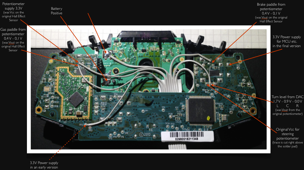
Click picture to open in new window/tab to read those itty bitty letters!
Other UI elements
I knew that i wanted to be able to control things like sensitivity and general angle calibration, so I decided to add a three button control system; one button for toggling thru a list of menu items, and two buttons used to increase and decrease levels of a given option. For the menu toggle button I chose to re-use one of the existing buttons from the SRW-S1, and for the two level up/down buttons I chose a pair of touch sensitive button modules. Touch sensitive buttons are nice for hacks, as you don’t need to fit switches anywhere, and basically they work thru most plastics below 2 mm thickness.
In order to see which options I was changing, I needed a feedback system. Originally i wanted to add an I2C OLED, but felt that it was a little overboard for a simple device like this. Then my mind came across the nice LED strip that it already found on the SRW-S1. There are 15 LEDs used as a tachometer indication, driven by a pair of 595 shift registers.
I figured that the easiest way would be to simply re-use the existing PCBA from the SRW-S1, and luckily the traces were laid out in a way that made it possible to simply cut a piece out and re-use directly! The 595 was connected to a couple of IOs on the Arduino. I decided for a configuration with 5 LEDs. When the menu button is pressed, it cycles thru three different modes;
Normal functionality - just shows the current angle by a single LED; so when the wheel is tilted to the left, the left most LED lights up, little bit further to the right and the next one lights up - all the way to the right, and the rightmost one lights up - you get the point.
Sensitivity - indicated by two LEDs that can either be close to the middle or further out to the sides, depending on high or low angular sensitivity.
Basic calibration - for basic flaws in the sensor positioning (havent needed to calibrate actually).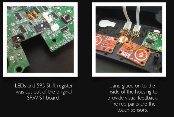
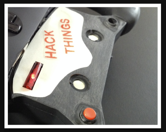 LED array in the left hand side of the picture. The red button is the menu toggle button, and the two metallic circles are the touch buttons for level adjustments.
Rumble
The XB1 controller has extended the rumble features from just regular rumble using two fairly large motors with counter weights in each handle, to also include a pair of smaller counterweight motors in each trigger. This provides a really nice feedback in games, with almost “force feedback” type properties.
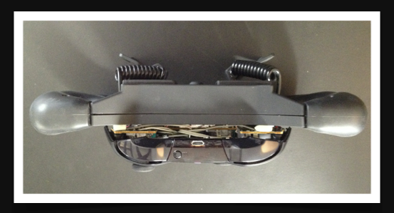
I of course wanted to take advantage of both, and luckily i was able to fit the big rumble motors inside the main housing - only a couple of tiny holes were needed, and the motors were glued on to the backside of the top cover.
For the smaller trigger motors, I printed a couple of attachment parts on a basic 3D printer and got them glued on to the gas and brake paddle. These really provide a great feedback and makes the experience a lot more immersed! As the paddles move physically when pressed, I connected the trigger rumble motors to the XB1 controller PCBA using a couple of cool coiled cords, from an old USB power bank.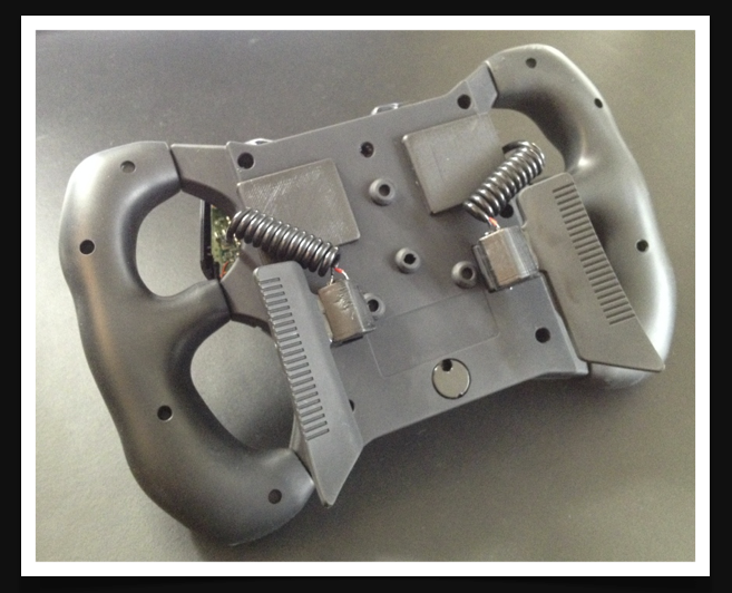
Firmware
The firmware functionality is pretty straightforward;
1. Read values from the accelerometer, and convert to an angle
2. Check whether the mode button is pressed, and if so change mode
3. Check whether value buttons are pressed, and change values of the selected mode (sensitivity or calibration)
4. Set the LED status accordingly
5. Apply calibration and sensitivity data
6. Send rotation value to DAC
7. Start over
The firmware was written in the regular Arduino IDE, and some portions like the calculation of the angle from the accelerometer values, was just found online. The code is available on Github;
github.com/tinosoelberg/SteeringWheelOne
All done!
Steering Wheel One - Demo from Tino Soelberg on Vimeo.