 zakqwy
Took a personal day off work to finish demo work on my second floor (ah, projects...), then it started raining around 10am. What to do, what to do...
We're now on v06. I switched theta servos several times, so if anyone is looking for solid models of 'em: check the Dropbox repo. Accuracy not guaranteed, since they're based on manufacturer's prints (and they don't like to publish shaft locations for some silly reason).
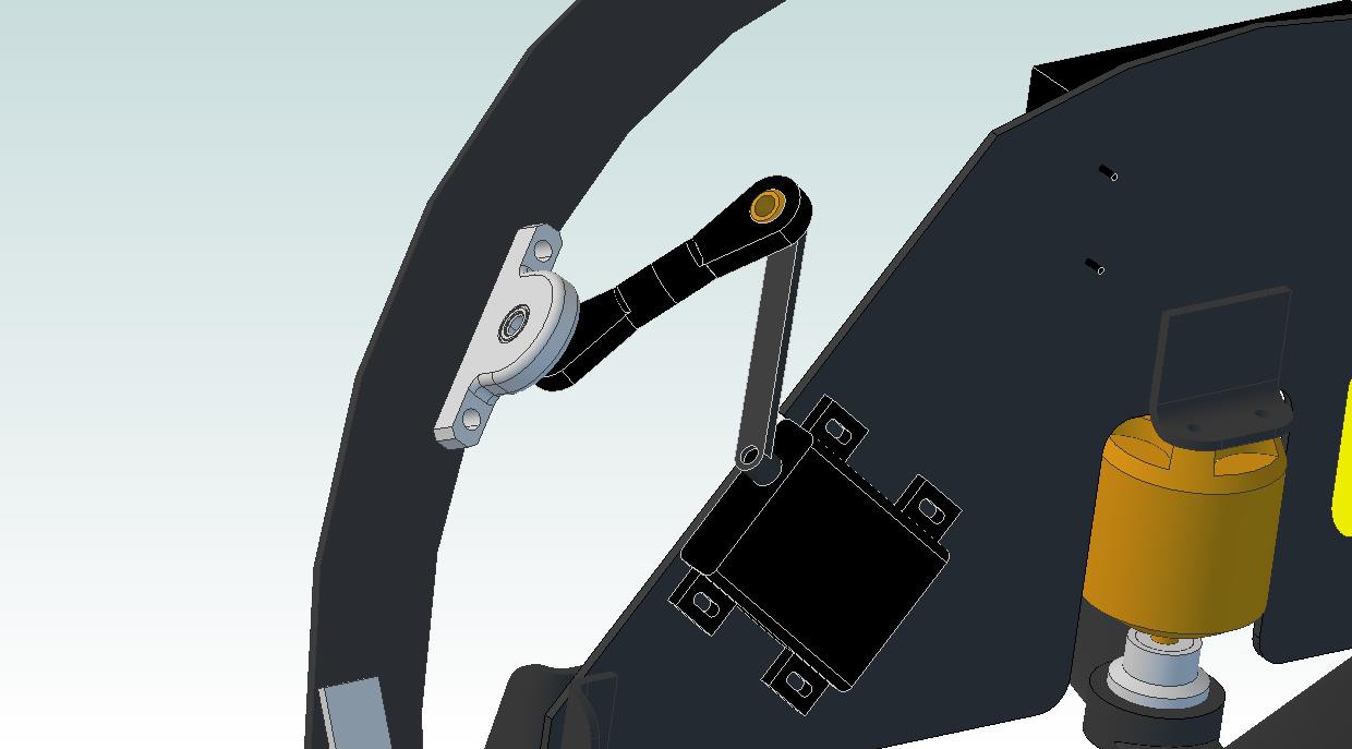
A few notes on the image above:
- That's a Hitec HS-7115TH servo originally designed for installation in RC wings. Titanium gearset, double ball bearings, programmable, etc... seems to be a pretty legit unit, although it's not particularly cheap. 50 oz-in with 0.10s 60 degree actuation (at 7.4vdc) better be enough, because it's about the best I can find in this form factor.
- I originally recess-mounted the servo with a matching cutout on the CFRP plate; that would have made the drive axis in line with the center of the plate (well, it would be off by 0.8mm, but close). Switched it up to a spacer design for a few reasons:
- Spacers (not shown) will give us some leeway on alignment. I'll also slot the CFRP holes perpendicular to the slots on the servo itself so I can tweak servo angle if necessary.
- Even though the plate is really strong, I was a bit concerned about taking a huge chunk out. I think doing some basic calculations would help this, but.. it hasn't happened. Oh well.
- I found tiny nice looking pillow blocks that seem like an easy solution for the pitch ring mounting point, and they've inherently got a 3/8" offset (plus 0.8mm). I'd like to come as close to matching that as possible to avoid too many alignment issues.
- Speaking of alignment: if you pull apart the solid models of the pitch ring and motor plate (specifically, the extrude cuts and associated sketches that define the servo and pillow block mounting points), you'll notice that I based their angle off of a radial reference line that starts at the center of the plate or ring. Seems like I want the rotational axis of the servo to be in line and parallel to this line, so.. it is.
- I'm impressed that the program was able to model the linkage rod ends so well. They're actually little assemblies: the brass balls are separate from the nylon housings, and they're connected using a single constraint in the assembly. Makes it really fun to move the plate back and forth to check range of motion and interferences.
Overall thoughts: this linkage setup will require a custom-length servo horn, but all of the other parts are off-the-shelf. The servo can be programmed to allow 180 degree rotation, and using that whole range will give us a theta rangeability of +/- 30 degrees: should be waaay more than I need for basic stability control.
Discussions
Become a Hackaday.io Member
Create an account to leave a comment. Already have an account? Log In.
The crucial difference is the axis of the servo and pillow block should point in towards the center of the sphere they pivot around. The spherical bearing will take up the difference and remain at a constant offset.
See:
https://www.google.com/search?q=Spherical+four-bar+mechanism&es_sm=93&source=lnms&tbm=isch&sa=X&ei=IHp7U-HVBMOeyATks4LoCg&ved=0CAgQ_AUoAQ&biw=1920&bih=1096
Are you sure? yes | no
I'll double-check the sketches for the pillow block and servo mounting extrude cuts, but I'm pretty sure I used reference lines that intersect the center of the sphere to locate their rotational centers. Can you see those on the CAD models when you dig in to the sketches?
[pay no attention to the 'underdefined' warnings.. someday I'll learn how to properly dimension stuff]
Are you sure? yes | no
Are you sure? yes | no
Definitely looking for suggestions here. Us matsci folks never had to take kinematics, so my understanding of linkages is almost entirely based upon childhood experiences with LEGO Technics.
Are you sure? yes | no