 zakqwy
I got the outer servo mounted and its linkage sorted; I also soldered up a temporary wiring harness so I could easily power both axes. First, a quick video:
As I mentioned in the video, I got lazy--no ramping on the servos. I also didn't see Curtis' excellent comment until after these tests; I'll be adding a cap to the servo supply leads to avoid sag on the power rail. Great call. Now, a few pictures:
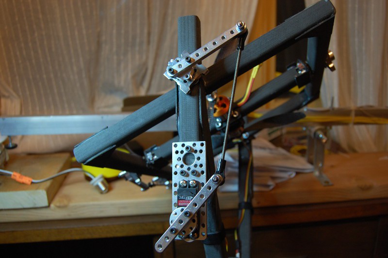
Outer servo mount and linkage, shown with GimbalBot upside-down. Note that the servo gets a bit of a mechanical advantage since its linkage arm is short; I actually tested the servo with equal length arms to no ill effect, but I decided to pull it in a bit for further tests:
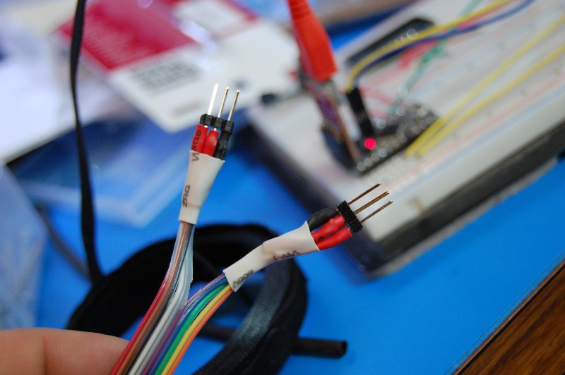
I used a few bits of header to build a temporary wiring harness so I could test both servos simultaneously without yanking the wires out of my breadboard. The ribbon cable I had on hand is a bit thin, so I doubled up the power and ground leads:
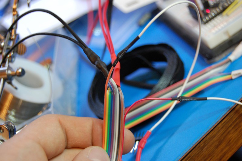
Did I ever mention how much I love heat shrink tubing? On a more serious note, I'm glad I did a continuity check on the harness; I'd accidentally swapped a few connections between here and the servo connections, so I did the following portion twice (the second time after a dinner break):
No surprise here: GimbalBot needs to go on a diet. I figured I would be a few hundred grams overweight, especially including the spool of heavy-gauge wire I'm planning to use to power the brushless motors (the wire alone weighs 150g). I also didn't account for nuts and bolts in my drawing. Or space glue. Oops:
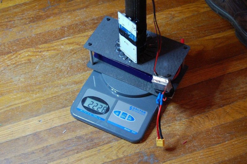
I'm not bummed about the weight. I've got a few pairs of 10" props on the way; the prop thrust calculator I've previously learned to trust suggests I'll need to spin them at 9500 RPM to hit the thrust shown on the scale above, and doing so will draw less than 500 watts for both motors including efficiency losses. With my current ESCs and motors, I should be able to top out at 3.5kg of thrust for short periods of time.
3.5kg of thrust. That is a lot.
GimbalBot is kind of scary.
- Zach
Discussions
Become a Hackaday.io Member
Create an account to leave a comment. Already have an account? Log In.
It would be great to see a video of a slow (<<1 hz) sine input to the 2 dof mechanism to see it run through it's ROM.
Also of note: soon you'll want to work out the transmission ratios for your servo linkages. Given the large sweep angle, it will be decidedly nonlinear. You can work out the relationship here: http://iel.ucdavis.edu/chhtml/toolkit/mechanism/fourbar/transangle.html
-Geoff
Are you sure? yes | no
Good call on the sine input, too. Random 20 Hz/30 degree twitches aren't terribly practical (or kind to the servos, for that matter). I'll plan to do that when I start thrust testing. Maybe I'll make the signals 90 degrees out of phase so I get a nice circle.
Speaking of which--no update yet (for once!), but I made some progress last night. The wiring harness to power the brushless motors is finished, and I made a few modifications to the thrust testing rig to hold GimbalBot at roughly the right point. I'm busy tonight and out of town this weekend, but I might be able to get a few tests done Friday.
Are you sure? yes | no