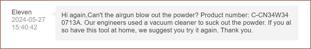
So I asked Eleven what the engineers did the last time:
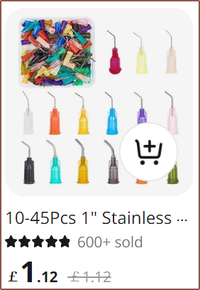
So I was wondering how I could line that up, since a standard vacuum didn't sound like the best idea, and then I saw syringe nozzles as a recommendation in AliExpress:
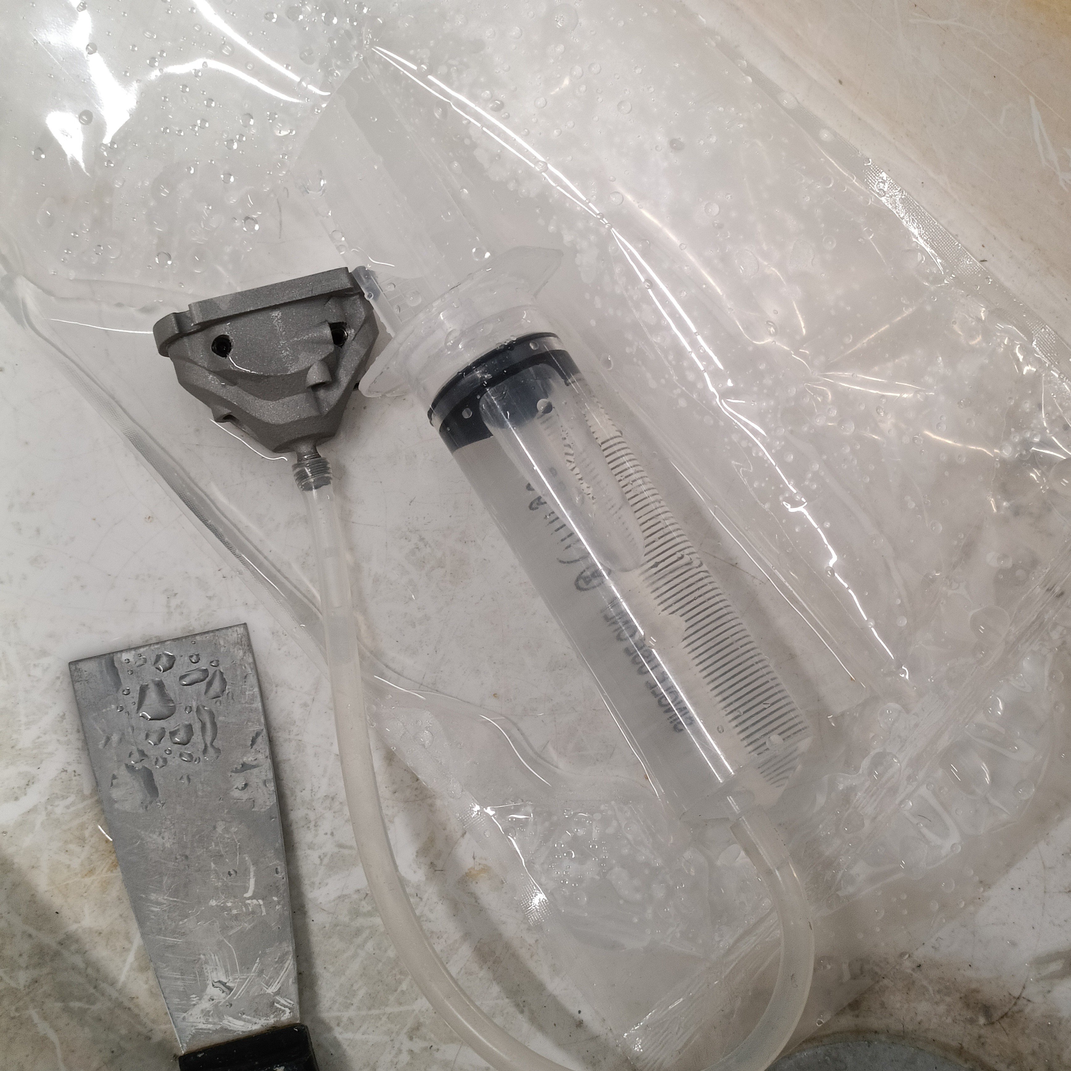
So I went and used the syringe and tube my uni just happens to have:
As you can see, the syringe is full of water. This is because I wasn't able to generate sufficient pressure by pumping air into the c8or and the atmosphere generated even less when suction was used.
The only win I was able to get was to unblock ch8. All other channels stayed blocked, but water did drip through them.
Day 2
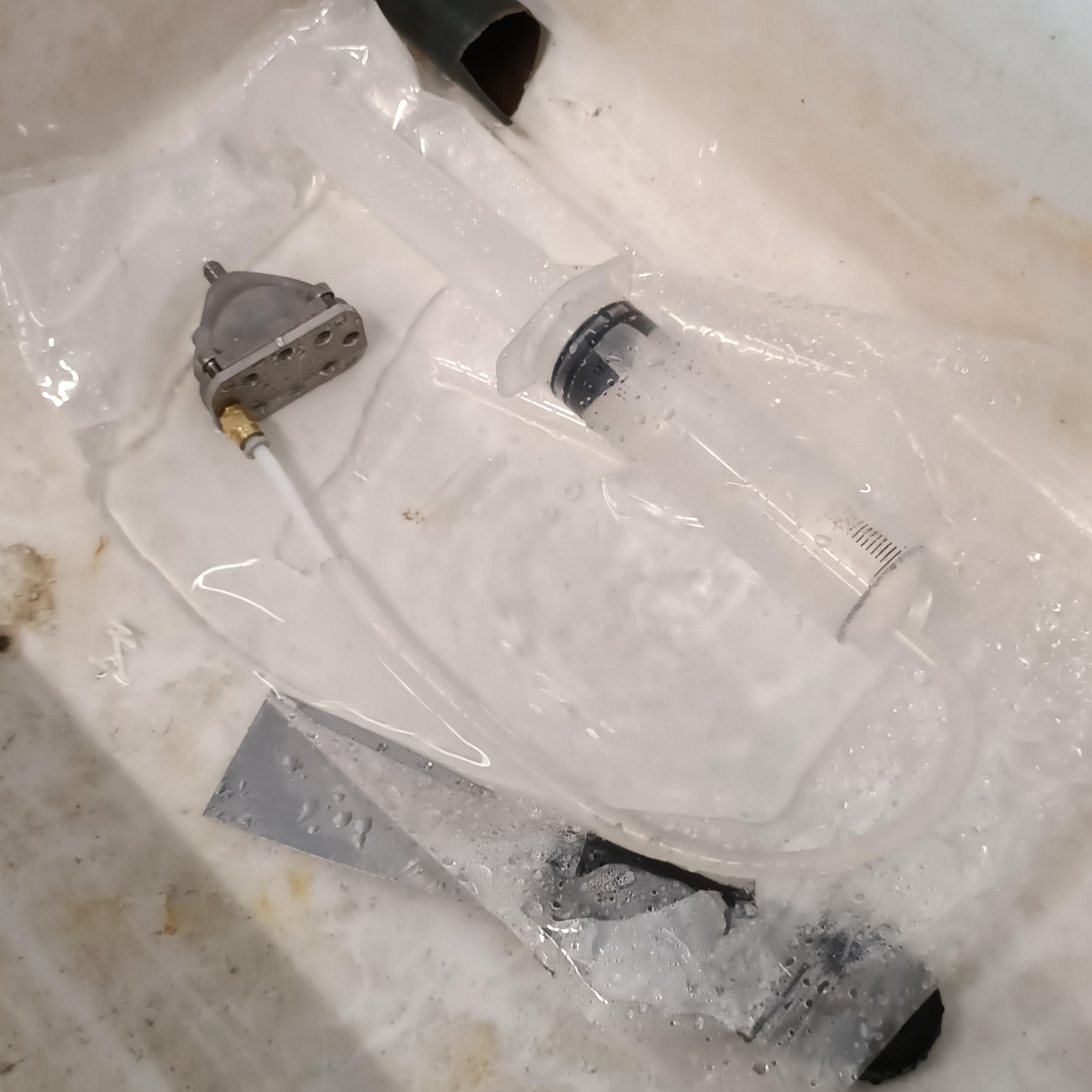
The idea was to come in from the other side.
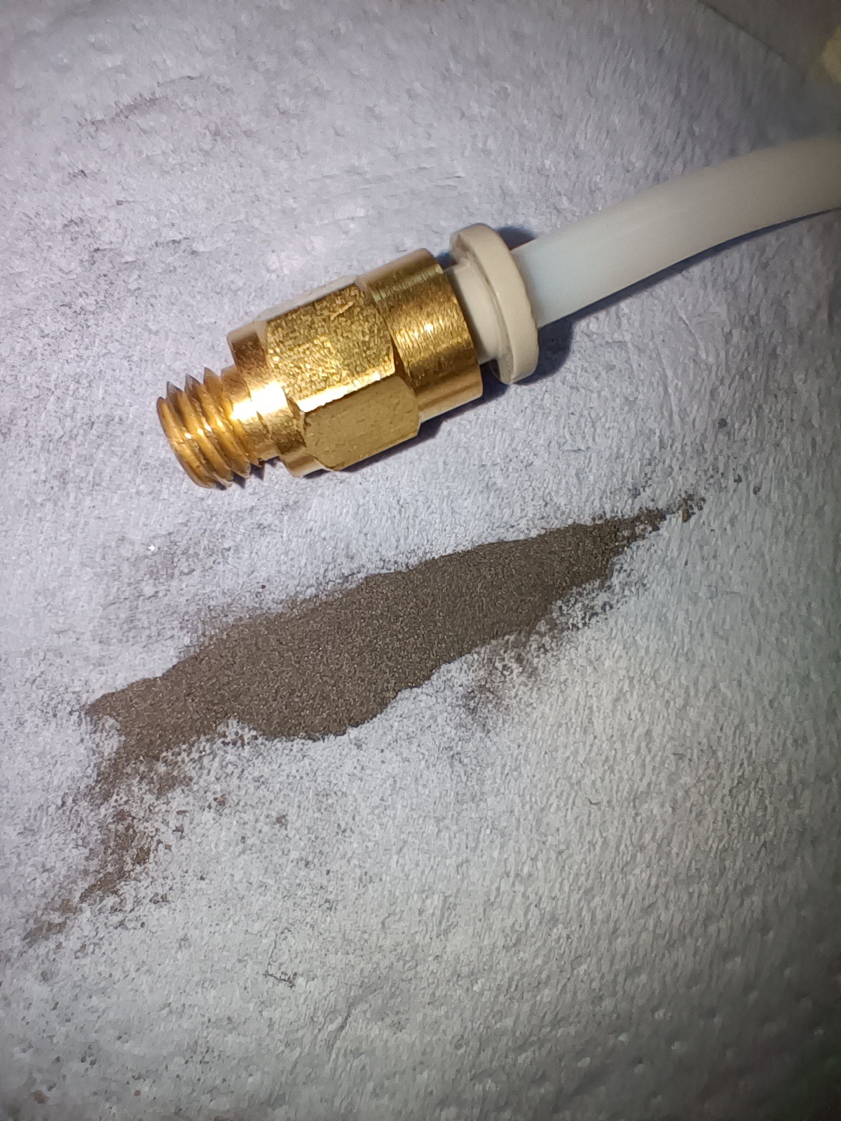
The uni also happened to have some bowden tube and a coupler.
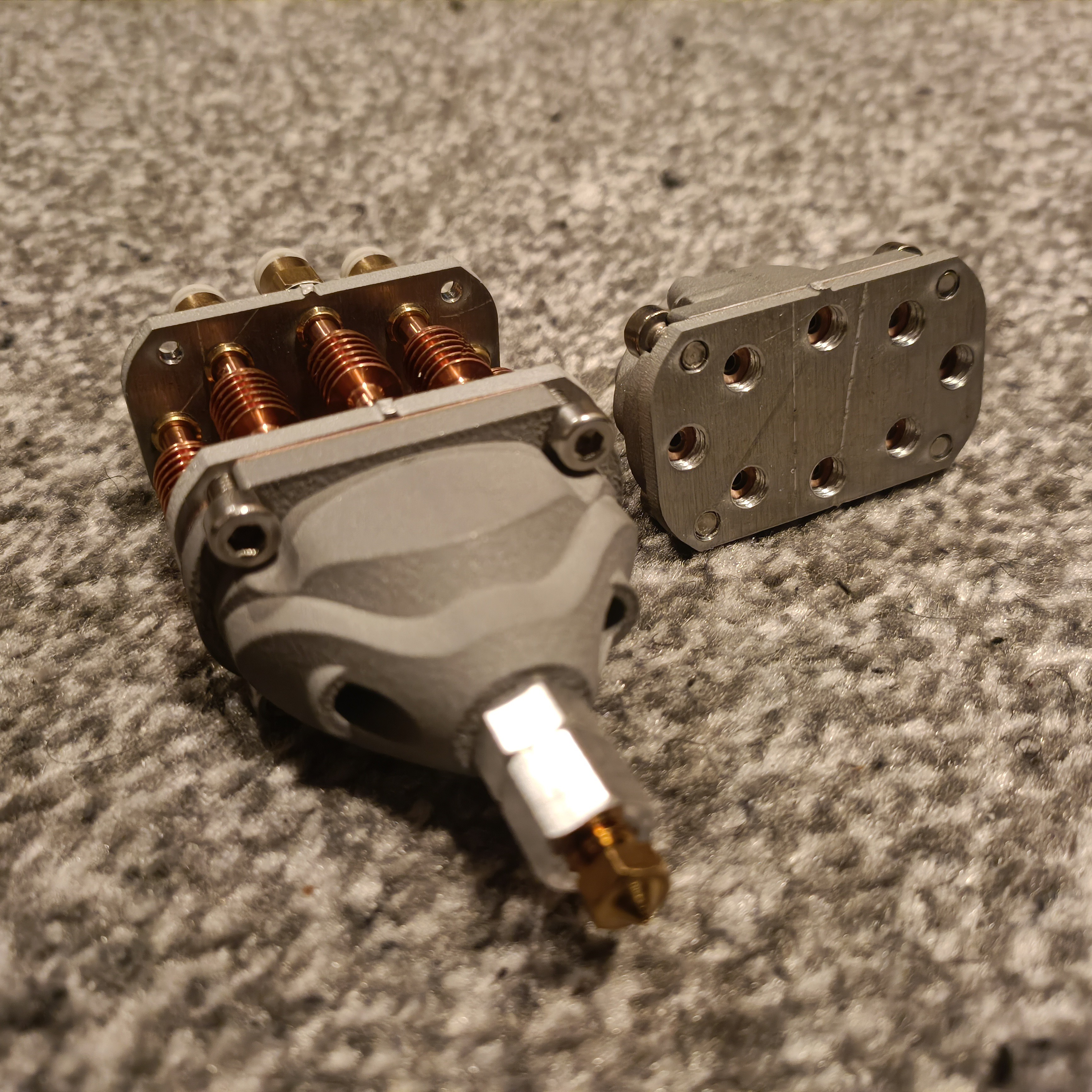
All I learned was that the copper gasket 100% works without any uncertainty or doubt. I was able to apply maximum water pressures on all channels and the plunger didn't budge. It also means that I took the correct call and not just tried to extrude the powder out with plastic, because it wouldn't've displaced out the powder either.
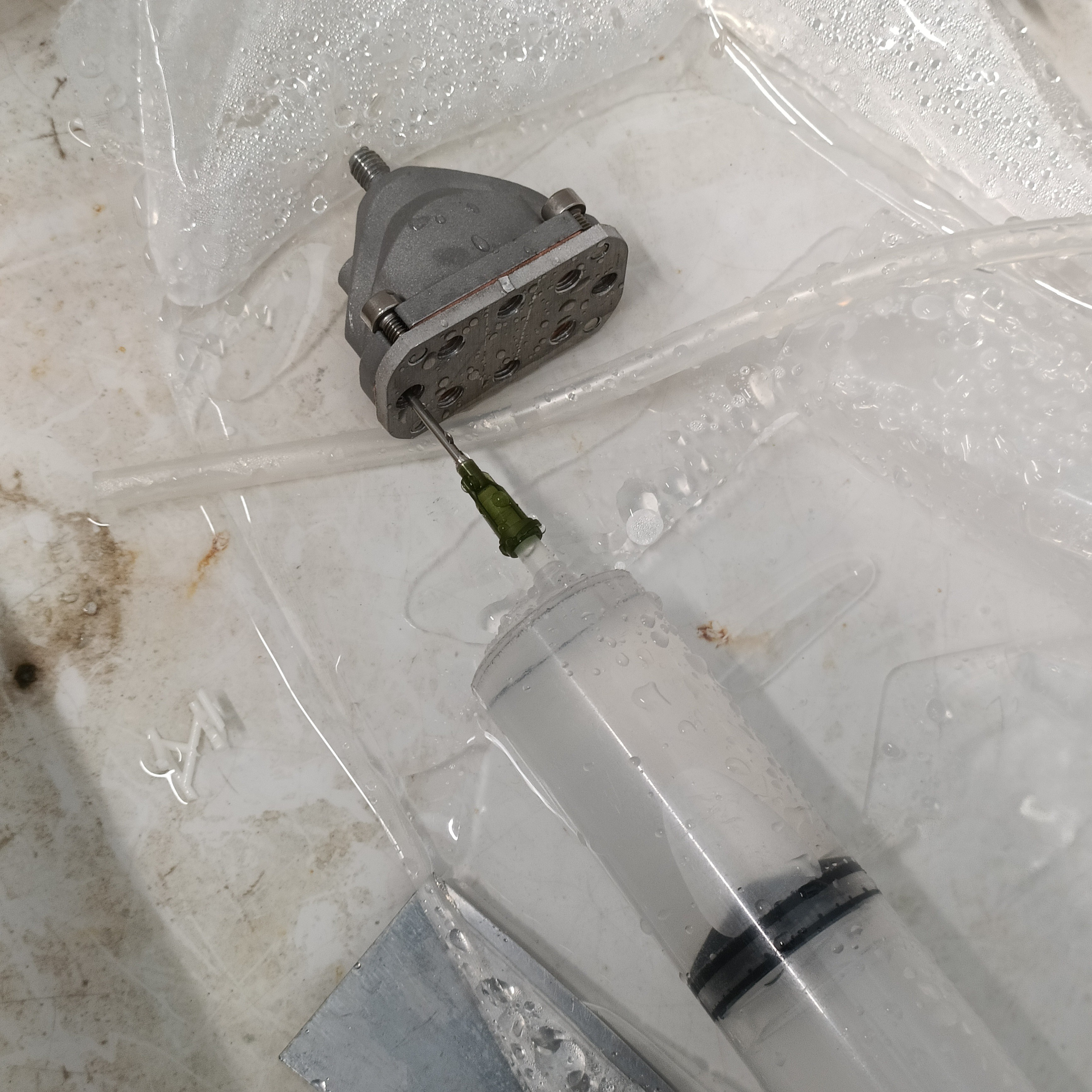
I tried the needles that also happened to exist, wondering if the powder just needed an escape route, but still no success.
The Coaxial8or and copper gasket are kind-of stained now, after all that water.
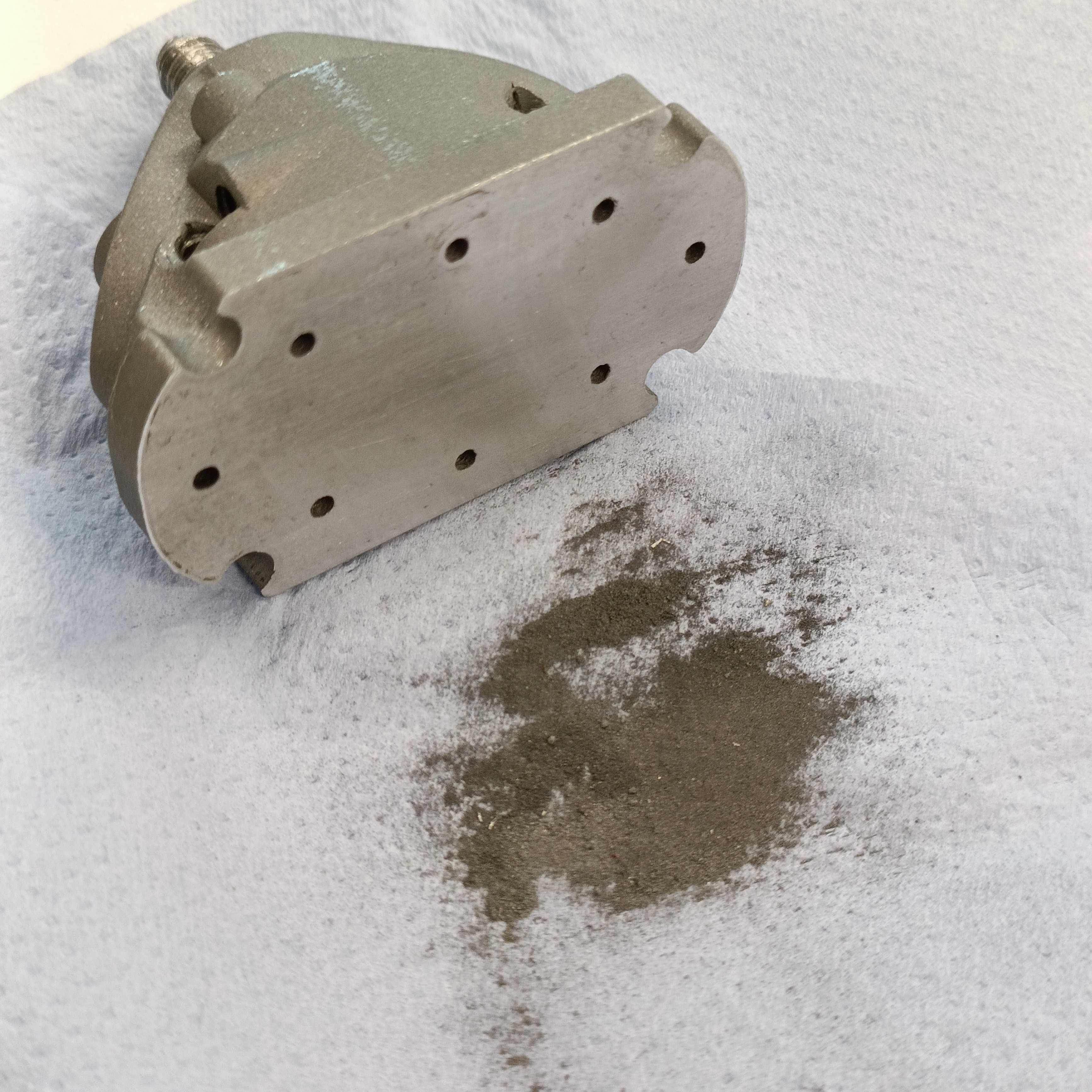
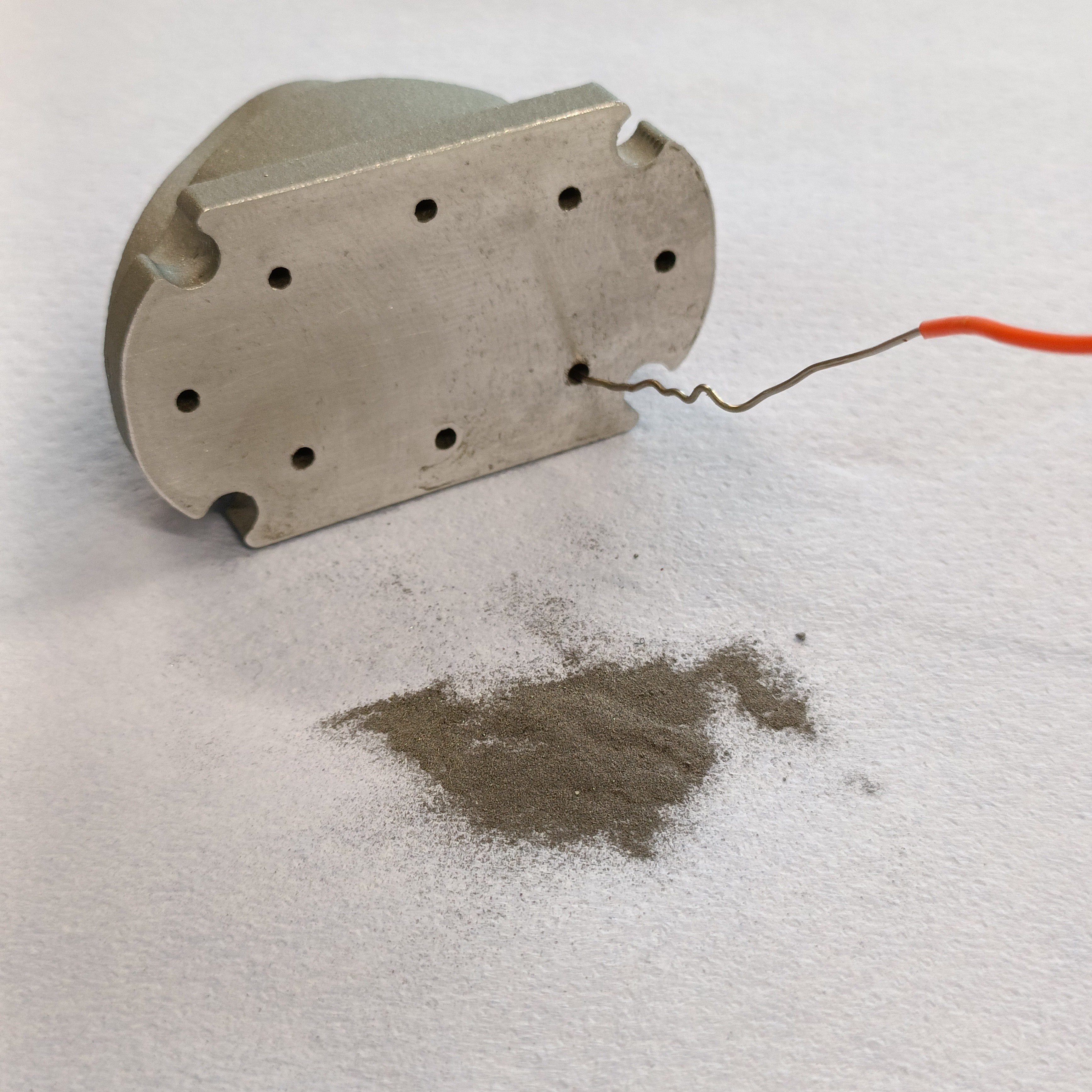
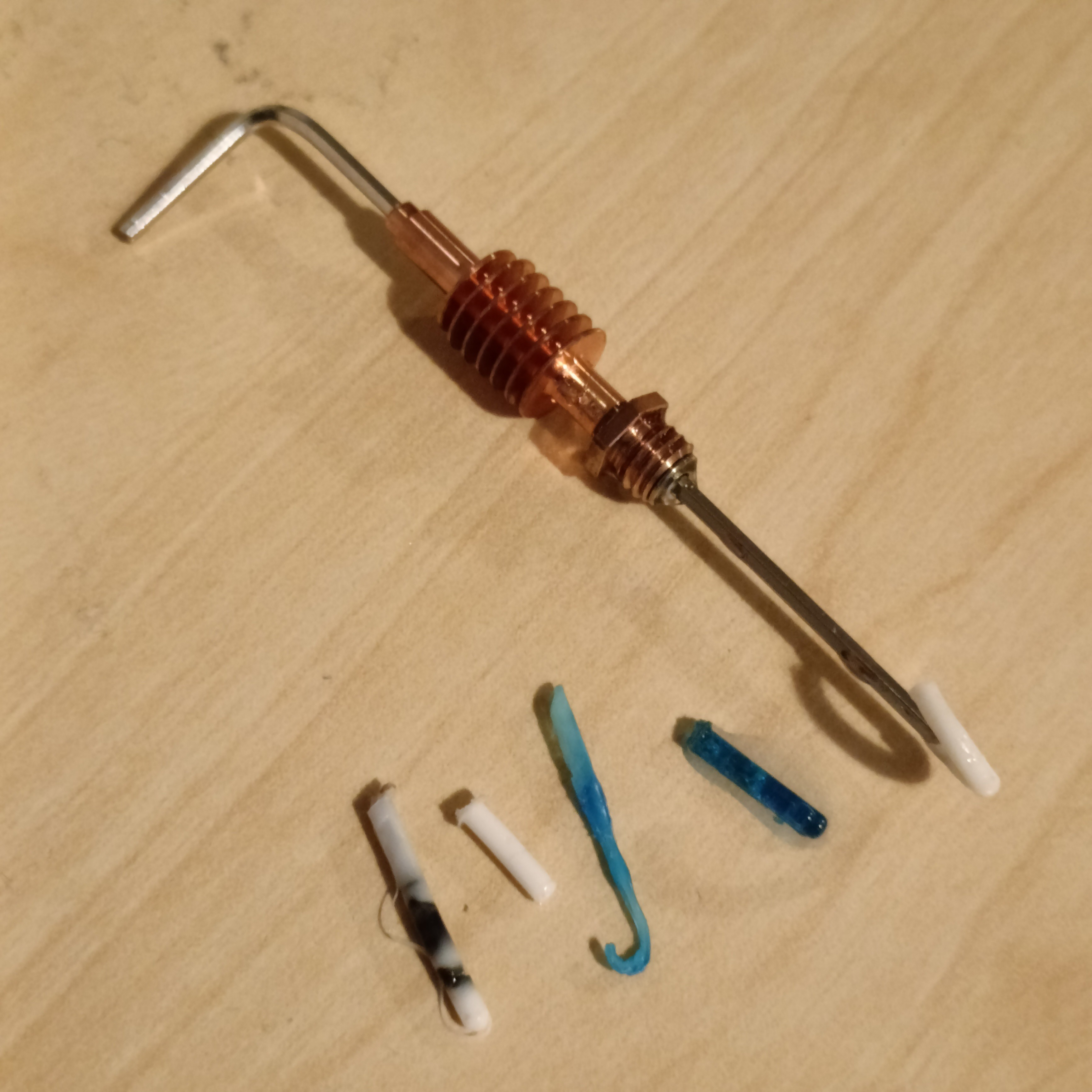
Looking through the macro lens of my phone, I could see that the other, dry c8or still had visible powder so I tried the classical resistor-wire pickaxe-floss method and all this dust came out:
Thus, I was wondering if the dust needed to be agitated. "Hm, what I need is maybe like an ultrasonic cleaner or something. Are any of these machines [around me] one?", I thought.The uni indeed happens to have a "professional ultrasonic cleaner" behind/under some empty bottles.
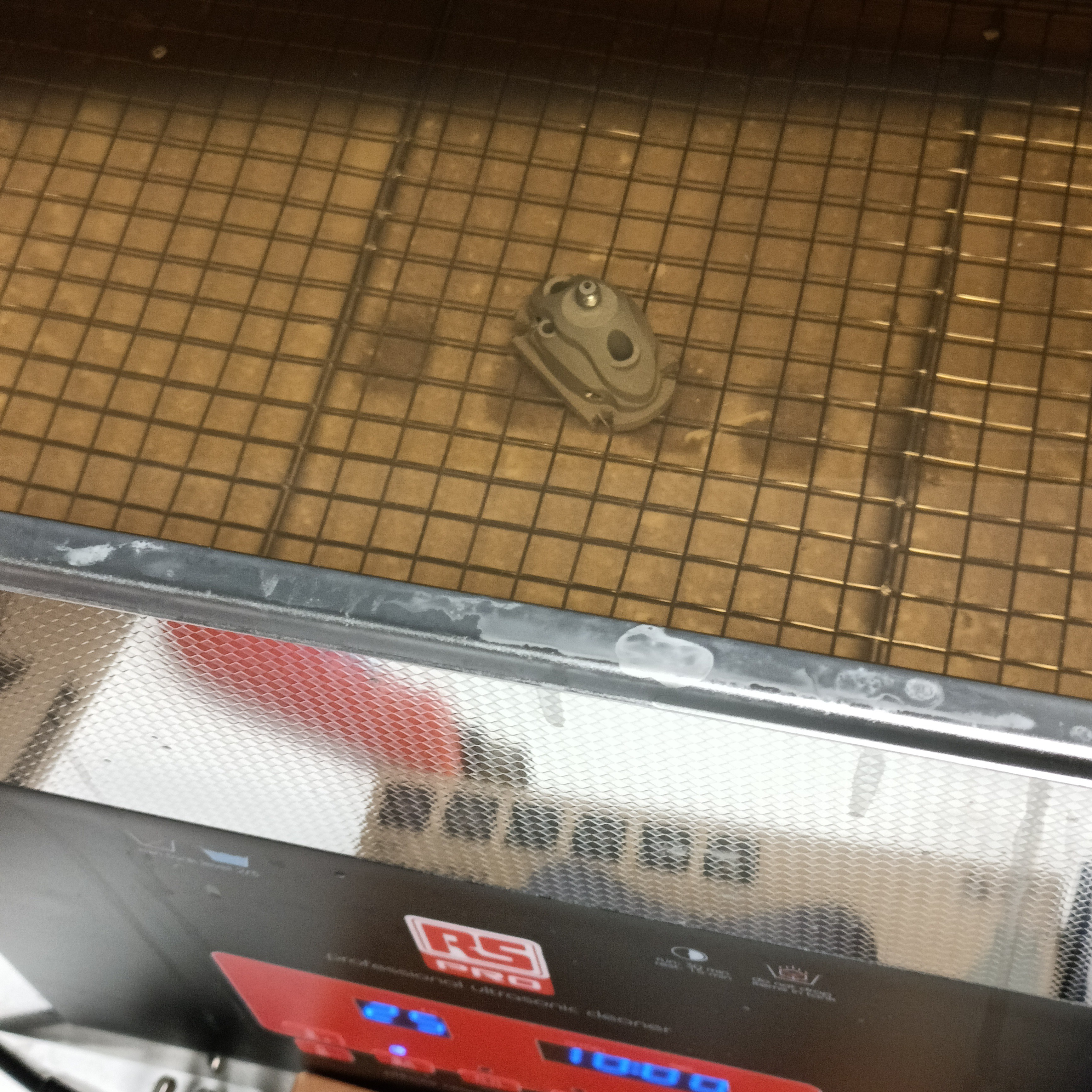
As instructed by the control panel, I looked up and read through the instructions and then put the wet c8or in. My strategy here is that I keep one of the c8ors dry, because it's possible that the water surface tension could "dough-ify" the powder.
No idea why the liquid is orange.
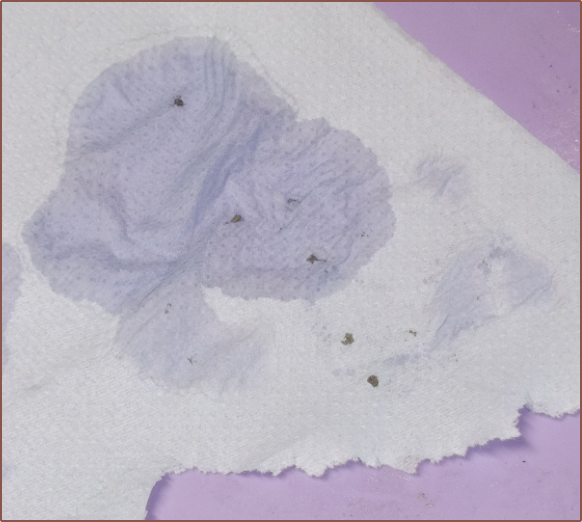
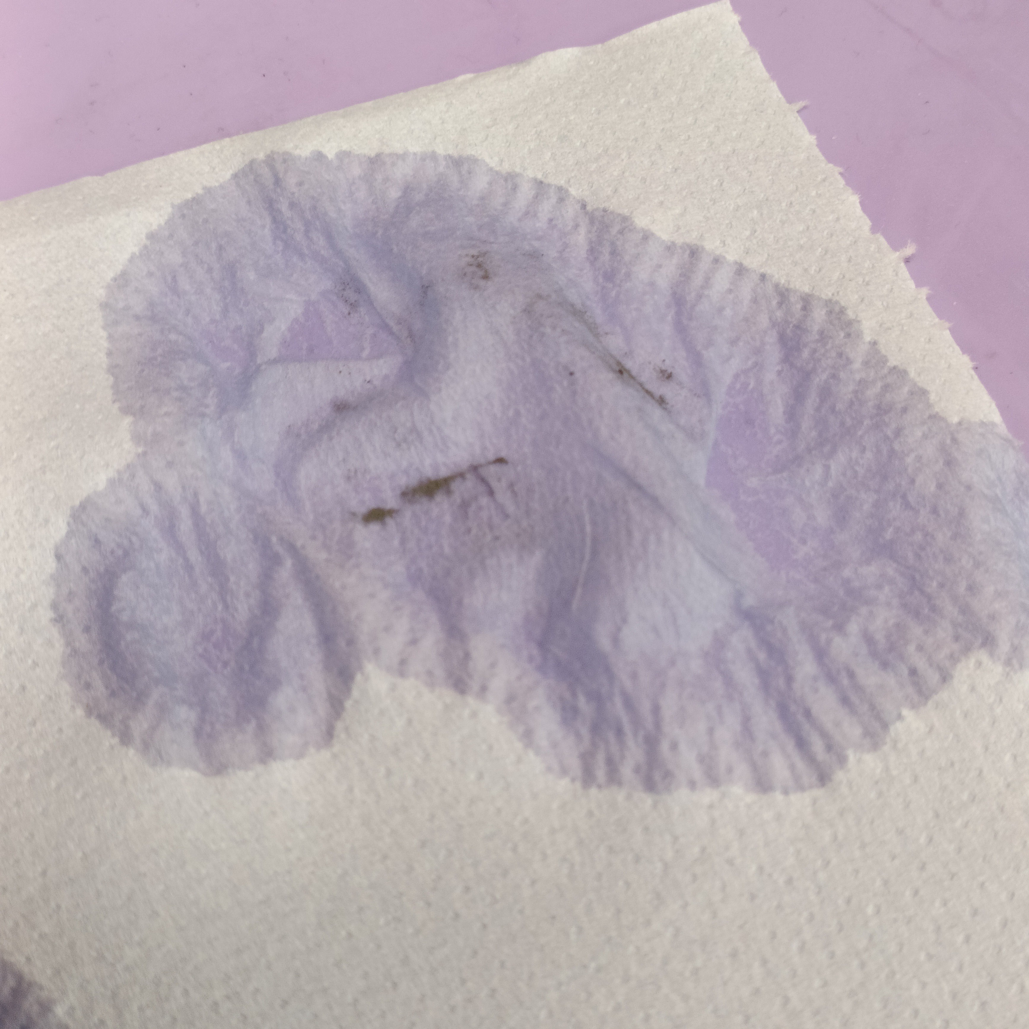
I tried both upside down and rightside up orientations, and did a few sub-5 minute attempts before letting it run for 2 rounds of 10 minutes at 40C water. When it was finished, I'd put it on a paper towel and a small amount of powder would come out:
Meanwhile, this is all the powder that came out of the pickaxe floss method:
Day 3
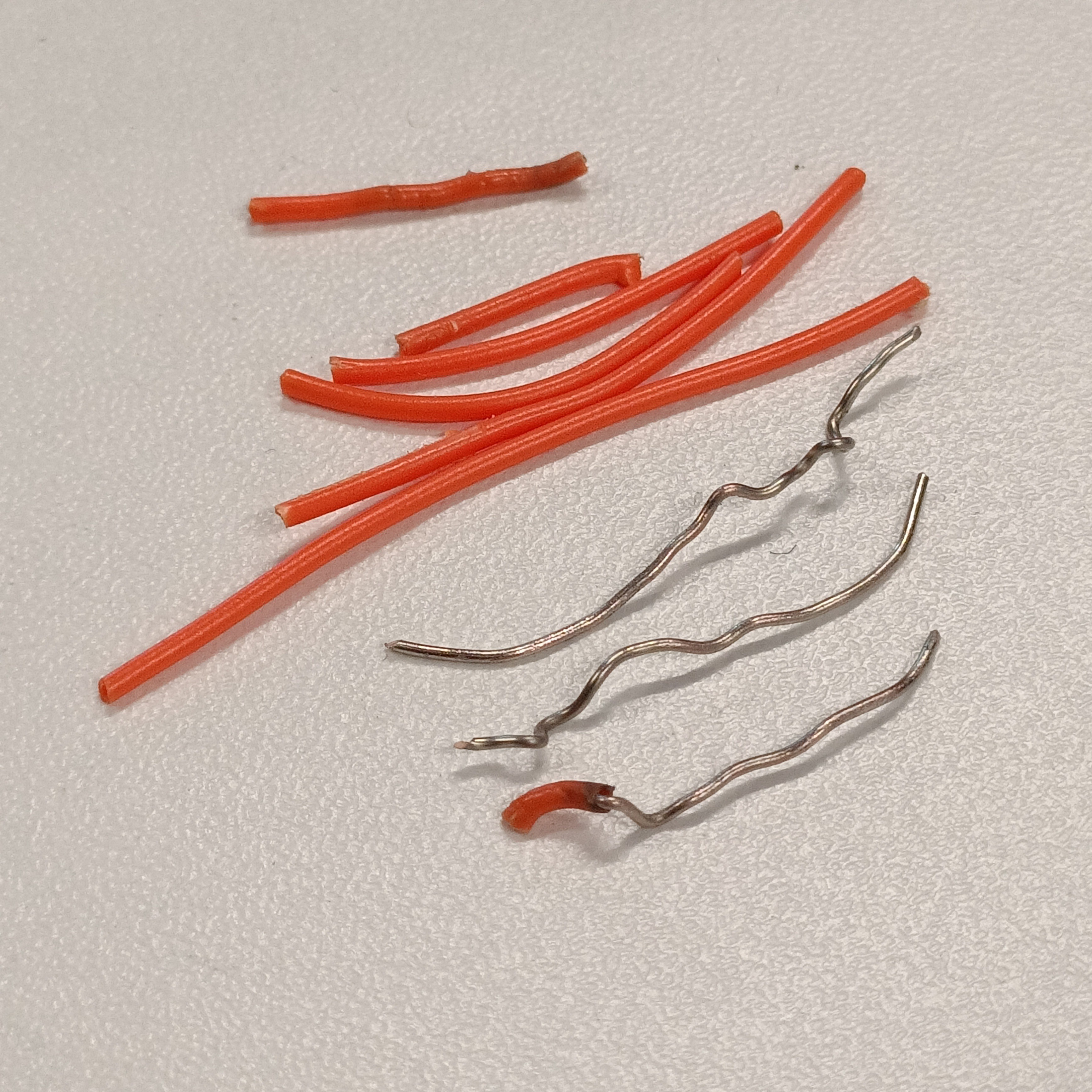
The strategy was to find and strip some stiff wire and mine inside the dry c8or while the wet c8or was inside the ultrasonic cleaner for 23 minutes at a time at 45C.
I cut and restripped when the wire was getting too crumpled and I feared it'll break whilst inside the c8or.
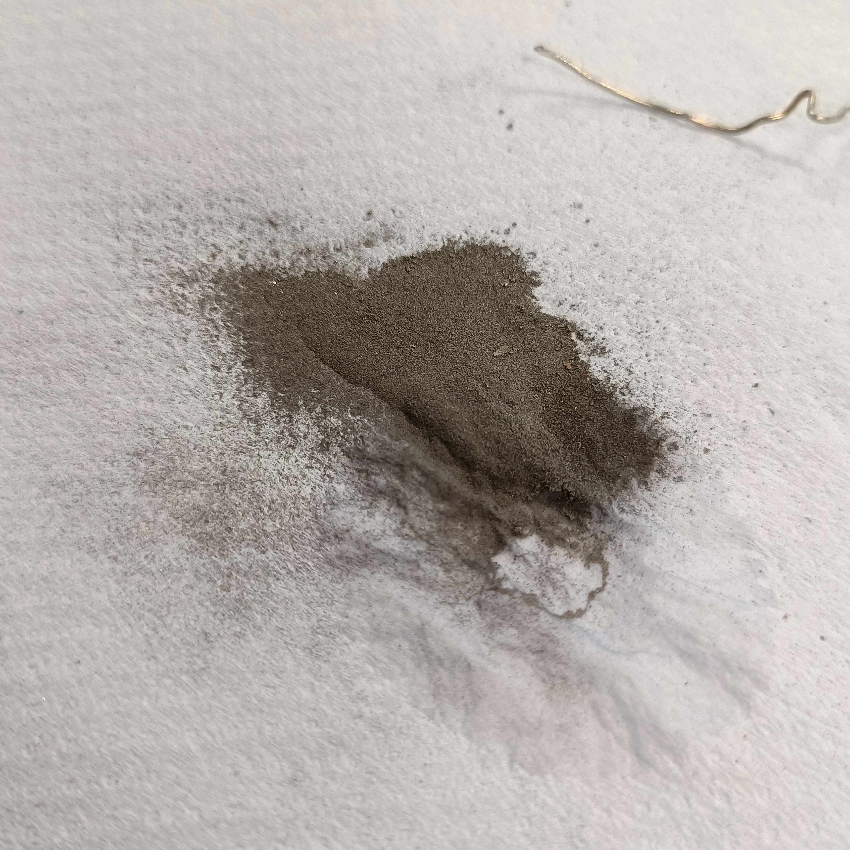
This is what I got from 2 ultrasonic rounds:
This is what I got by mining in the same timeframe:
Lastly, I put a drop of water on the dust to confirm that the powder does stick together when wet:
Future Work
My next strategy is to boil or superheat the wet Coaxial8or. Since it seems that the water can barely weave through the powder, the idea is for it to act kind of like TNT by causing it to turn into steam and expand from the inside.
On a similar vein, I could block the channels with water already in there and freeze it, potentially generating more pressures than what I can physically accomplish with a syringe.
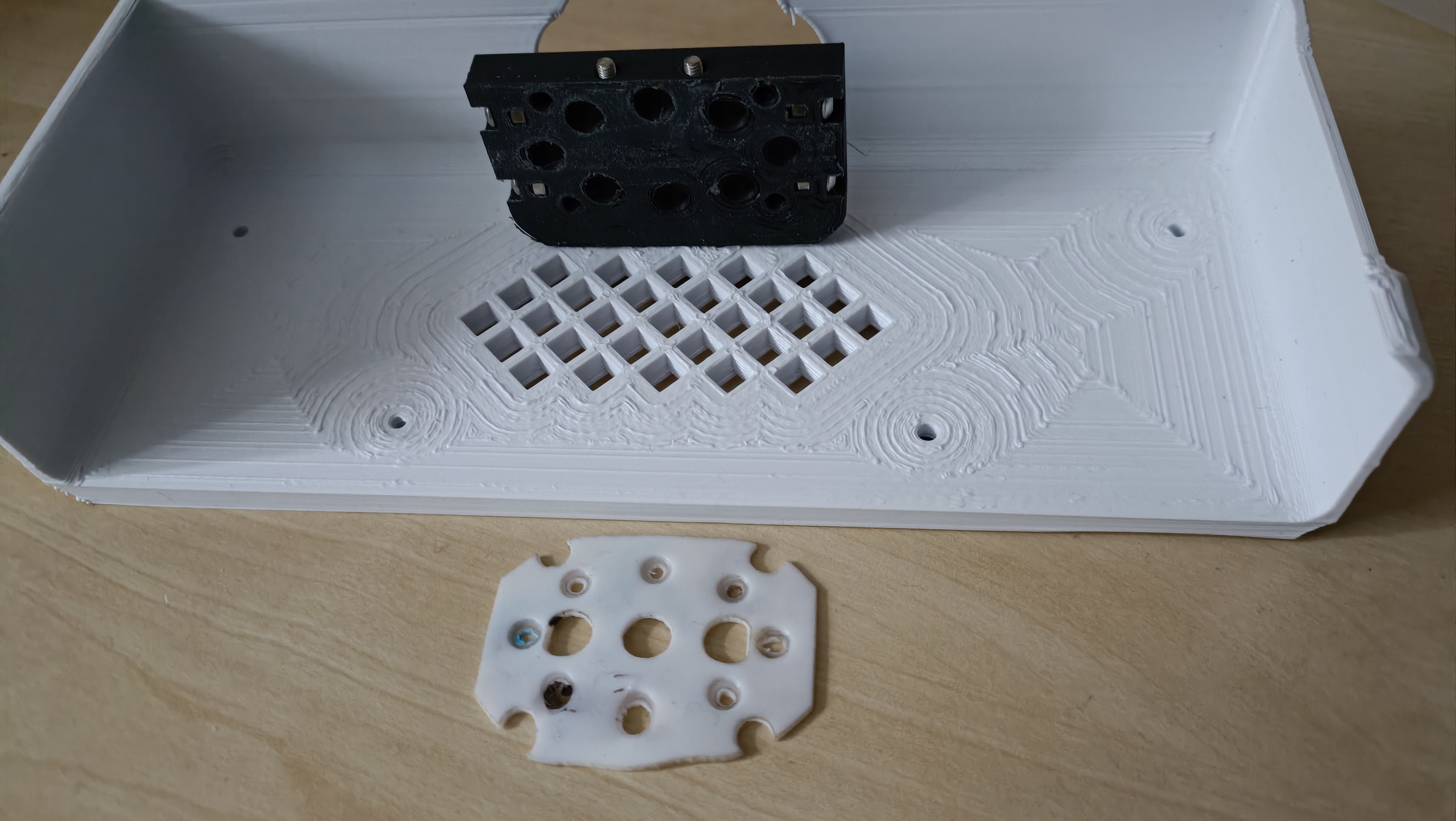
I envision a merge between the small heatsinks and the Bambu Lab heatblocks (see below) as a way to be able to turn on and off different inputs. Something like 10 watts should be enough.
This comes after I spent some time yesterday putting the heatsinks in fresh-out-of-the-kettle water to be able to get the PETG out of them:
I believe that the temperature doesn't need to be too precise, and that it might even be sufficient to simply connect the heater to a thermal fuse to have both quicker heatup times and a bang-bang temperature control. An example could be a 200C thermal fuse that resets after it cools to 170C.
Even this might not be needed, as if I recall correctly, ceramic heaters naturally have a temperature limit due to increasing resistance at higher temperatures. In that way, it may be possible to design a heater that quickly reaches equilibrium at 200 - 210C, which is the maximum temperature Deckingham needed for the majority of his material tests.
In this way, only 9 wires would be needed to implement this, there would be no moving parts, and the potential for unused channels being clogged would be minimised.
I needed to go back to tap the thermistor thread in one of the Coaxial8ors and, while I was doing that, I thought "I just need a pilot thread to get started and I can be on my way", referencing to tapping the plates. I soon had the idea to print such a jig, but first I tested the idea out with an M6 bolt and learned that I'd need to consider how to keep it in place.
Me1: If only I had a plate with a bunch of starter threads. Then I could put them both in a vice.
Me2: We have plates with starter threads at home.
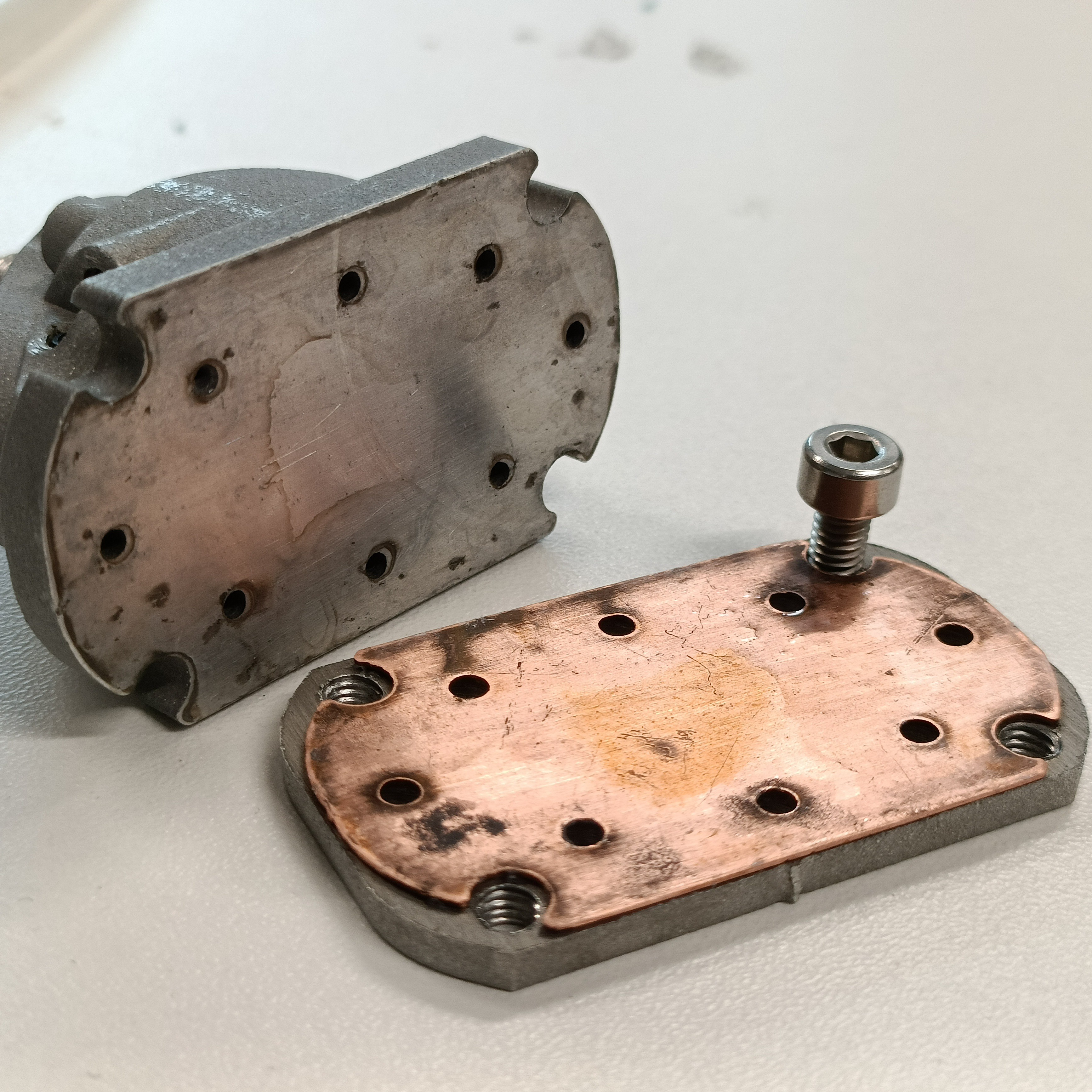
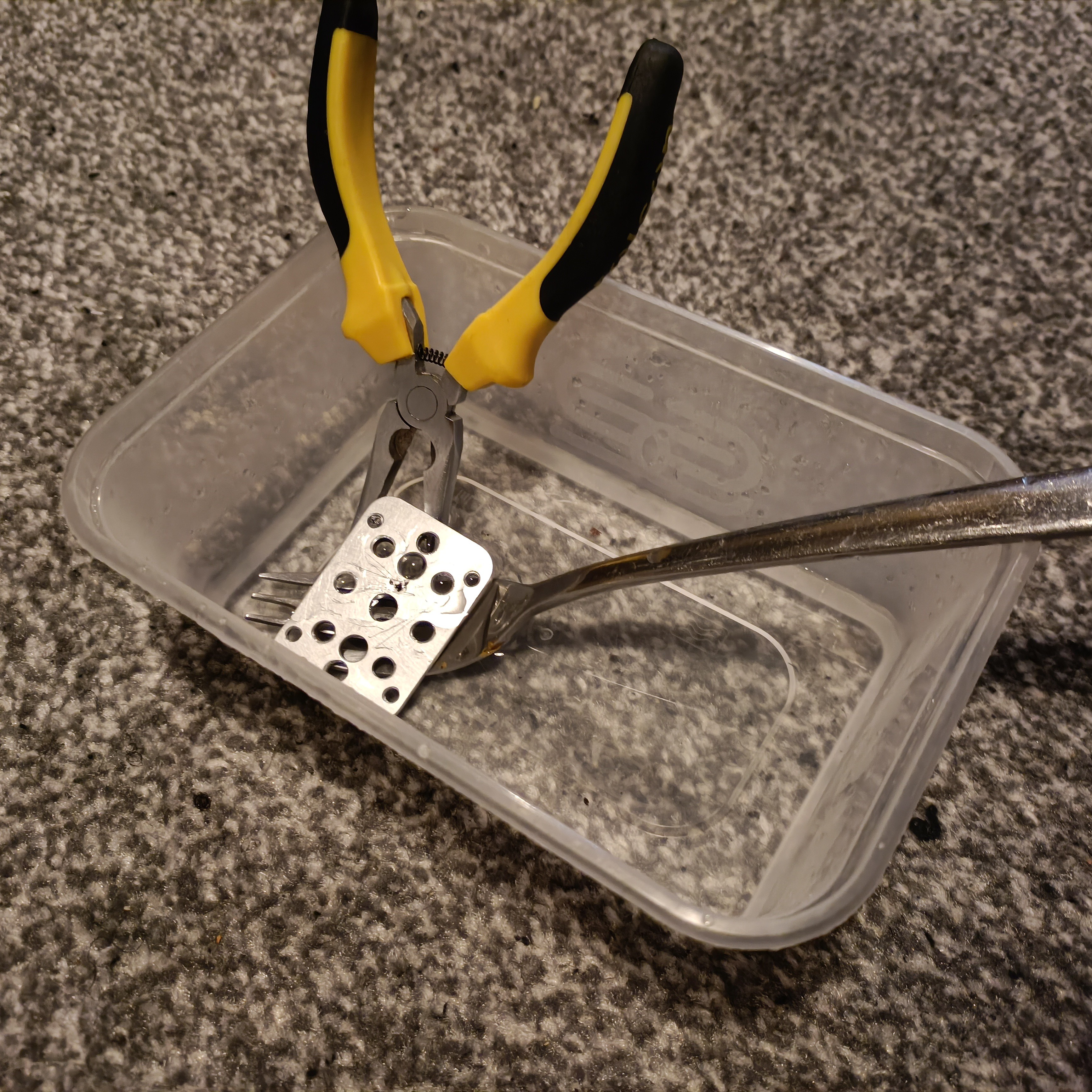
The plates with starter threads at home:
Yes, I retrieved and cleaned up the clamp plate from Coaxial8or r0. I pried off the plastic and cartridges from the clamp plate, then put it in the above tub along with a shallow amount of kettle water so that the PETG softened and I could clean off the rest.
Then I asked for some new plates to be cut, where the holes in the CAD were offset by 0.05 before being exported to .DXF for the waterjet:
I again got a 3rd set as a spare.
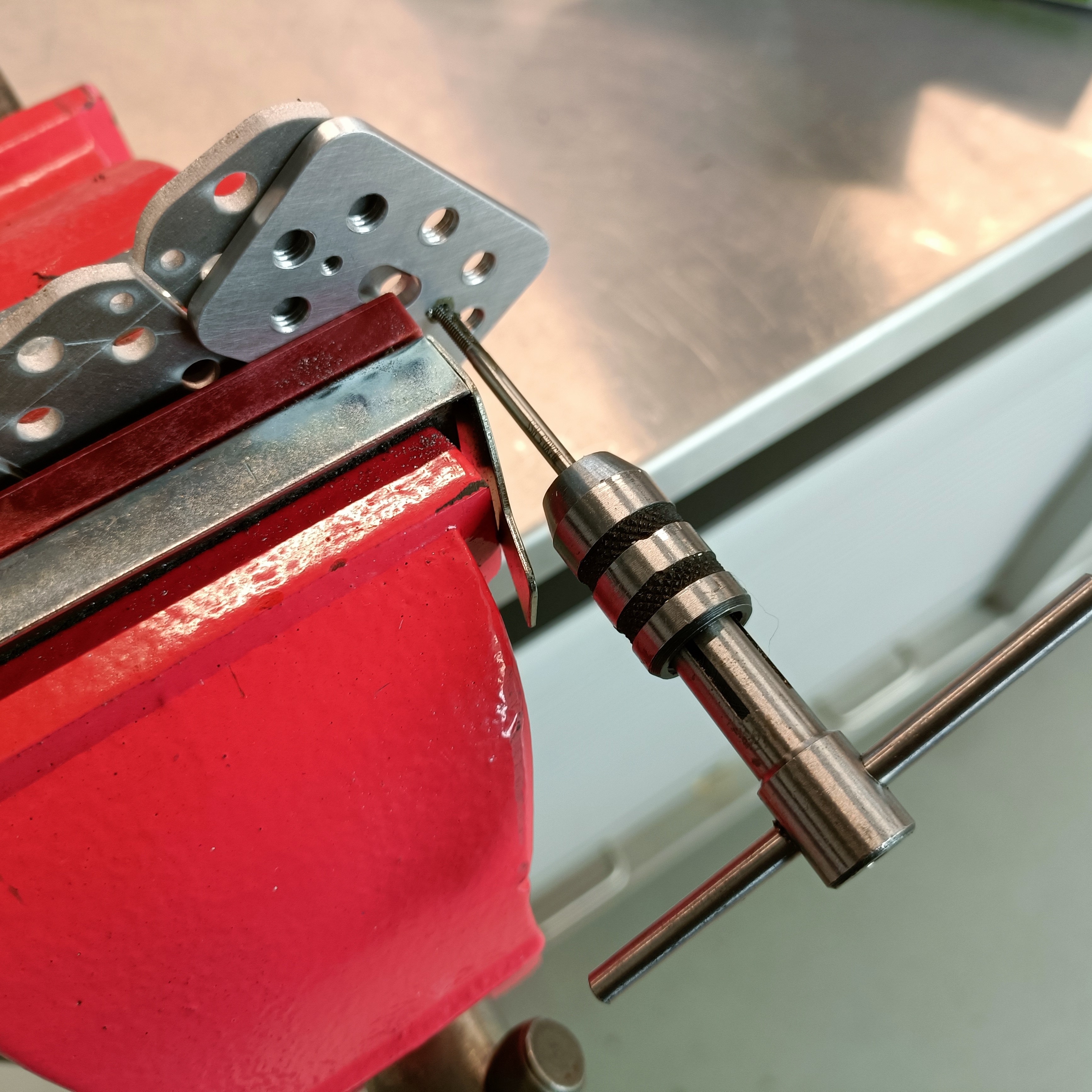
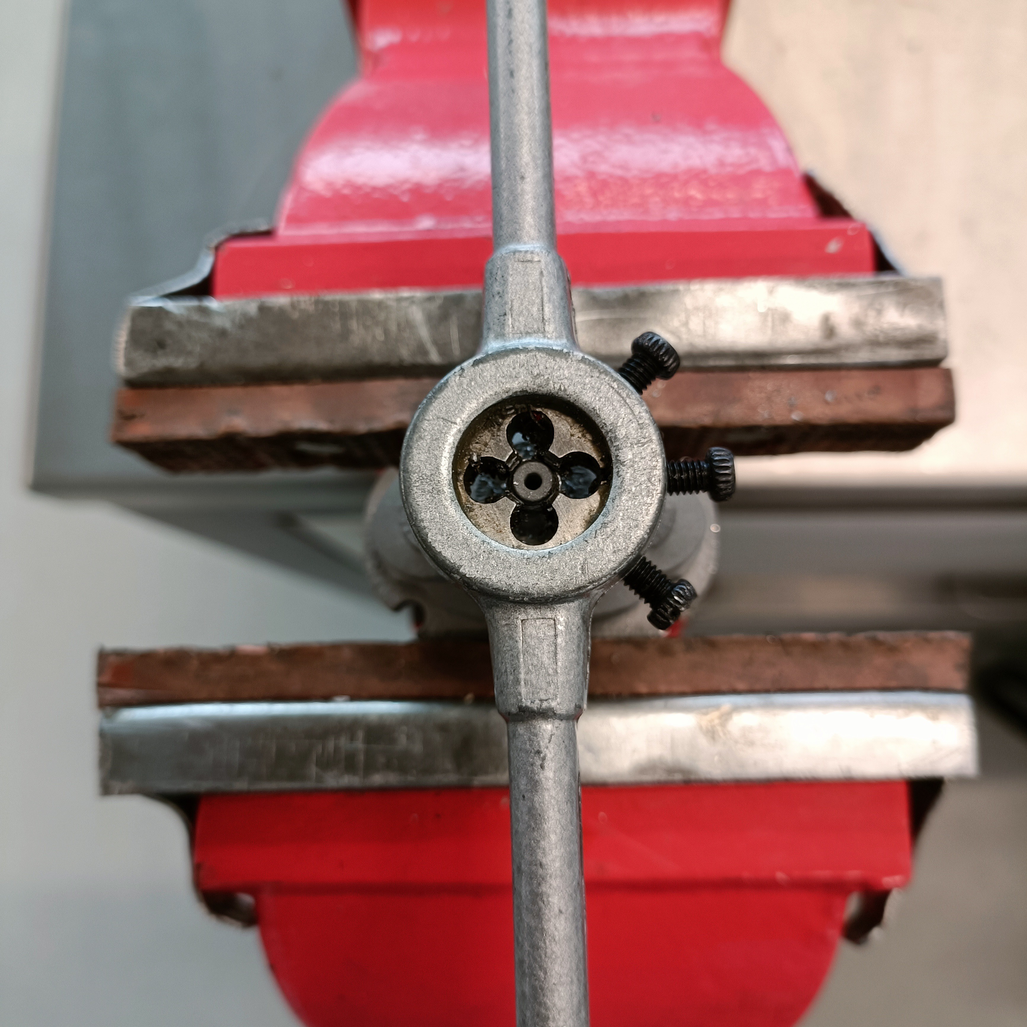
I started off with the M3, and seeing that worked, tried a pilot M6 which seemed to work too. Thus, I switched back to the M3 tap, broke off a plate and threaded all the M3 holes on the new coupler plate.
Me testing the M3 tap.
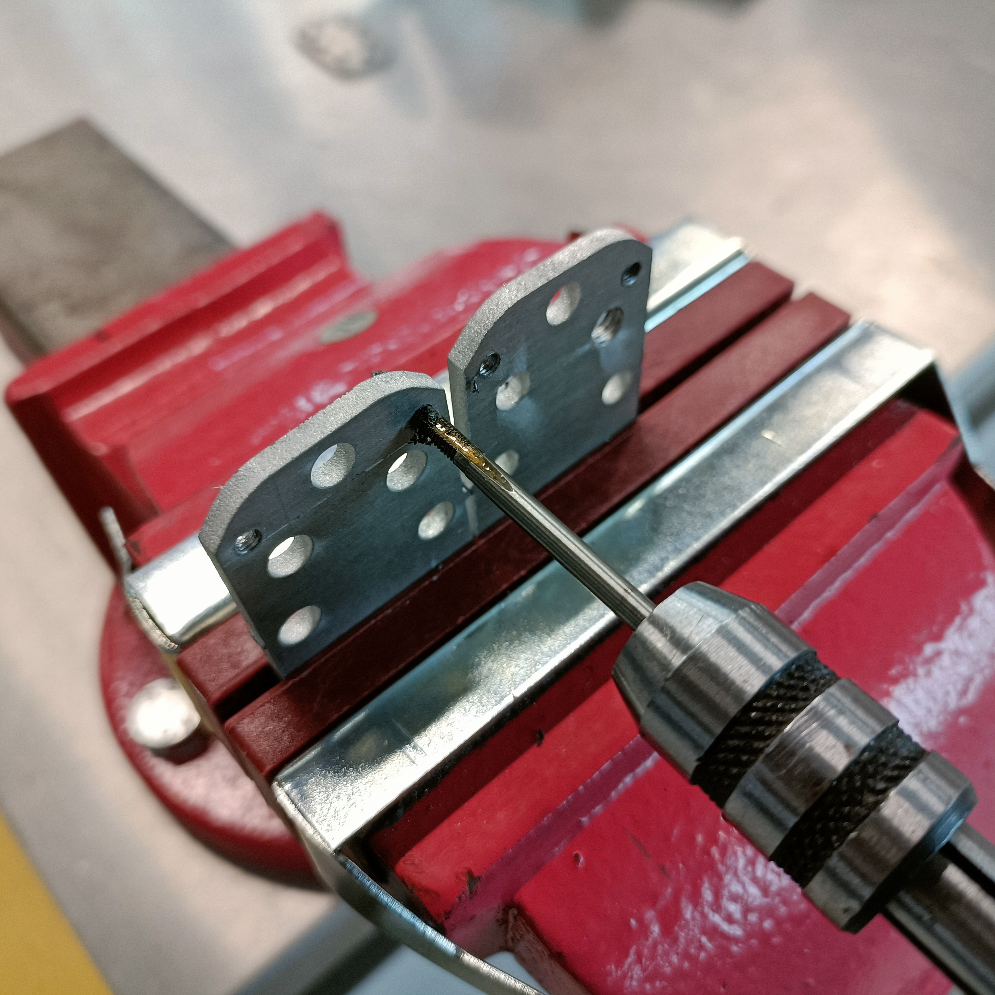
I started the threads using the old coupler plate, then went back to finish them:
This plan all changed from the M4 tap, where the starting tap doesn't actually finish the threads like the M3 one. Only the finishing tap cuts the threads fully. I couldn't even properly thread in the finishing tap into the starter threads, so I instead decided to just use the finishing tap and fully cut the threads in one pass.
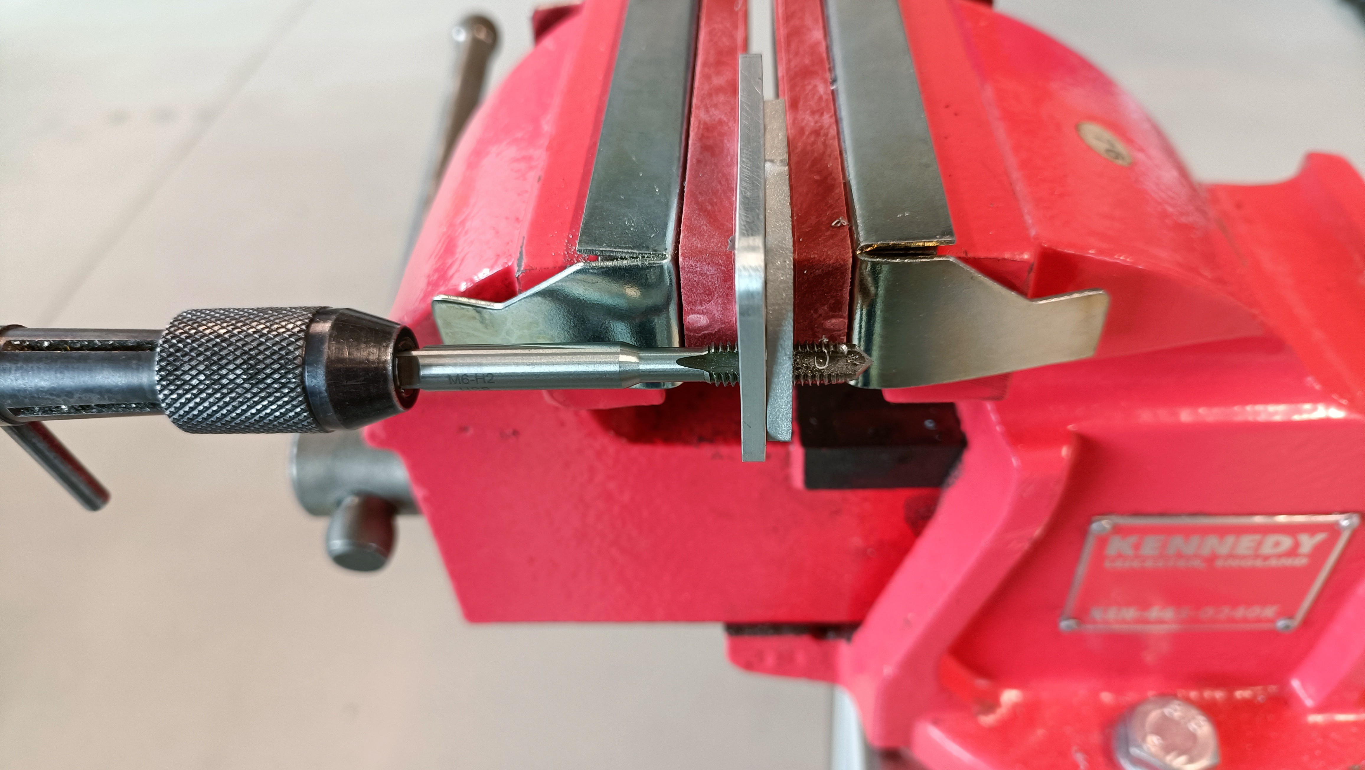
By the time I got to the all-important M6 threads, I had a strategy:
Get the tap into the cloner plate.
Align tap with the hole so there's no XY jiggle movement but the plates don't have a gap in them.
Place in vice.
Turn about 4 - 5 times.
Turn back by a quarter.
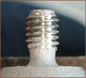
Turn until there's like 4ish threads left visible on the tap (see image below)
Turn back till about 2mm of the tap tip is visible.
Then you slowly turn until the tapping plate comes off.
It's then faster to start the next one because the tap height is approximately enough to have the two plates flush and there be no jiggle with the untapped hole.
Then it feels like a candy crush level selector as I go though the other 7 holes.
It took me 35 mins to thread the M6es of 2 plates. I think I switched to a new cloner starter tap every 12 or so threads to make sure that the tap was still going in straight.
Keep the threading hole close to the clamp to reduce the chance of the two plates bending apart from each other.
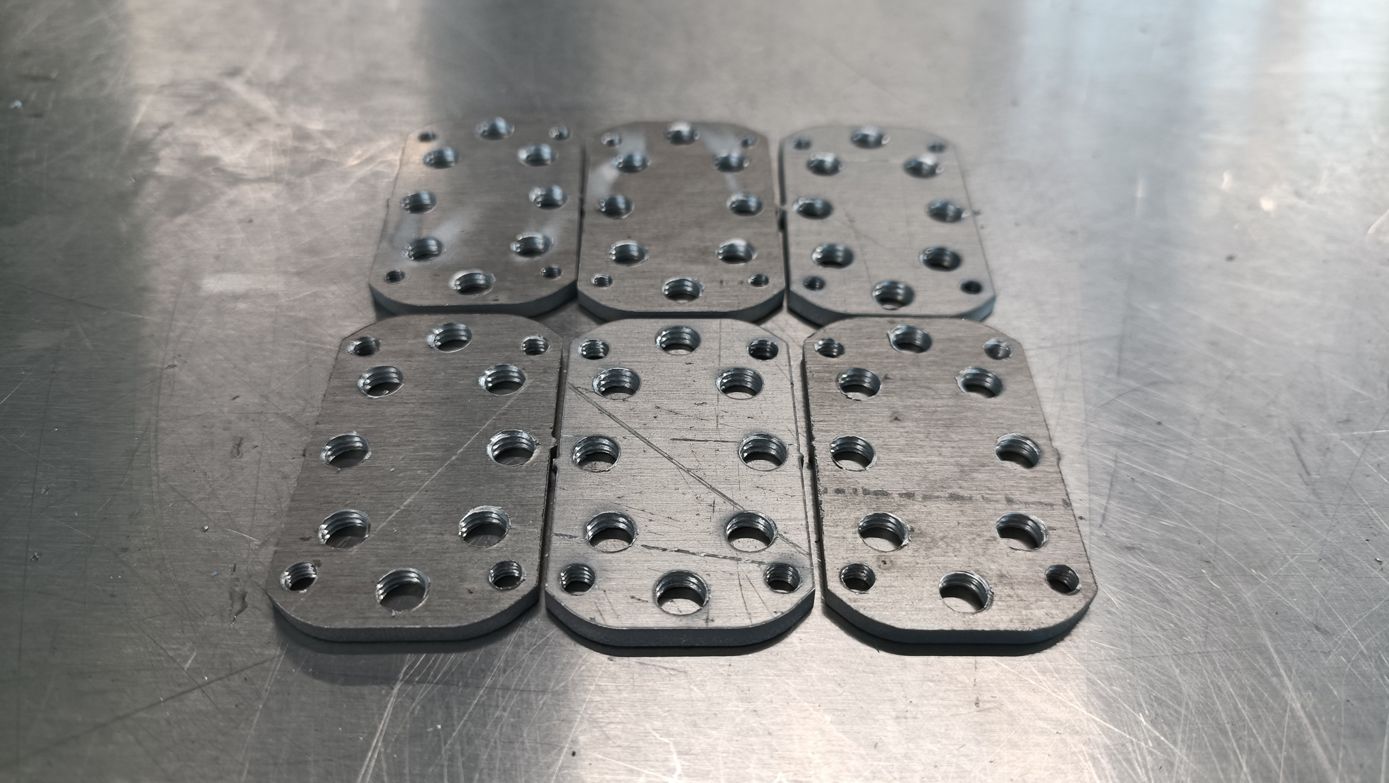
This is the result:
Surely there's probably an actual specific plate that allows one to hand tap perfectly straight, but I don't know what it's called (or if it even exists).
In other news, I also printed the new holder+cover, and saw that the PTFE gasket actually got squashed thin from the top side:
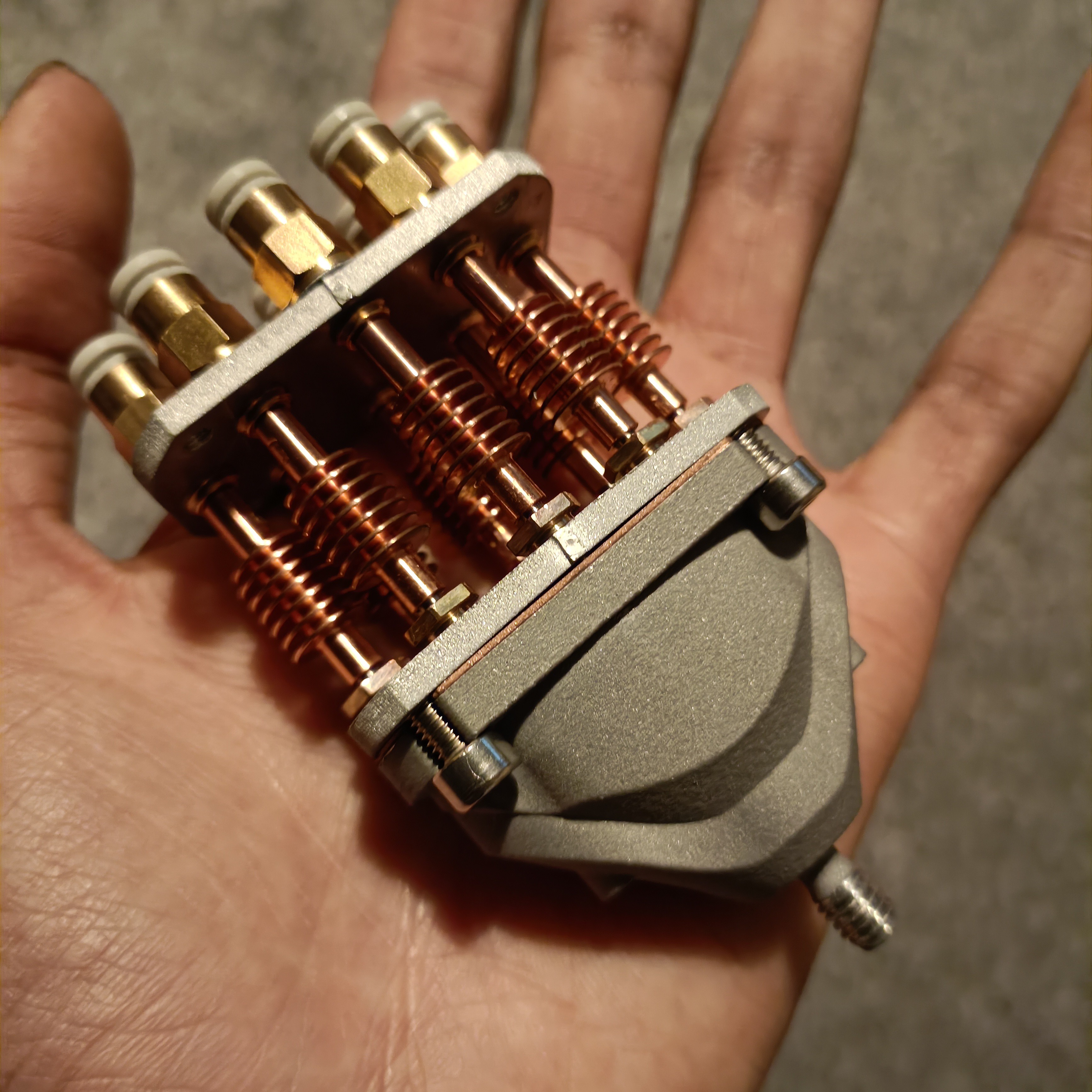
[May 22] It all goes together, so this strategy seems to work at the moment:
The Coaxial8or is also compatible with a 15mm aluminium spacer. I've only got 9mm and 6mm spacers though.
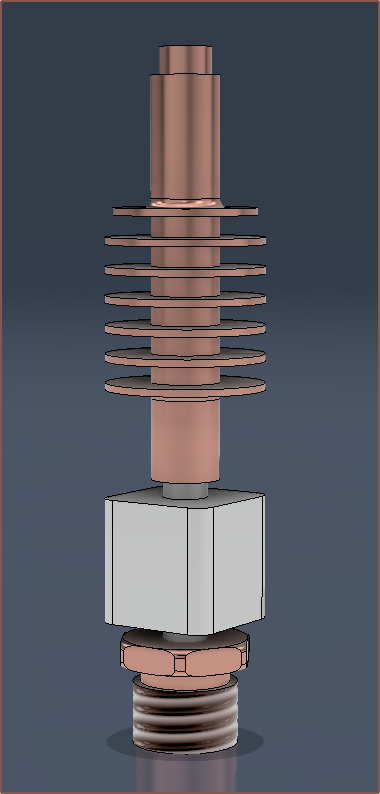
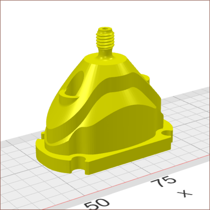
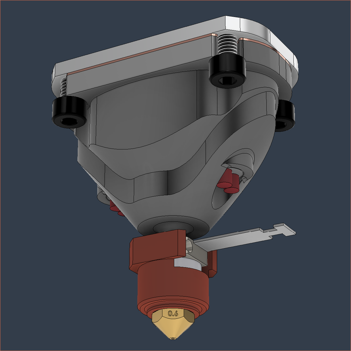
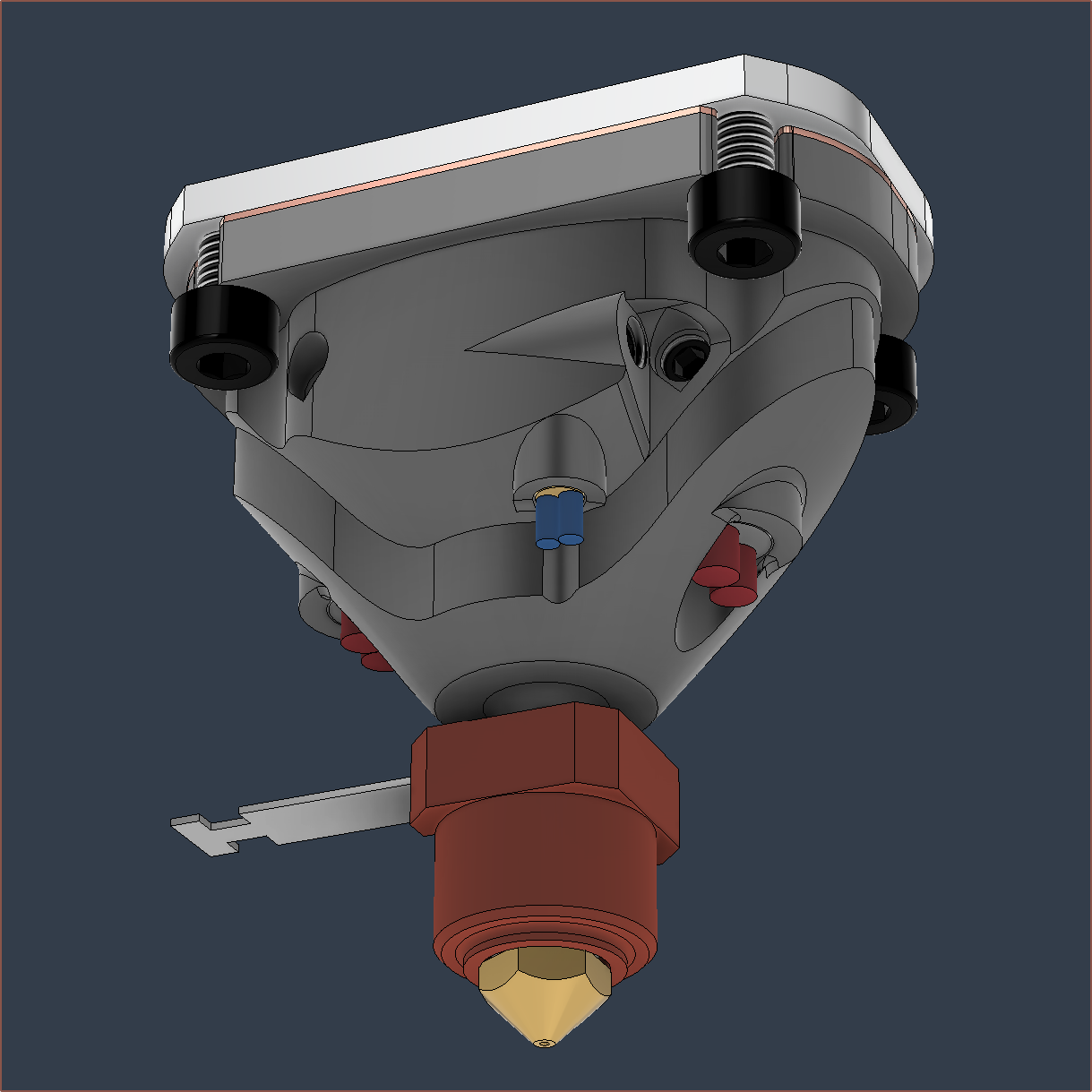
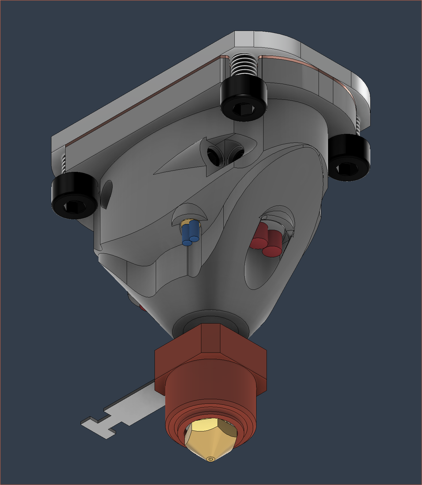
Also finally got some new project renders with LED rings that better shows what the hotend is trying to do.
I've gone through and updated the printed files (and the render LEDs to better represent what this hotend is actually doing).
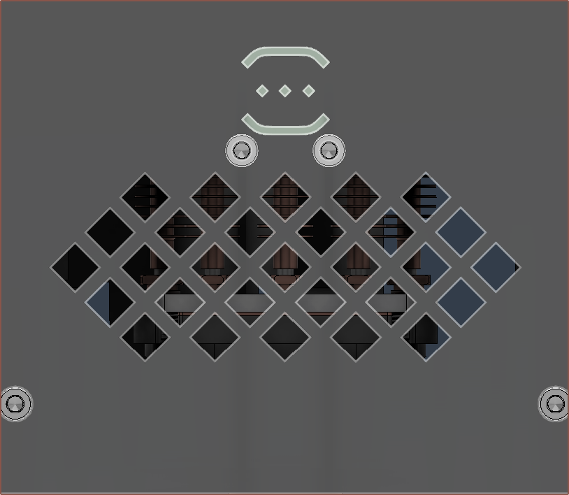
I have changed the grill so that it's easier to see if there's a leak happening on the main gasket. Since this makes the cover look top-heavy, I've moved my logo to the top (which resembles a spool on bearings).
In other news, the grub screw for the thermistor successfully works on one of the two Coaxial8ors so I'm going to need to re-tap the other one.
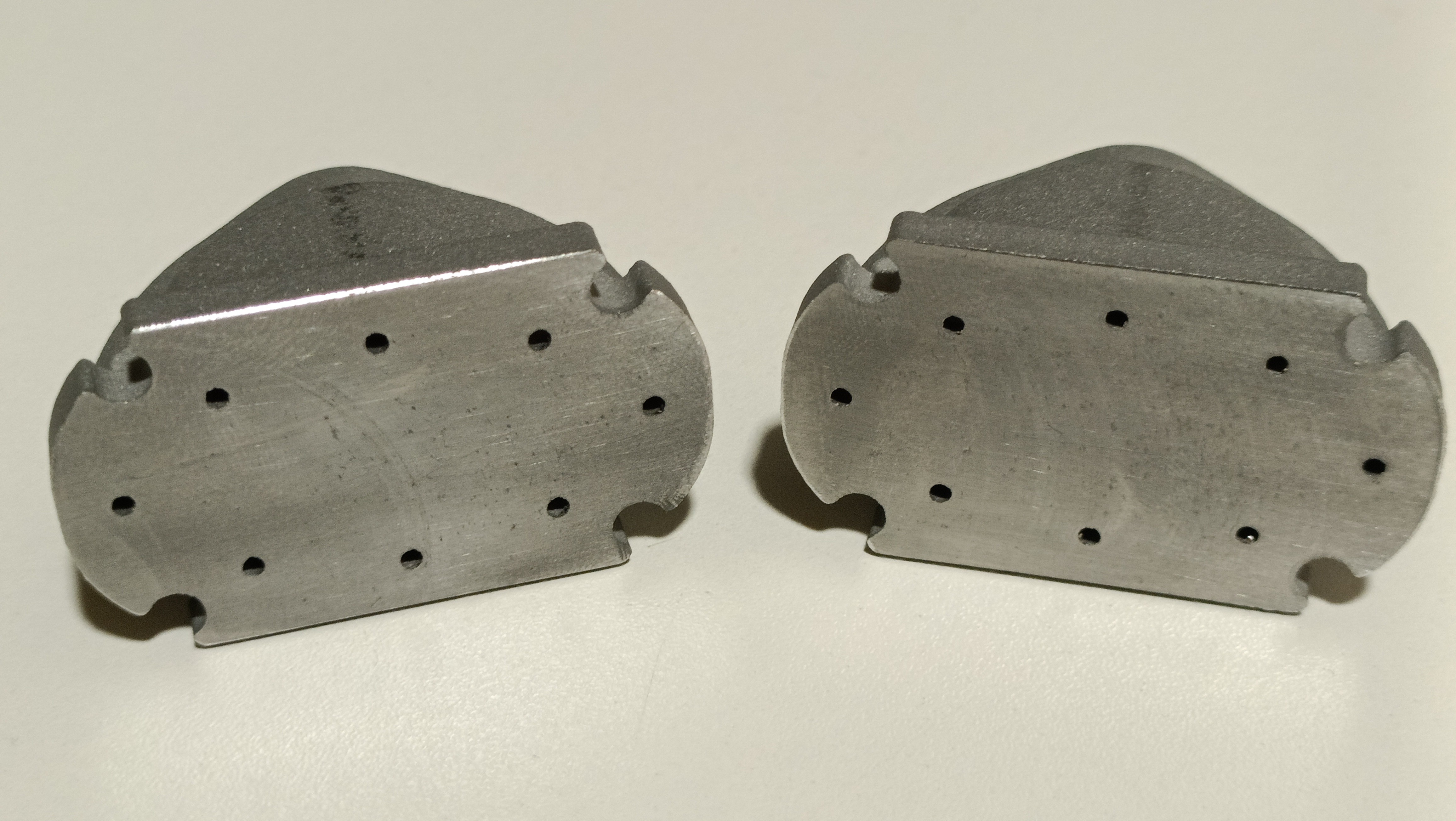
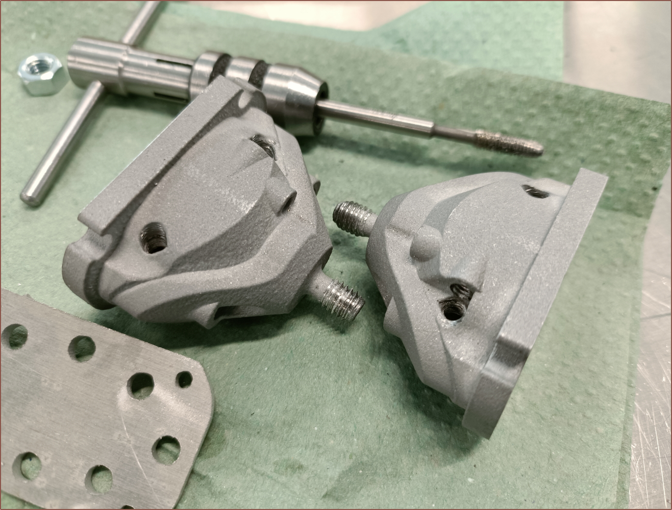
The machinist technicians just happen to be quite busy at the moment, so I only asked them to mill the top faces.
The nominal thickness of the clamp block section is 4.65mm, meaning that it must've been even thicker than the 4.5mm modelled in CAD beforehand. Perhaps the engineers at PCBWay read the review I left for the c8or r0 and thickened it slightly.
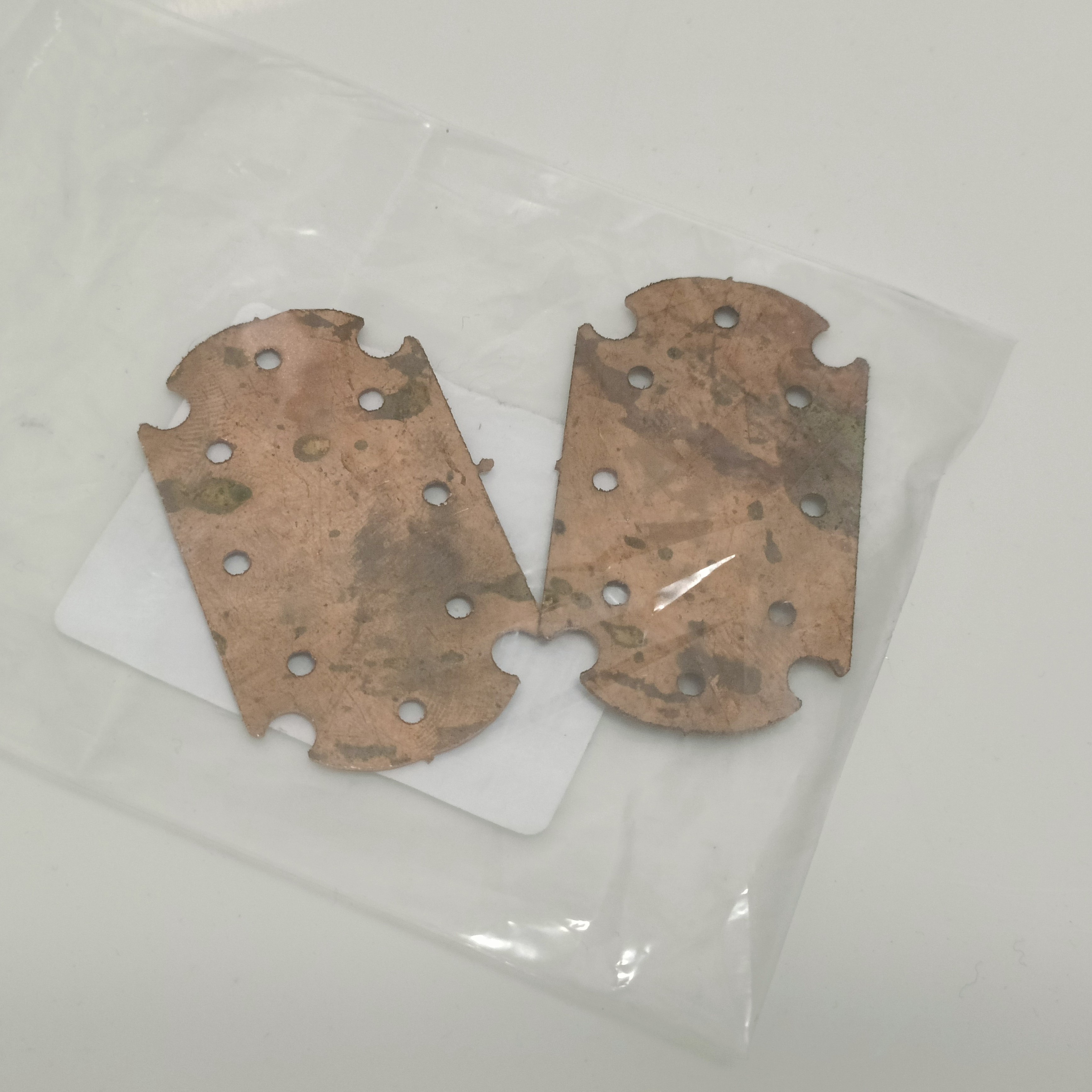
Then I went to the waterjet technicians to ask for the flat parts such as the clamp plate. They just happened to have a small piece of 0.65mm copper that was large enough for 2 gaskets:
They have very sharp edges. I plan for those edges to point up into the clamp plate.The technician recommended that I undersized the holes -- due to the tapered walls the waterjet would create -- and then drill then tap, so I offset the faces by 0.25mm.I asked for 3 sets so that I could have a practice round.
I'm thinking that I should've just left the sizing as is, because the taper through 3mm aluminium is very minor but now the holes are too small to just tap directly. I'm likely going to just wait either until the techs have time or I print a jig or something like using a pillar drill, as I don't think I'd ever get all 32 M6 threads tapped perpendicular to their faces. Worst case is just ordering more parts from PCBWay.
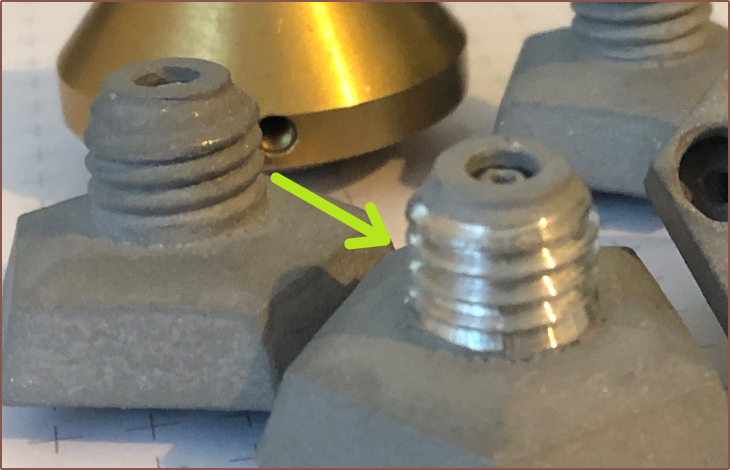
The M6 threads took a bit of careful consideration to get started, but I only got the threads to bite in one location meaning that it likely was going down the printed threads.
The finished thread certainly looks better in c8or r1.
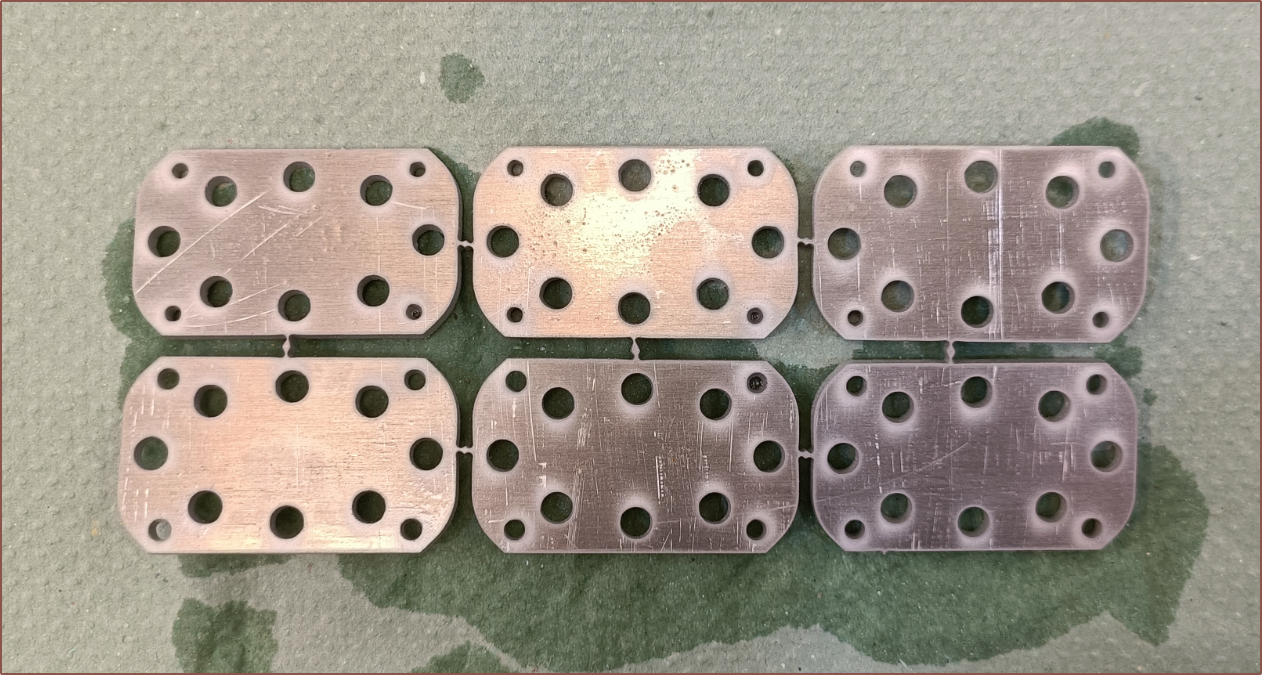
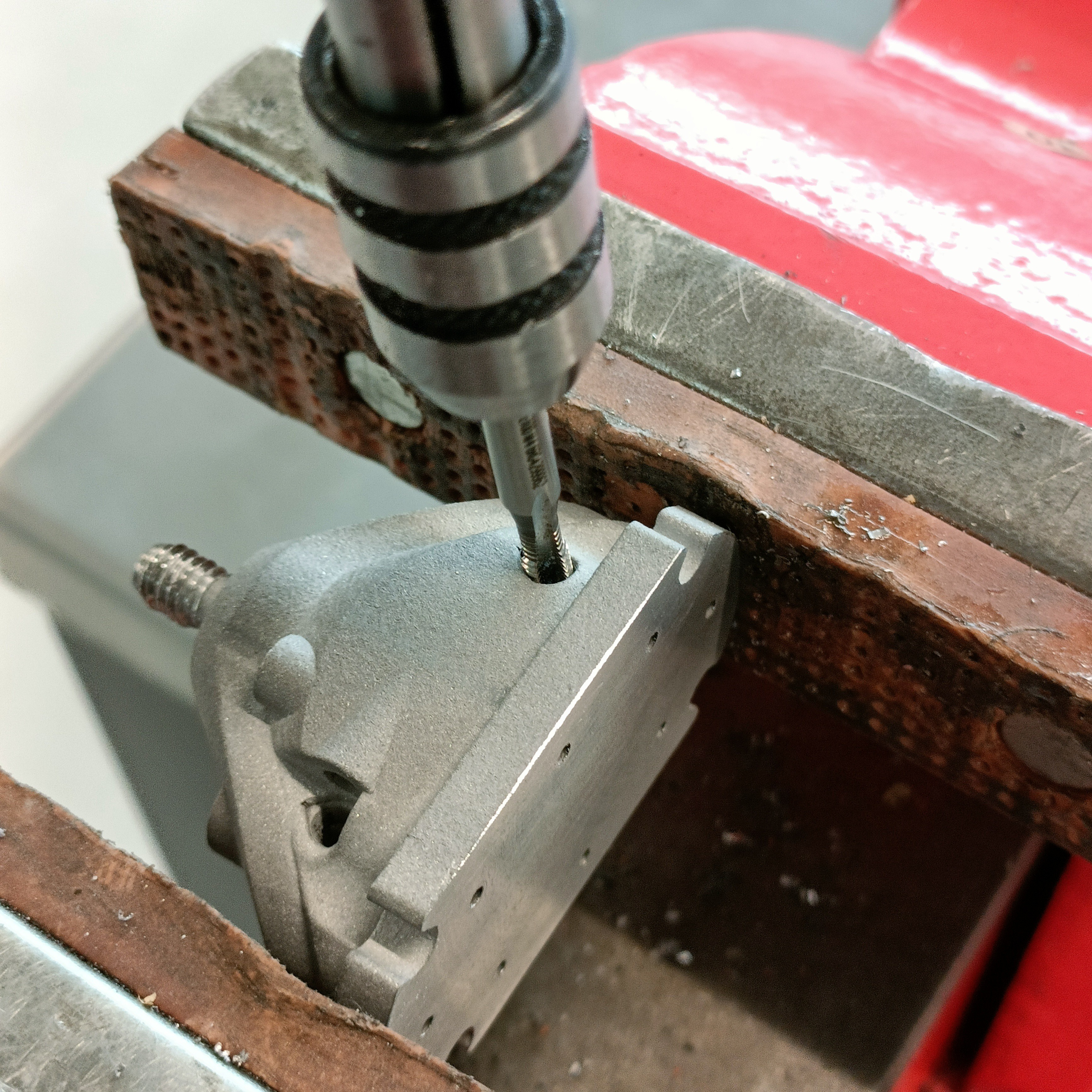
Lastly, I lined up my eye directly over each of the M4 holes to tap and used a fiducial marker like a shadow or tip of my foot to mark the horizontal line (to account for my head slightly drifting) and then placed the tap directly over so that I could account for any 2D angle errors.
I used a long tap to get the threads started and then a shorter tap (see below) that fully cut the threads. Well, almost fully cut them in the case of the thermistor. I haven't tried yet, but I'm hoping that I can finish tapping with an M4 bolt and an Allen key.I like the milky greens and silvery greys in this image.
So far, it feels like the 2-for-1 offer is paying off, such as the confidence / peace of mind of knowing that I've got a second life if things go pear-shaped. I still haven't dealt with the powder inside them though.
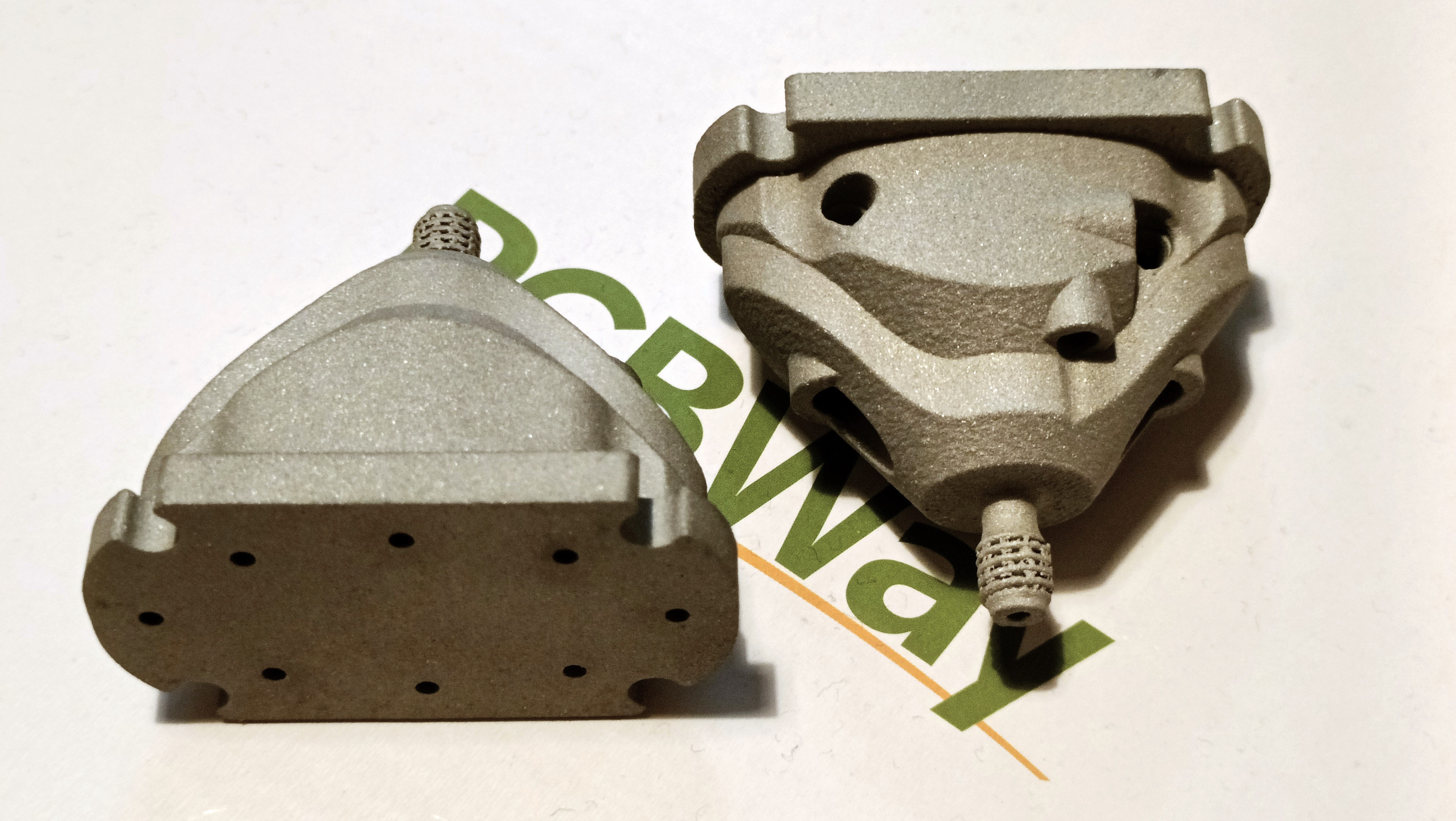
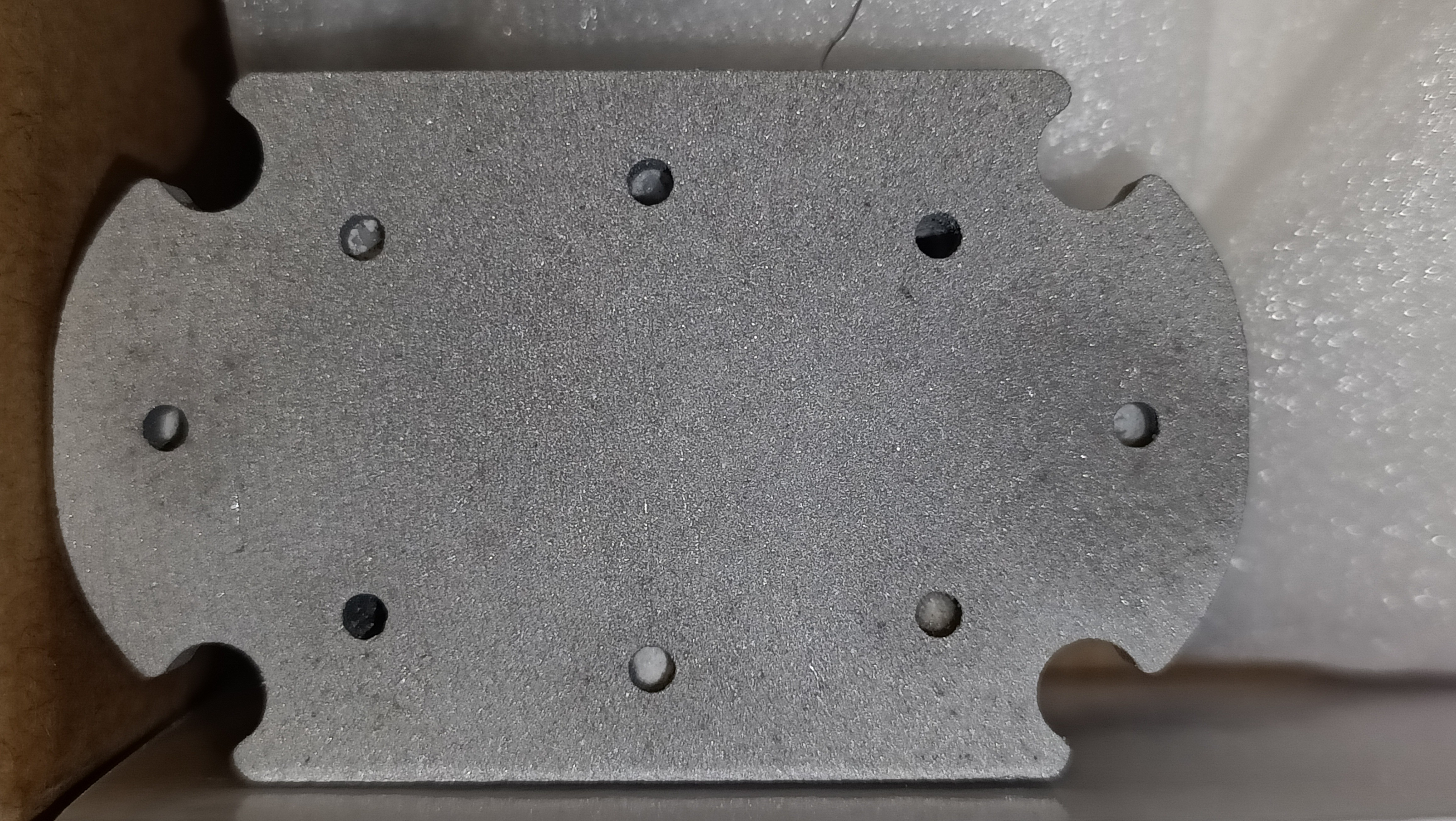
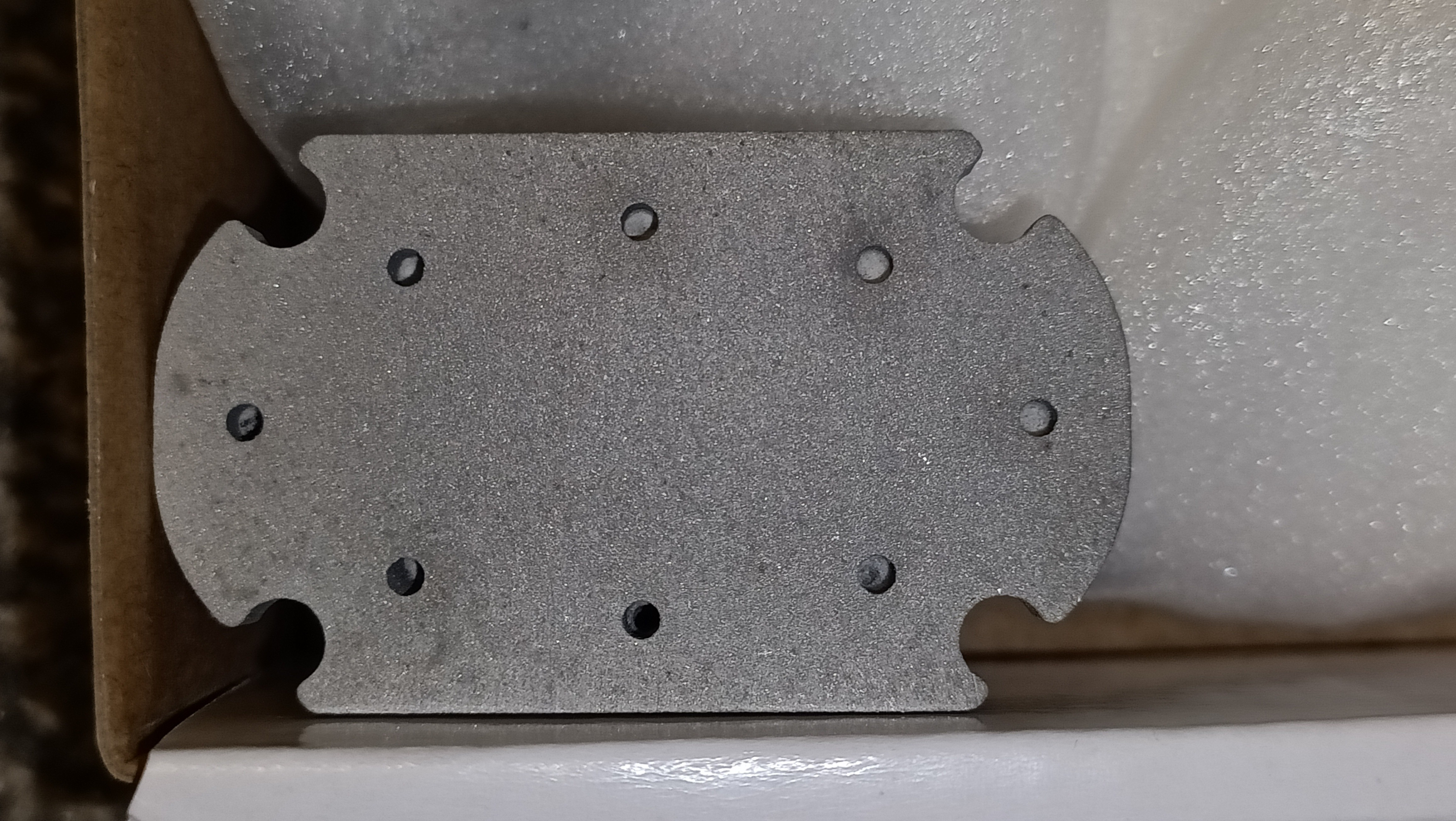
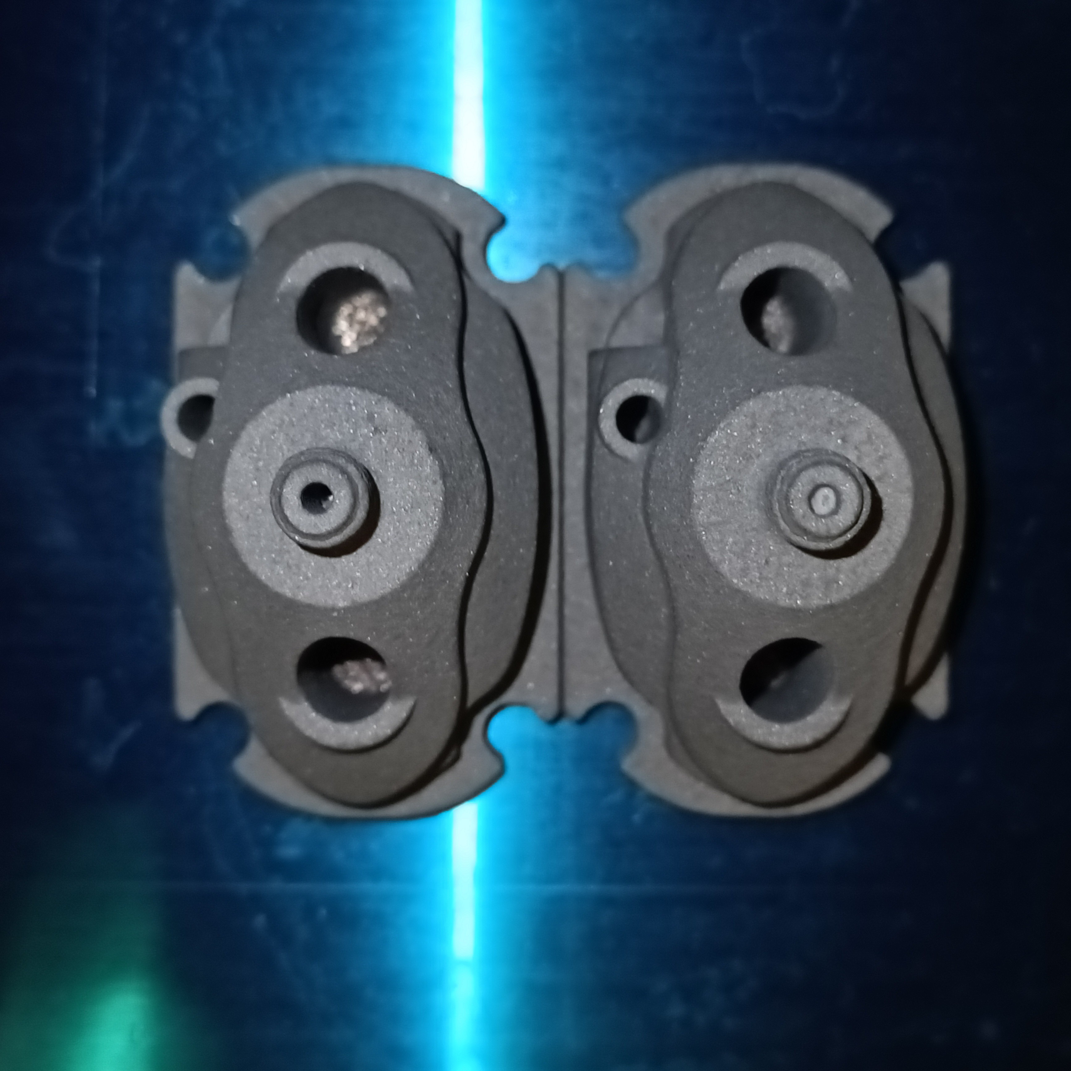
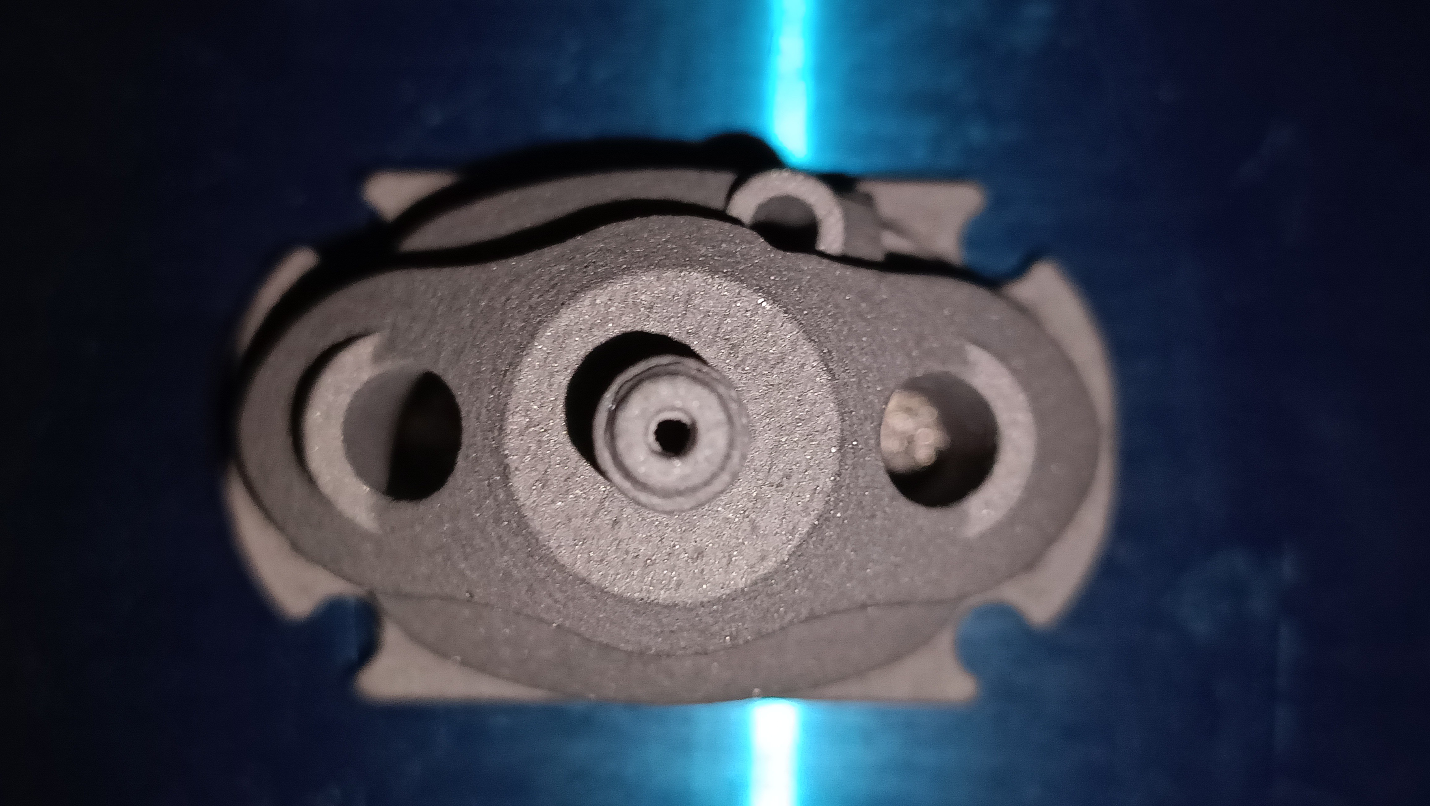
The prints have finally come in and they look as expected (because I had stared at the CAD model for hours making sure everything was right) and the dimensions are good (1.75mm input holes, even less warping than the r0 print, cartridges slide in nicely), but there's a problem:
As you can see, both prints seem to be like completely blocked. As you might be able to see in the second image, I don't think they're "welded shut" or anything, because poking with a toothpick has put some indentation in the lower right diagonal one. One of the prints is 53.2g and the other 52.7g, so it seems that the quantity of powder in them are different. At least I've got 2 so I know it's not a one-off.
This is how I received them.This is after I poked the right one with a toothpick, wanting to probe how deep the seeming blockage is.
Not sure how best to proceed. The channels have been modelled larger and shorter than Revision0 and yet powder has been left in?
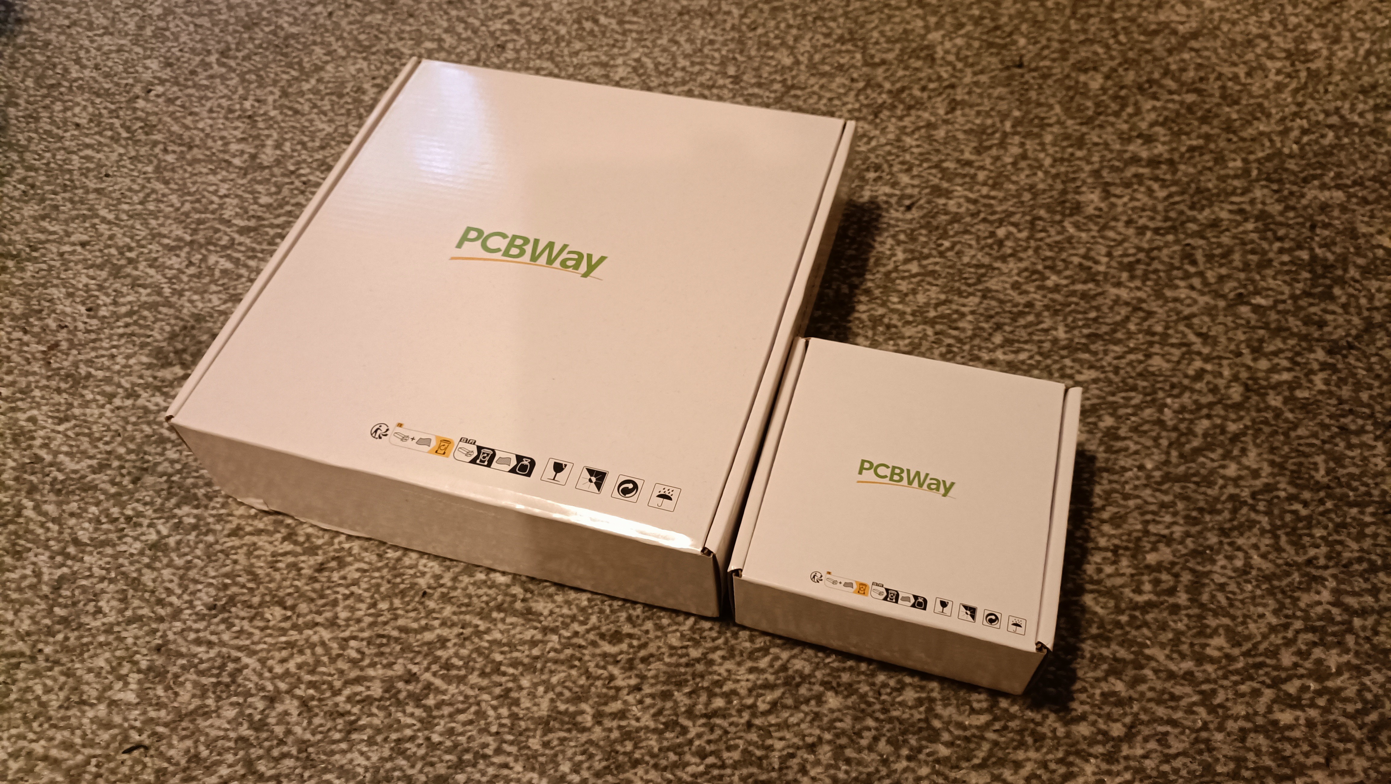
In related news, the box these double c8ors came in was half the dimensions in XY and ever so slightly shorter in Z, suggesting that perhaps the Coaxial8or r0 was just a tad too thick for the smaller box and that's why its shipping was double.
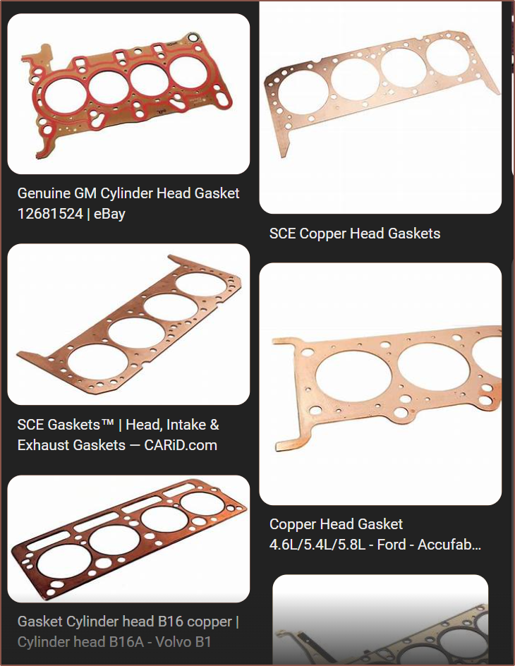
I've also remembered that I should be looking for a gasket material, and was considering brass when I was searching for a copper sheet, but copper gaskets are a real thing (unlike brass it seems):
According to this article, copper was actually "one of the very first materials that was used in the gasket industry".
I got a "$5 off over $49" coupon for filling out a survey
After some messages between Me <--> Service Rep <--> Engineer, the quoted prices were $38.32 for 1pcs and $73.43 for 2pcs of the aluminium 3D print from PCBWay. The shipping cost hasn't changed at all, suggesting that the c8or r0 must have been just a bit too large and the system bumped it up to a bigger-package charge.
Now it seems that all my "sweat equity" into shavings has synthesised into savings, as I can now buy 2 c8or r1's for about $2 more than a single c8or r0.
In British Pounds, my cost for this specific order is approximately £64. 2^1 pcs of 2^3-channel heatblocks costing £2^6... what's the 2^10 going to be?
The new geometry is implemented into the design, and I'm still at 193cm^3 (52.0g). Heat-up times should be about 40% faster than R0.
Because I was trying to find more information about Construct3D's custom heatblock design that is targetting 200mm^3/s, I started listening to a podcast and one of the things that Jacob mentioned was "intent", describing how the quality of his Minecraft server building designs had much more quality when he had to struggle in Survival Mode to get every block, compared to Creative Mode when he has unlimited everything, and he subsequently brought this idea of intent over to his 3D printer design methodology. Now that I've got a new heatblock design and every millimetre of it has been questioned multiple times, I've been thinking of the similarities to Jacob's talk of intent.
Firstly, some quick changes that have happened in the design:
MinorChannels are now 1.75 * 0.75 + 0.2 -> 1.5125mm.
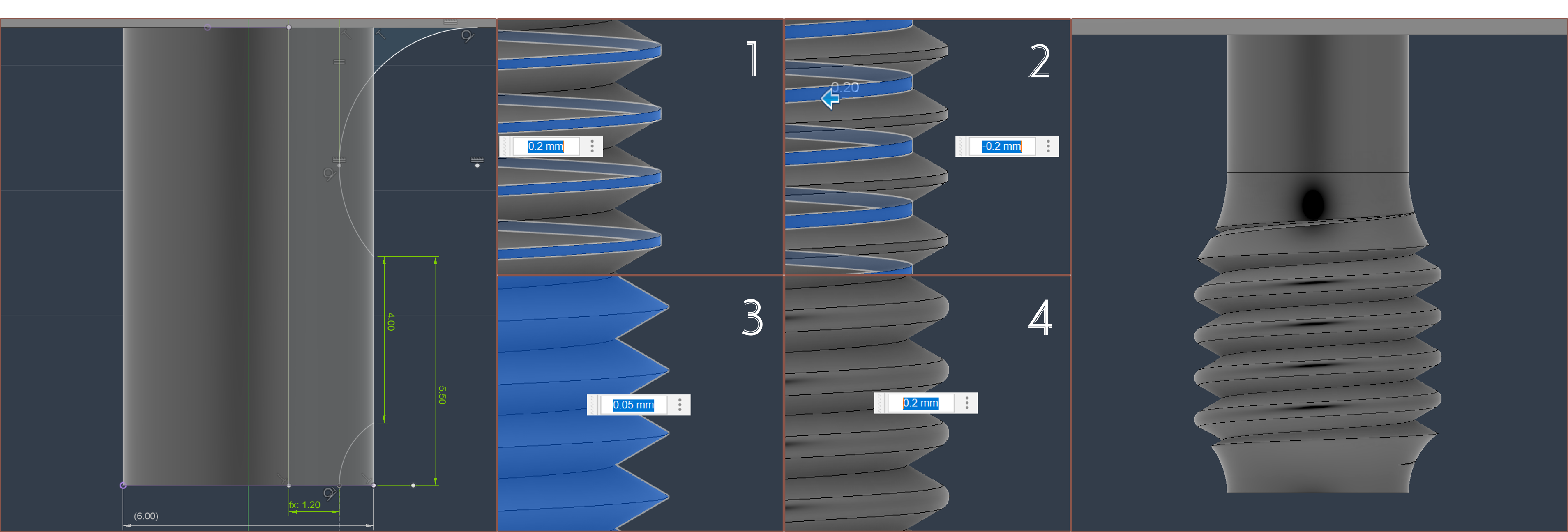
I've reduced the length of the thread and now it is 10mm (down from 12mm in R0).
The height of the heatblock is now 41.5mm, which is about 10mm reduction from R0.
The heatsink thread holes are 2mm from the edge, which should be ok.
Centre Pillar
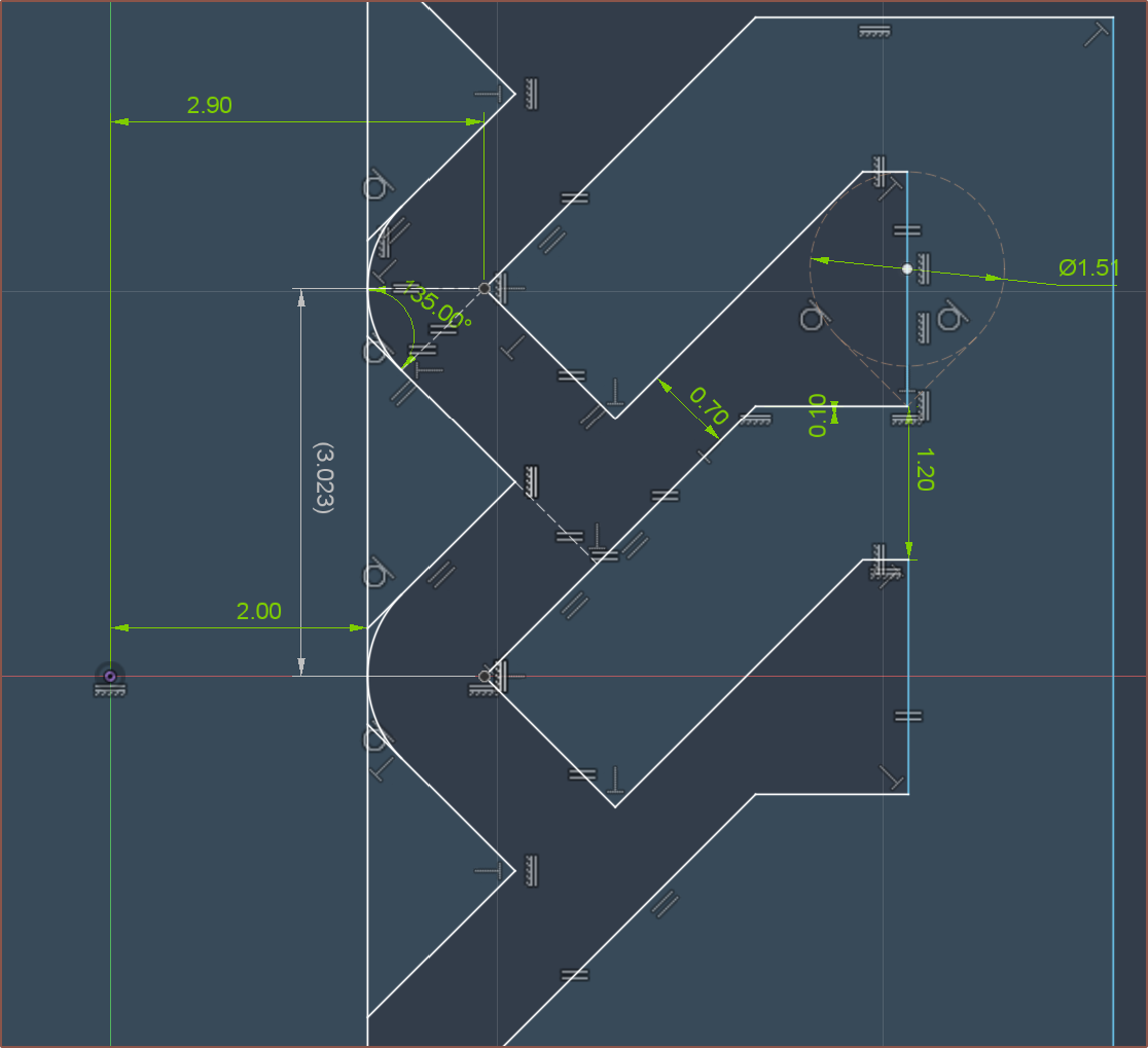
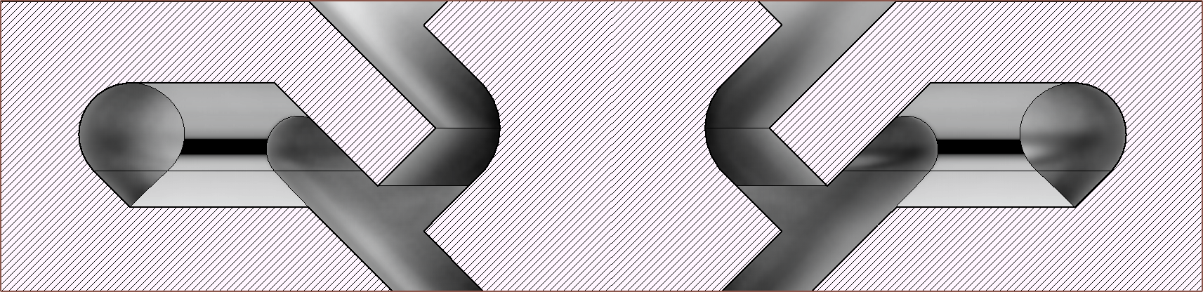
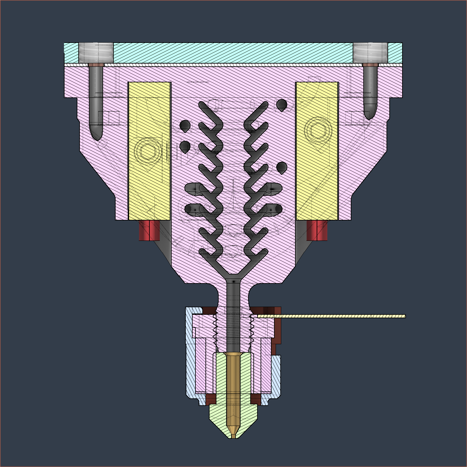
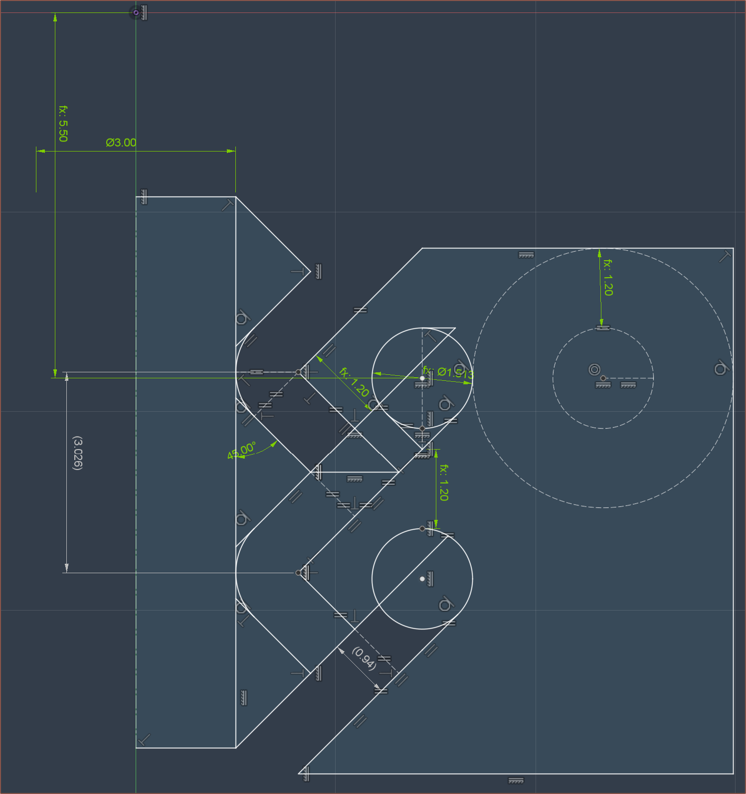
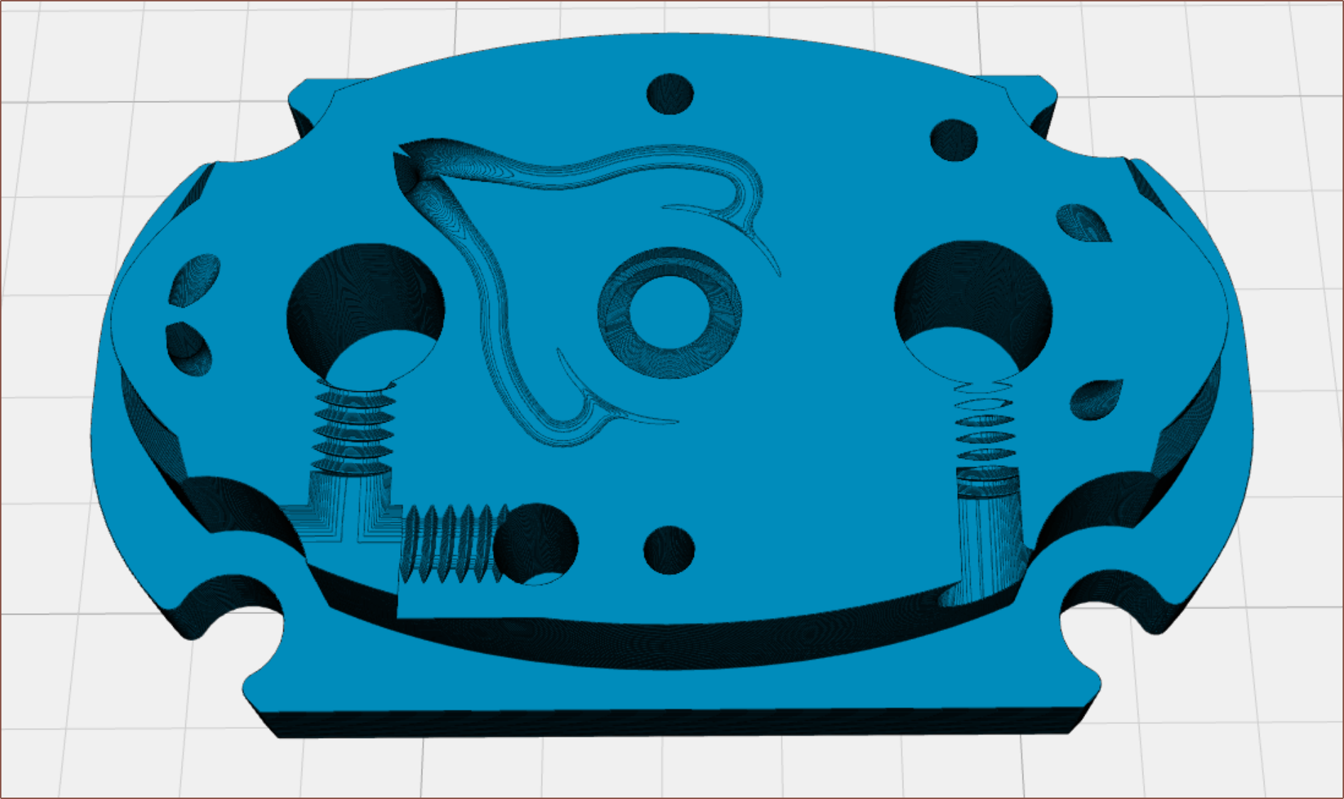
The main profile is shown below:
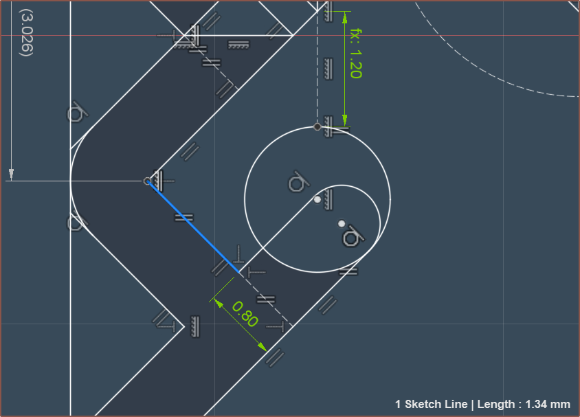
For weeks, I've been wondering if I should change the 0.95mm spacing, but I felt that I didn't want to even change it by more than +/- 0.05mm so I left it. Well now the geometric laws have spoken, and by ensuring a minimum wall thickness of 1.2mm, the spacing is precisely 0.94mm.
Additionally, the centre pillar now has a much more active role in forming the extrudate instead of being there just because I hope it has a positive effect. As the fluid inside the heatblock is incompressible, the idea is that a push/pull of material will move this 3D revolve of the triangle between the 2 inputs:
The volume of this is 9.118mm^3, and the push/pull length can be found as follows:
I had set my push/pull length for the c8or r0 to be 1.8mm, so I'm doing great on these guestimates.
I'm hoping that this new geometry both gives more time for the cone-ring-CSA to equalise in pressure, reduce the diffusion-area between different materials and make the flow interactions more forced.
Pathways
As the aim is to get consistent 360 degree pressure and the crosshead designs I saw yesterday weren't doing any centrifugal-like geometry, I've gone back to a simpler design with 2 inputs. I had considered 3 inputs but feared about pressure propogation delays and how channel 7/8 may have a different pressure profile than the other 6 since I can't just go straight through the heater cartridges. The sketch is shown below:
Well, that's half the reason. I was forced into it because the staggered approach caused minimum-wall-thickness violations.
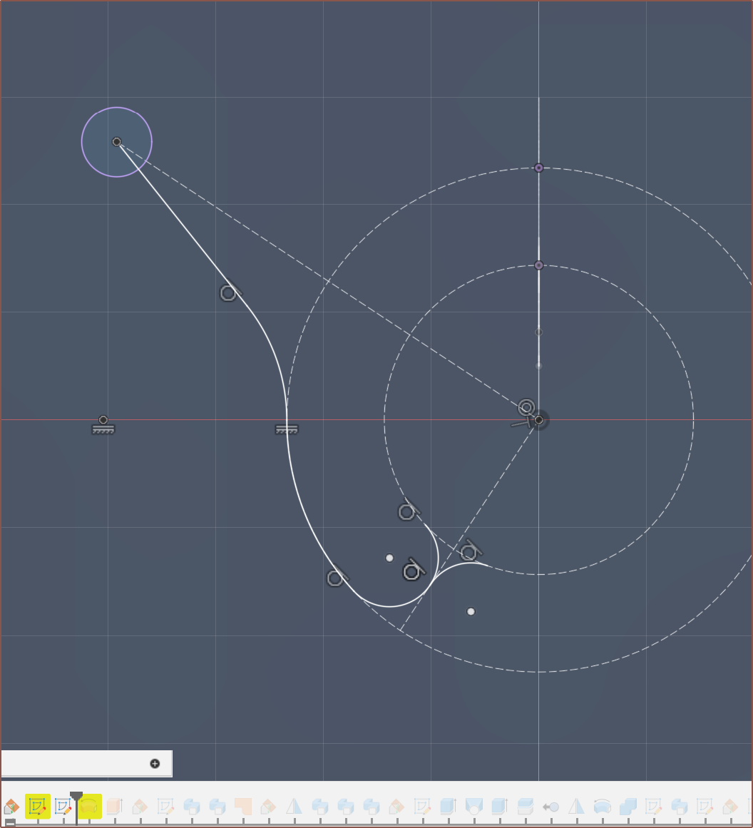
I then tried some conic curves to transition from the minor to major channel, mainly so that channel4 was more spaced from the paths of channel7.
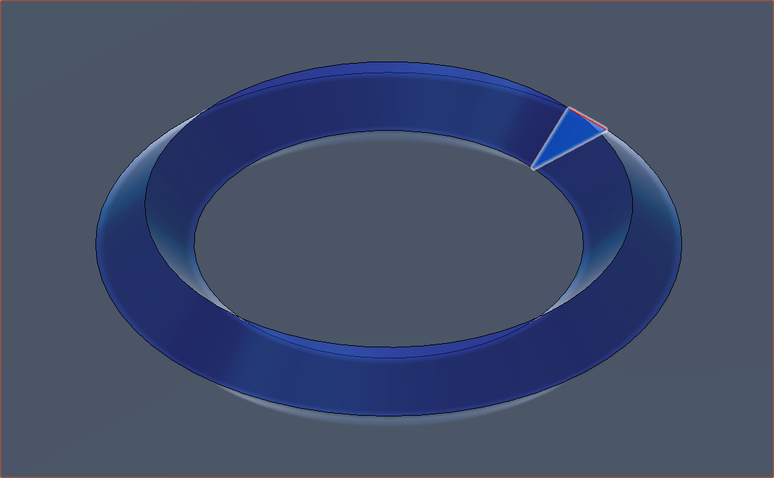
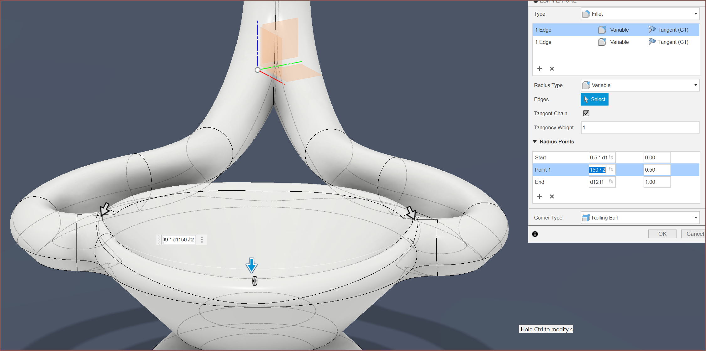
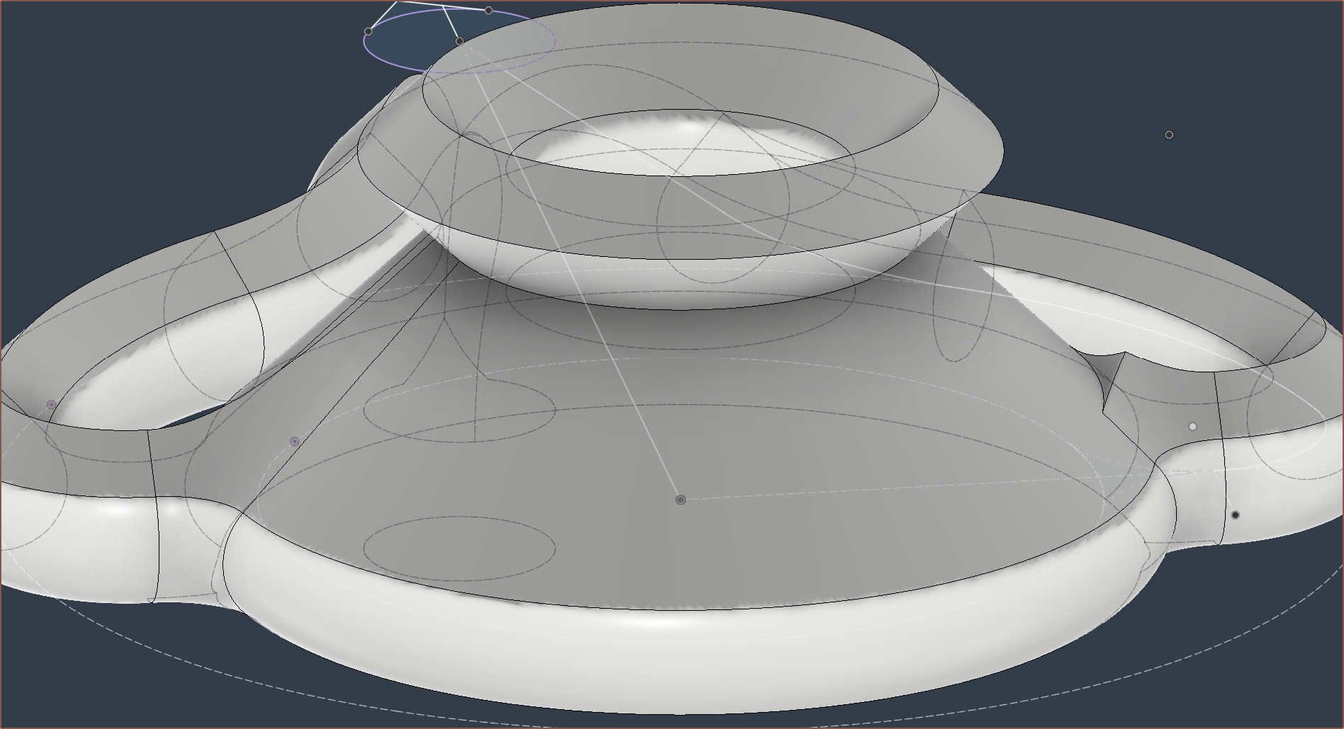
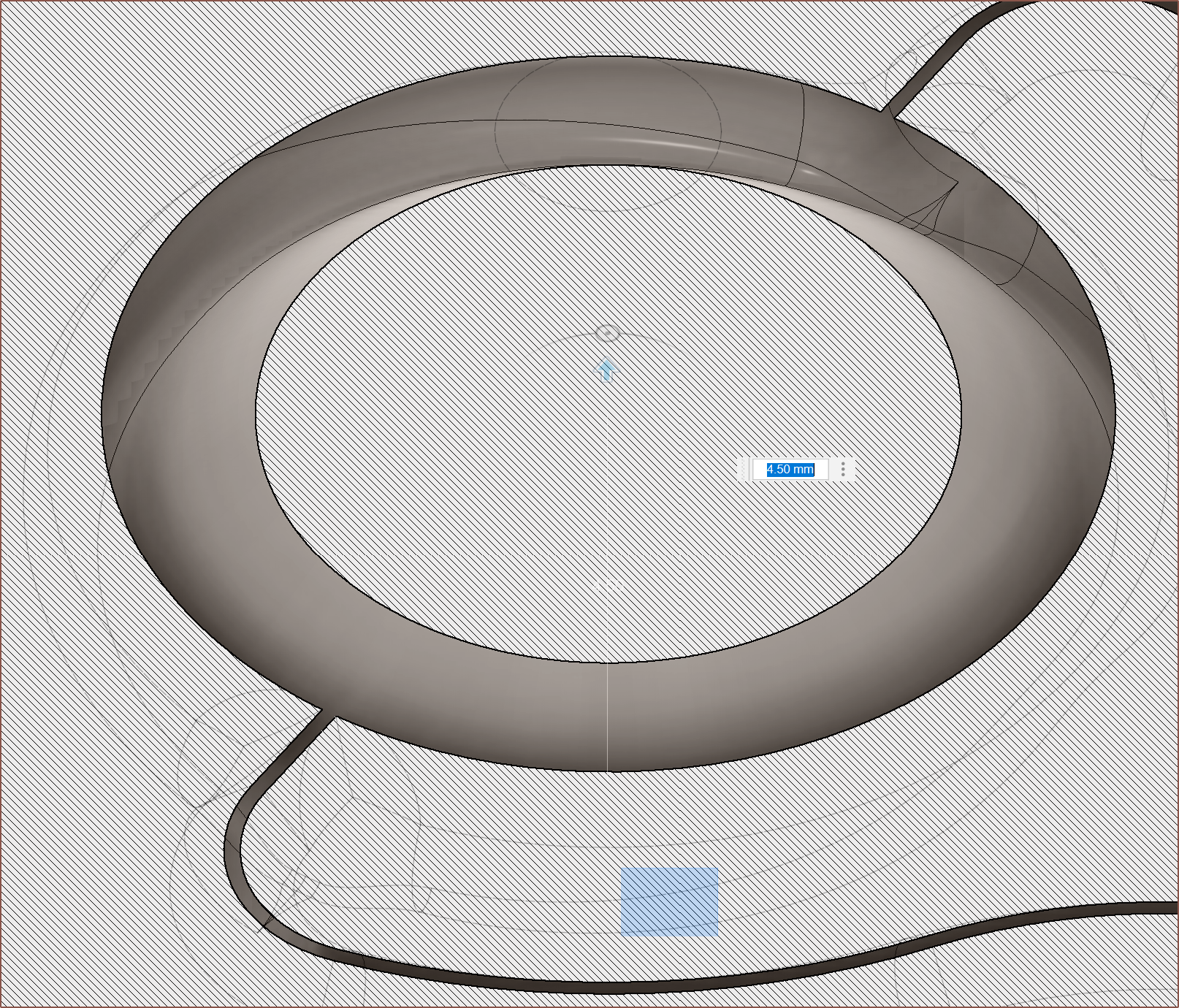
I did the revolve and then made this fancy variable fillet which aims to keep the pressure more constant as material moves further away from the inputs:
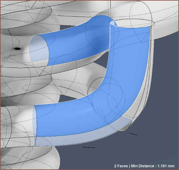
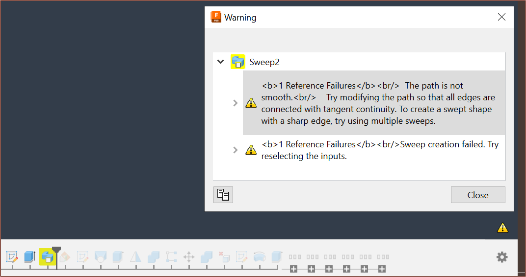
About 2 more hours of fixing later (which didn't help since Fusion decided to delete some features and sketches instead of just making them yellow or red) and I had the new geometry implemented. Almost everywhere was >=1.2mm minimum wall from what I could tell.
I decided to let this one slide, at 1.181mm distance.
The heatbreaks go right to the edges of the bounding box, but I was still able to keep the 29 x 49 XY size.
Next-day fixes
First I tried something called draft analysis as I was hoping that I could use it to see overhangs over 45 degrees, but it seems limited in that it's only optimised for injection-moulding workflows and, as such, I can't set anything over 15 degrees.
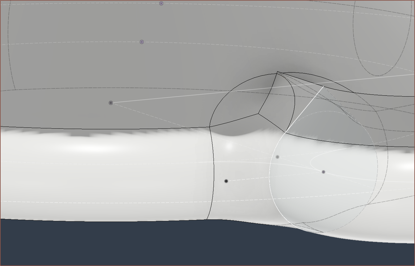
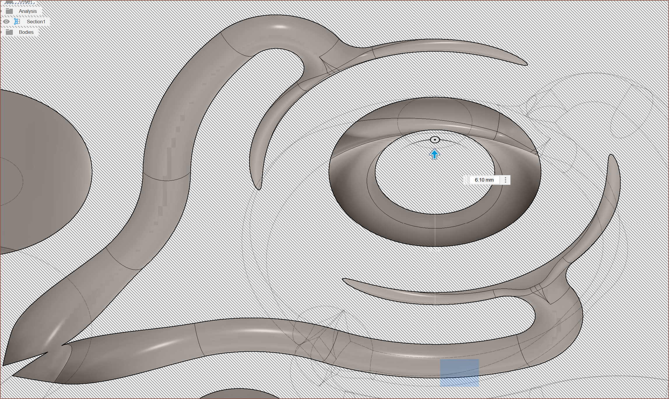
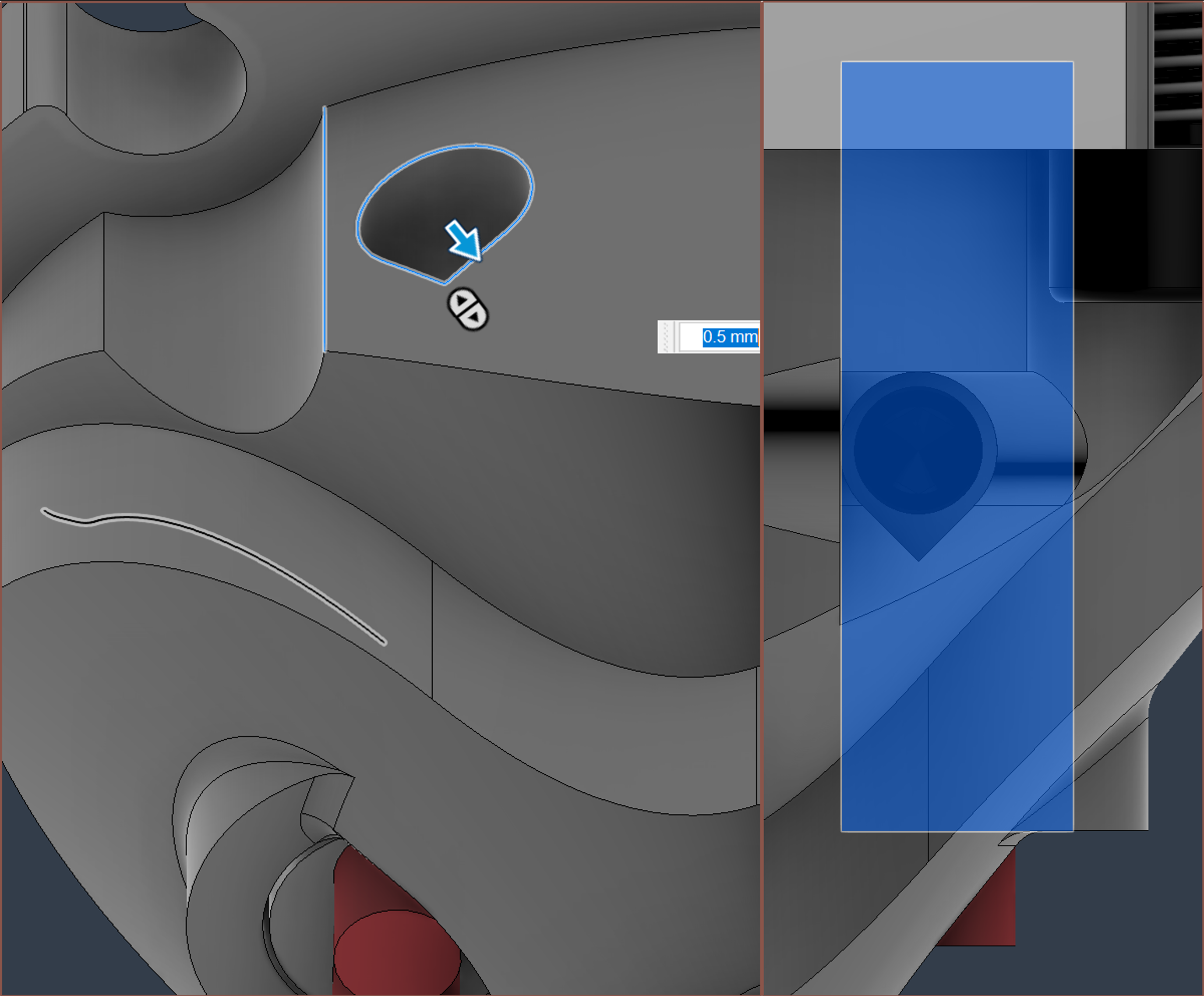
So I did the usual cross section analysis and found this issue of floating material:
Fixing it was not straightforward, and I was getting geometry like this:
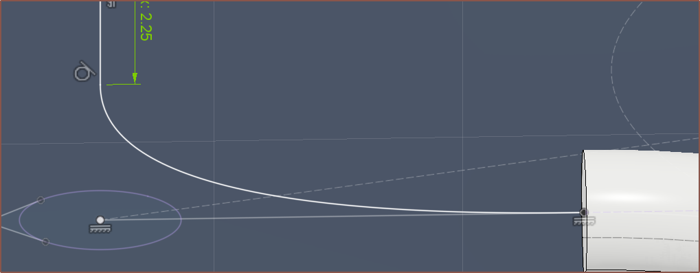
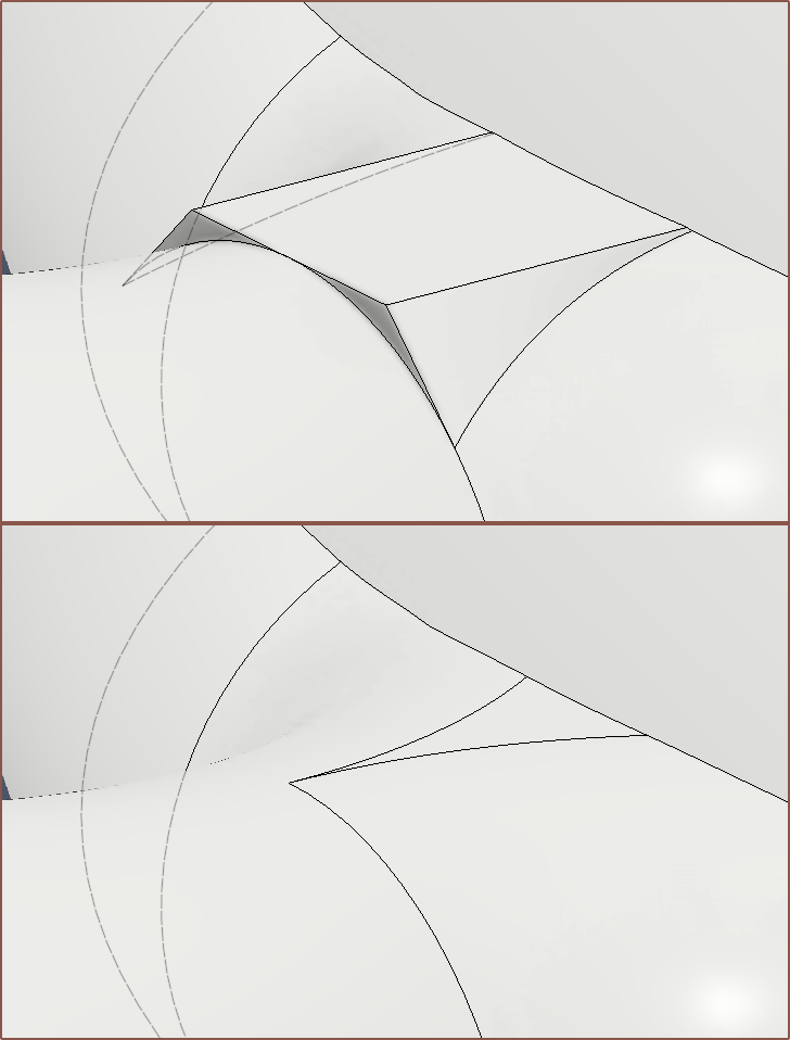
The solution was to remove the triangle on the left/right path profiles, and have a straight extrude, and then fillet the result:
I was having issues with the fillet because the underside was bumpy, so I flattened it out with some Delete Faces magic:
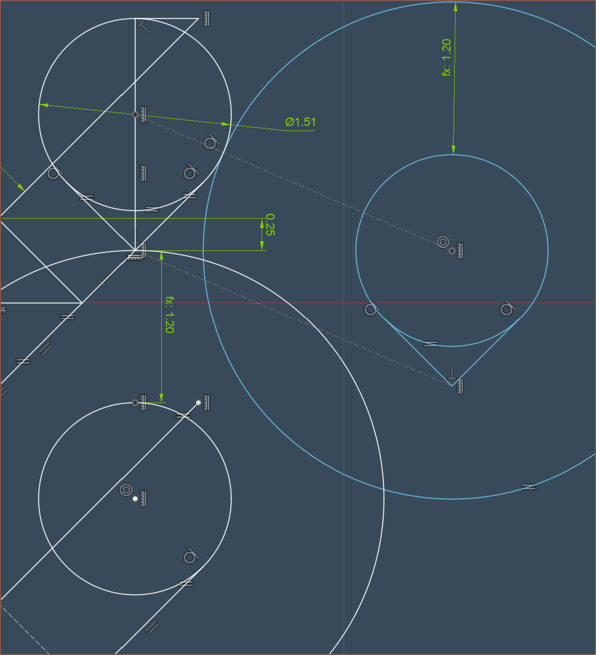
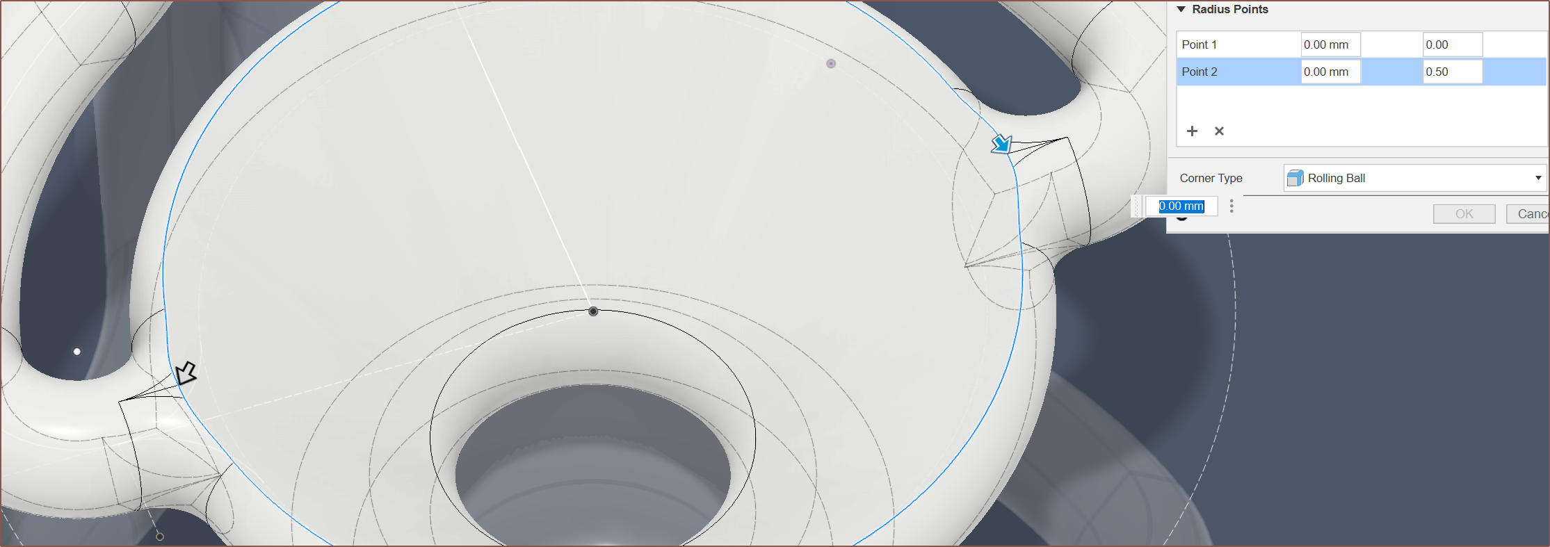
Lastly, I split the faces so that the variable fillet had nice points of 0.0, 0.25, 0.5, 0.75:
Throw in a few unexpected erros that resolved themselves when dimensions were tweaked by 0.1mm...
... and I got a satisfactory result that didn't violate minimum wall thickness, as seen below.
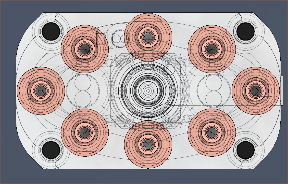
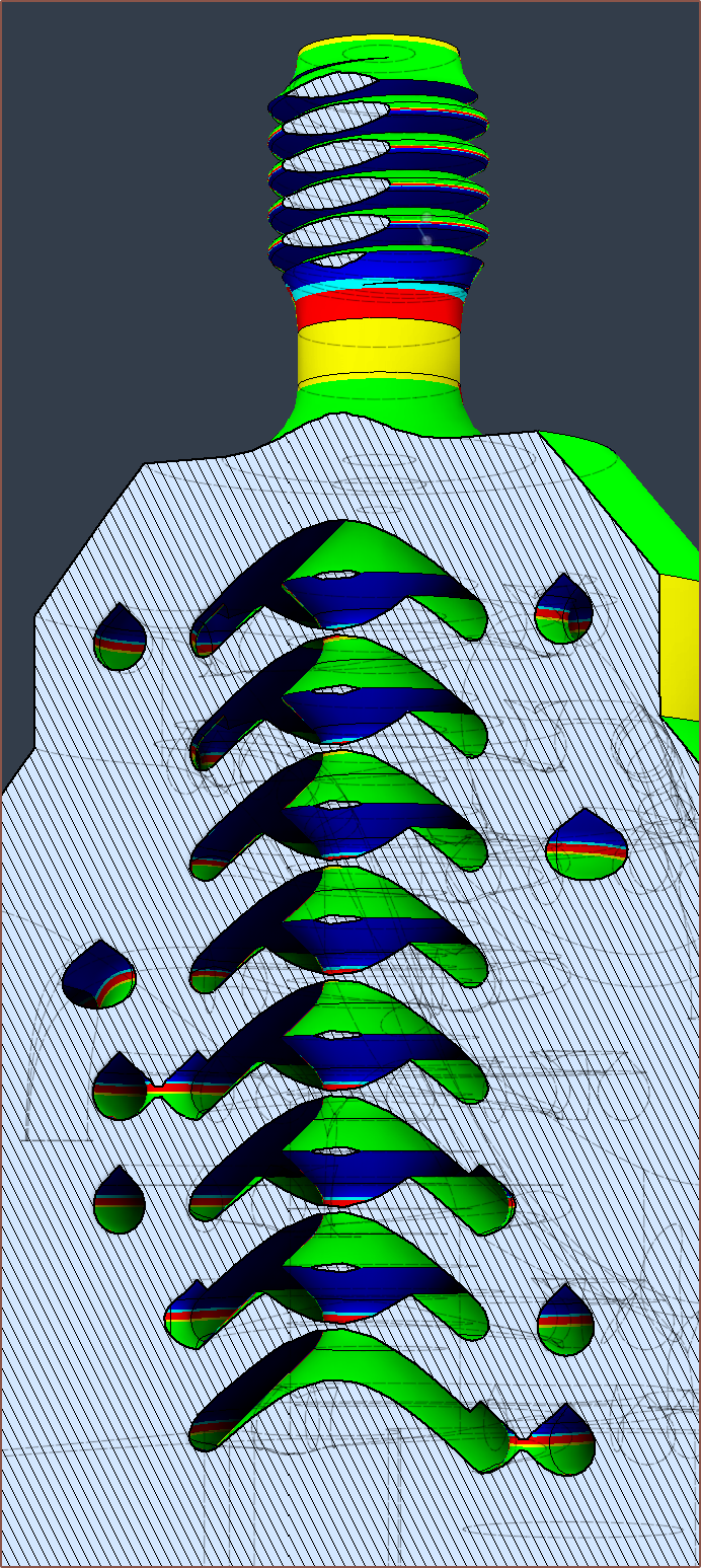
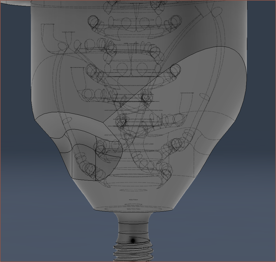
Analysis and quotation
So I did a more thorough cross section search this time, using both Fusion and Kiri:Moto. I took the exported .step and added in modelled M4 threads to represent what would happen after post processing.
Notice how, due to the variable fillet, the input section varies in Z height.
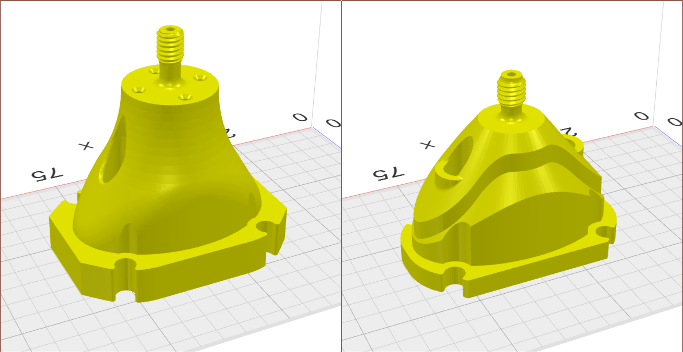
Just look at that difference between R0 and the current R1 design:
It looks like the difference between a family car and a sports car.
The cross sections all looked like there was ample distance between walls (which I'd then confirm in Fusion):
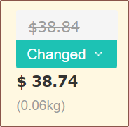
I've sent in a quote and I'm currently waiting to hear back from the engineer before I press buy this time, but I've already gotten the pricing quote back:
Yes! You see that, right? $38.74. For the first time ever, the actual quote is less than the auto-quote! Yes it's 10 cents, but this is amazing how I've essentially gotten the price down to PCBWay's single-quantity minimum of around 37-39 USD. I will mention though that Heinz has found that for a much smaller part, one can get 1pc for the same as 5pcs, thus $6/ea.
[20:20]
By quickly scrolling between the layers in Kiri:Moto, I was able to see that I could easily eliminate the slight minimum-wall violation I mentioned earlier (1.181 < 1.2) by just swapping the input locations of Ch5/6. This results in being able to use a normal arc instead of a conic curve, simplifying the sketch calculation for the Ch7/8 outer trim and resulting in a 0.5g reduction in total mass (the volume is now 191cm^3).
If you're wondering why I keep mentioning the total volume when the mass differences are negligible, it's because I'm having fun beating personal best, similar in principle to Trackmania where I feel 0.4 seconds improvements are solid gains.
[21:50]
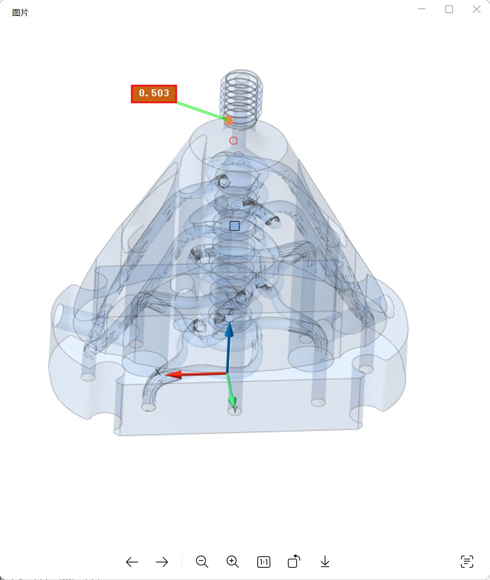
I noticed that one small fillet didn't look correct. I went to investigate and yes it was an actual issue:
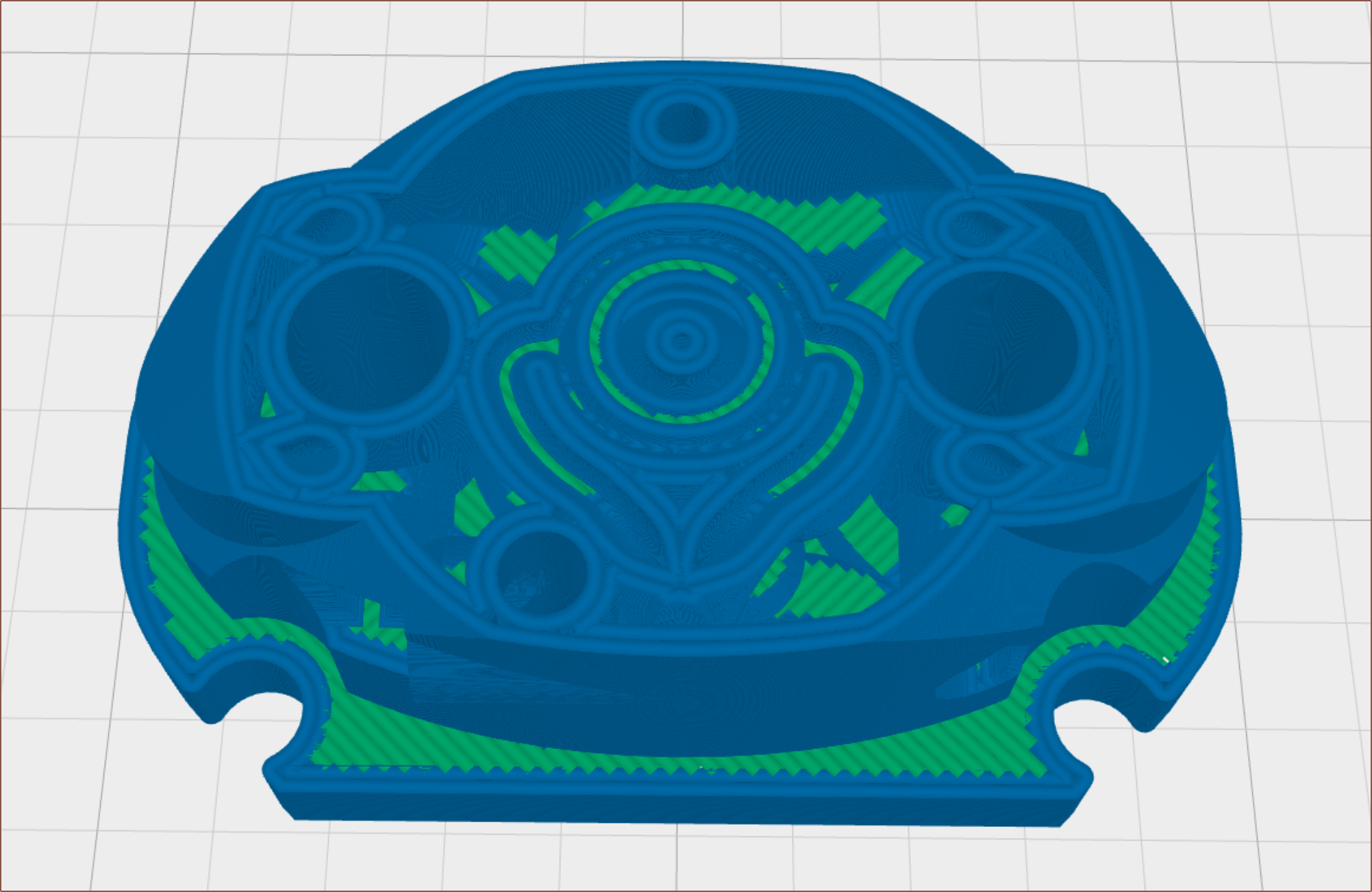
Turns out that the thermistor sketch broke a bit and was corrected. I've now gone into the FDM mode of Kiri:Moto to confirm that minimum wall thickness, at least in the XY-Plane, is ensured. I've used a 0.6mm nozzle size, which means that all walls should have at least 2 lines of thickness.
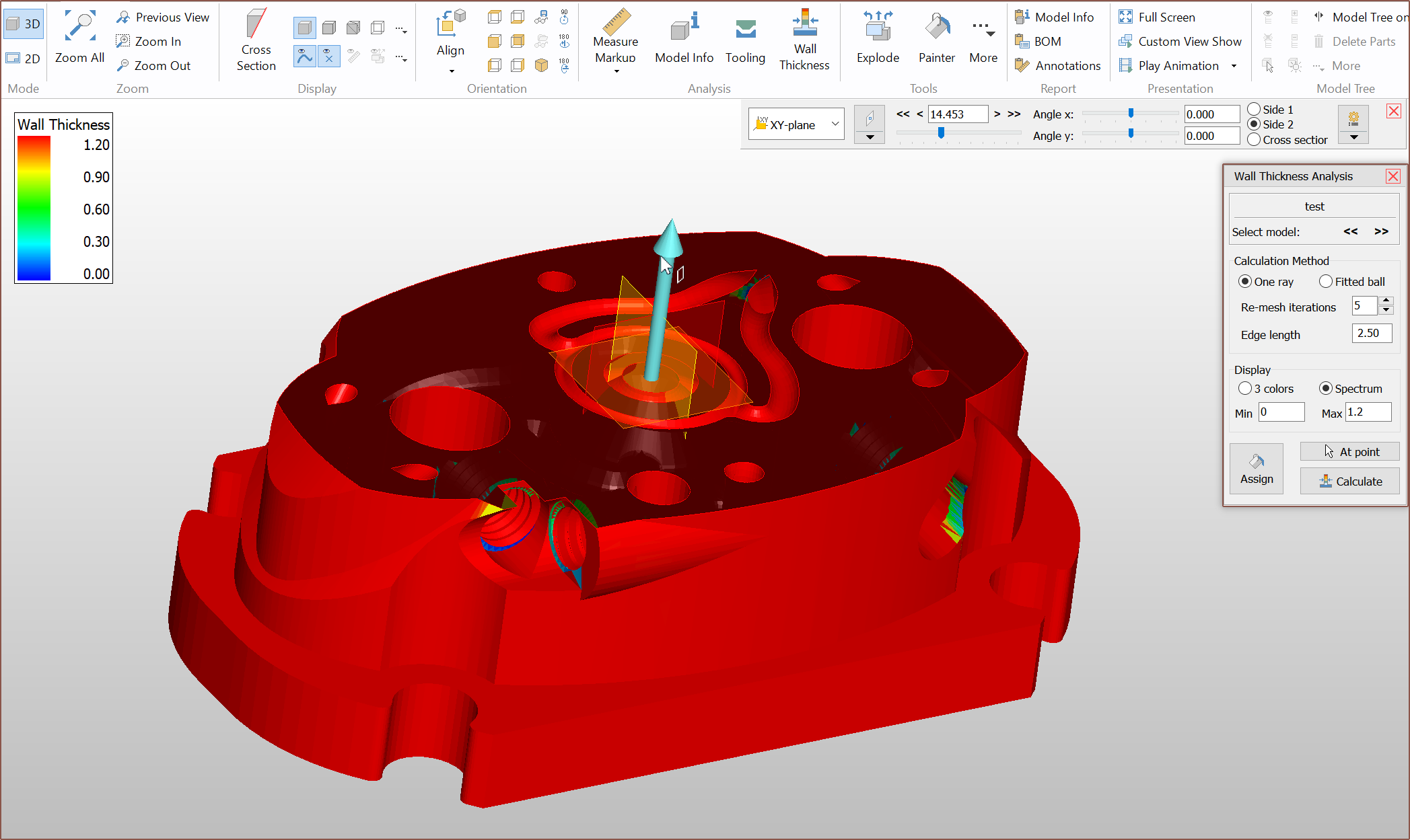
This still wasn't all that ideal, and so I set off to find a way to get a wall thickness analysis tool and found the free 3D-Tool viewer which can take in a .3mf and I can get both analyses for cross section and minimum wall!
It also uses the same view navigation mouse keybinds as Kiri:Moto.
[Apr 13]
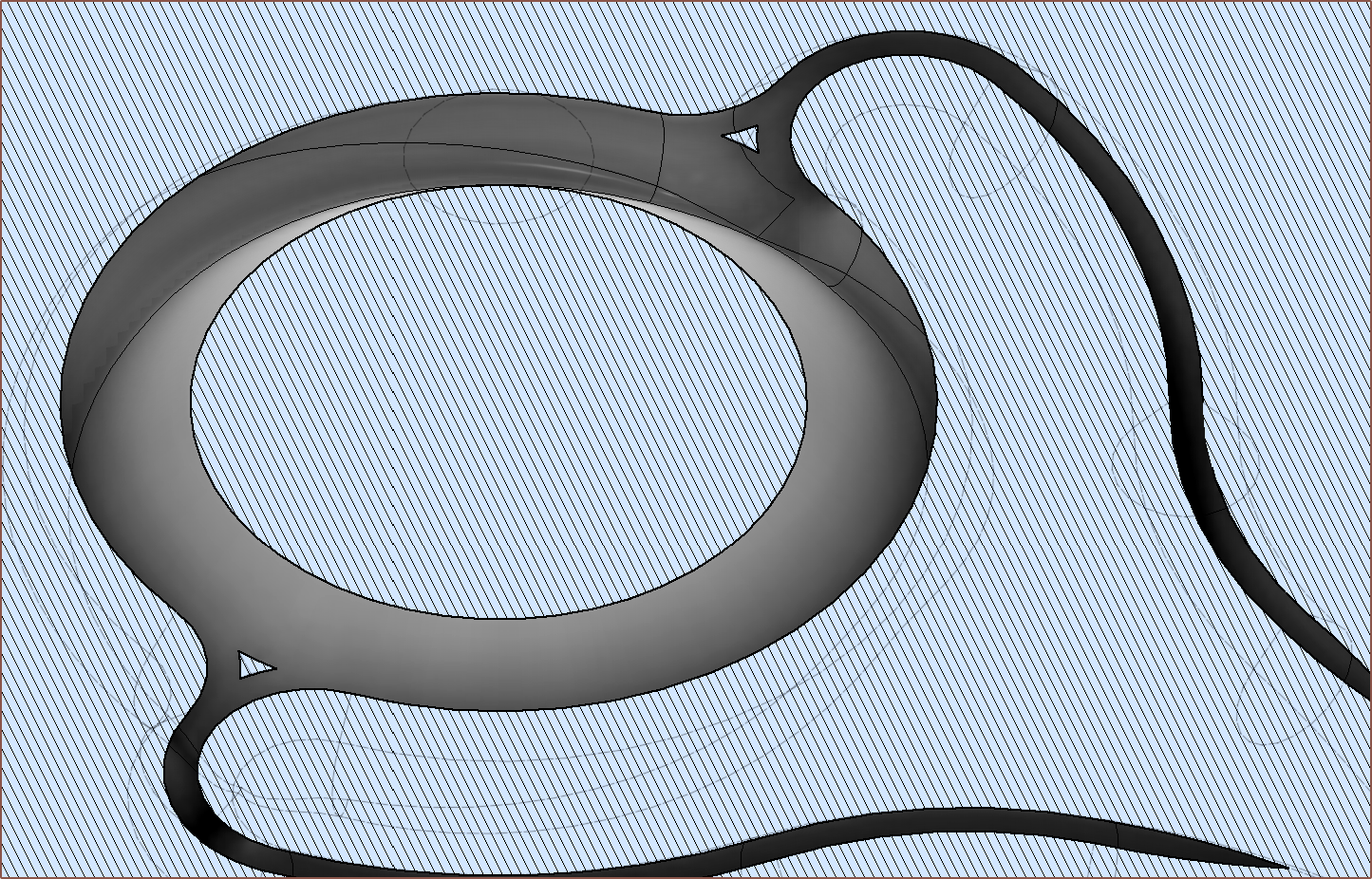
I've combed though and I think all the issues with the CAD has finally evaporated off. I've removed the minimum wall violation where the grub screw was, and I've added some nice 6mm fillets that was mainly to try and address the furthermost grub hole but I believe is just what the design needed for this nice, flowy look.
The conical outer design is a bit like if you take a 3D topology map and form it around a cone instead of a plane.I think it's ovur... but the good kind. 19011mm^3
Hopefully, this design is manufacturable. I have the confidence that, as long as the price is close to the autoquote, I'm getting 2pcs so that it's not instantly "game over" if Team Leak get's a 3-0 in this battle. I believe that the design is good enough that I would need concrete performance metrics before I tweak and change anything else.
[Apr 14]
I've realised that it's actually possible to set an internal coaxial spacing lower than 0.94, whcih will actually thicken the walls.
A reduction from 0.94 to 0.80mm (15%) decreases the hypothetical purge volume by about 30%. Remember though that this is all just raw-CAD numbers and the spacings between the walls are expected to be lower in manufacture. The worry is lower flow rates. I know 0.95mm spacing works so I'm just going to stick with the 0.94mm modelled.
I've cancelled the PCBWay order for the Coaxial8or R1.
It started small. Small as in a small missing fillet. That was easy to correct.
Then the engineer came back because they had concerns about the M6 threads:
I looked at how Heinz did their threads and one thing I noticed was the taper before the flat wasn't a basic chamfer. I presume this is so that imperfections from the printed thread does not affect the important face that seals against the nozzle.
Thus I went in and did some modifications:
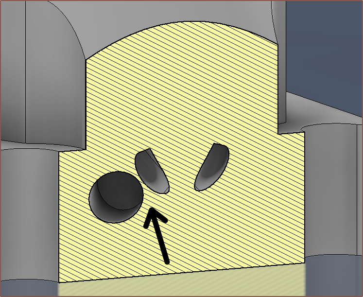
Then I was validating the model and found an extreme minimum wall violation that I unfortunately missed:
The hole is the grub-screw hole and so I had to rethink quite a bit of the design (and this is when I requested the order be cancelled since it could take a while).
Fast forwarding a bit, I moved the grub screws, reduced the clamp block thickness because it no longer had to fit the grub screws, and trimed the body of the heatblock so that I could simultaneously get under 20,000mm3 and $40 autoquote, and I got this:
Side tangent: Trimming around channel 7 / 8
I first tried doing the trim with an extrude and draft angle but it just looked... wrong... so I instead created a cone surface and extruded to that, which actually trimmed off even more material.
Tangent over. Back to the main story of events.
So I was dancing about how my design is now 193cm3 and the autoquote was $38.80, and I was on Discord asking Heinz a few questions to get the latest insights in the technology tree. The response:
-- lots of colors are nice, but biggest improvement is in the coating meachanism itself imho.
-- making it as small as possible for less purge and quick color change
--
similiar to the cetus2 brass insert...
I was going to reply that I felt like colour gamut vs colour change speed would be one of those engineering challenges where one is forced to pick a side. I still feel that way, but that it's not as black and white as I originally thought.
Remember that print of a clip that was supposed to be white but only got to a medium-light grey at best?
Well I looked into the model cross section and determined that I needed to reduce the contact zone between differing materials whilst still being manufacturable.
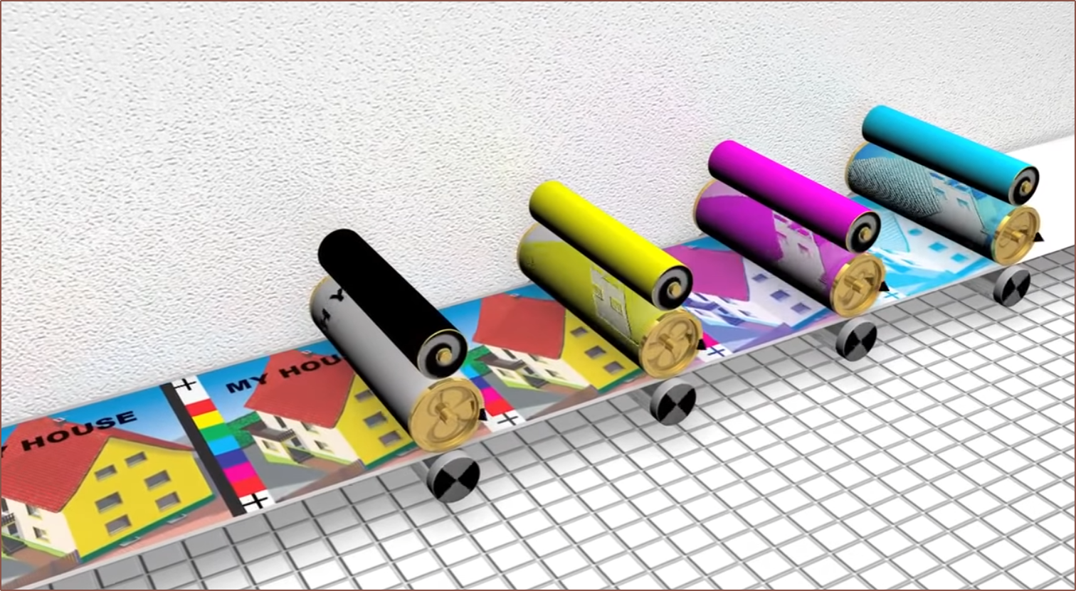
Ideally, colour changes inside the melt chamber would be like a Pallete filament splicer, but with molten filament. Another way to think of it is like a 1-dimensional version of offset printing where each colour is separated by some finite distance and the change in colour is a single point on the length of the pipeline:
The final colour output created by merging the combined-effort of previous work with a single colour.
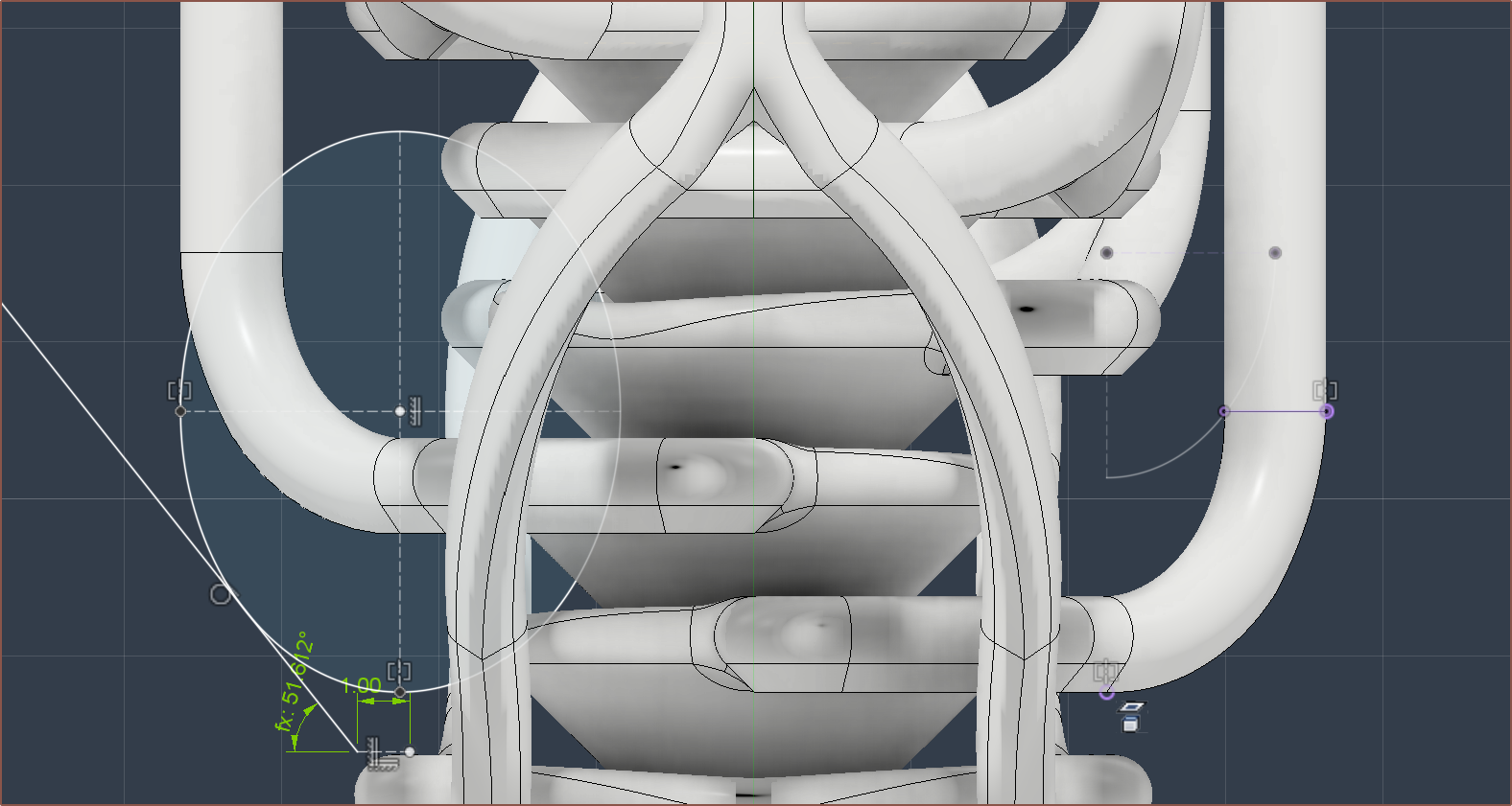
I started sketching a solution that could potentially be geometrically viable yesterday:
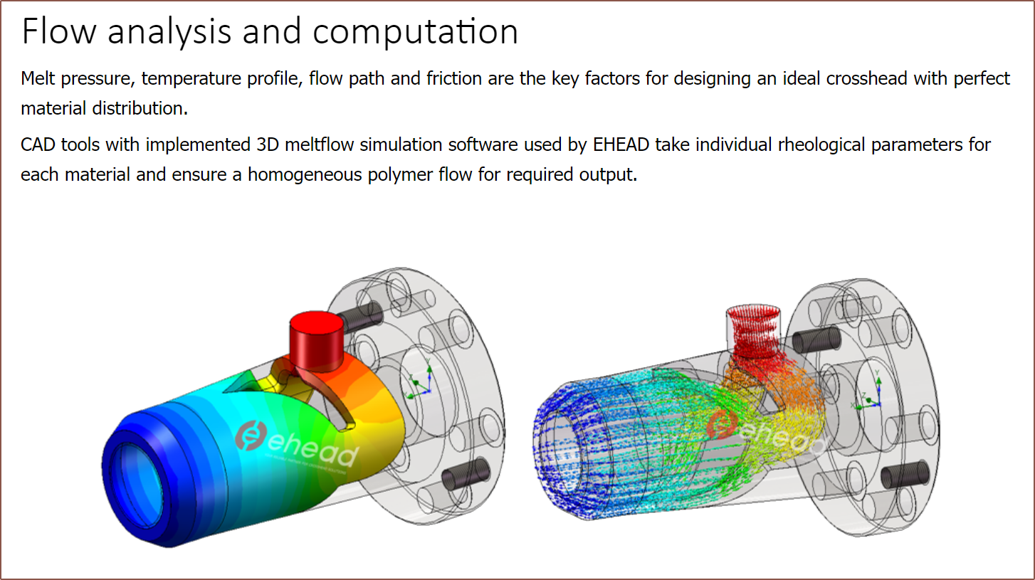
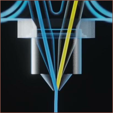
Today, I've looked into "Crosshead Extrusion", which is a method to coat wires with insulation:
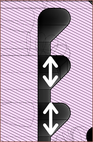
I'm continuing to experiment with what I can do with the design whilst keeping it compact, ensuring a minimum wall thickness and keeping the pressure as axissymmetric as possible:
The idea is to make the geometry more like a revolved version of the Cetus2 nozzle for each channel. This is also to hopefully make push/pull vtools more effective.
Cetus2 nozzle. If you changed the angles so that the two inputs are perpendicular and then revolve it around the left or right edge of the image, the result is similar to what I've started to come up with.
Perhaps it's because this design is similar to R0 which PCBway already has experience on, but now the autoquote and the actual price were essentially identical. Unexpectedly, the "Standard Global Shipping" is now almost half the cost. Perhaps it has something to do with the bounding box of R1 being smaller than 50 x 30 x 50mm3?
Another possible reason for the lower price could be that the 1.5mm channels are easier to clean inside than the 1.25mm ones?
The current Mastercard conversion rate means that it will cost me £45.25.
Simulation attempts
I was going to install the Windows Subsystem for Linux to try OpenFOAM, but then I found out and tried to use the injection moulding simulation feature in Fusion 360. Unfortunately, it complains if I set the mould temperature to something like 236C for PETG, and when I set it to within the recommended values, I got an incomplete fill animation:
I can use my imagination for this much of a simulation.
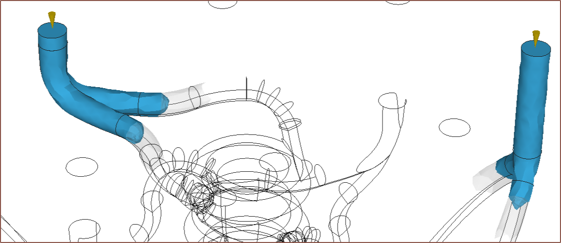
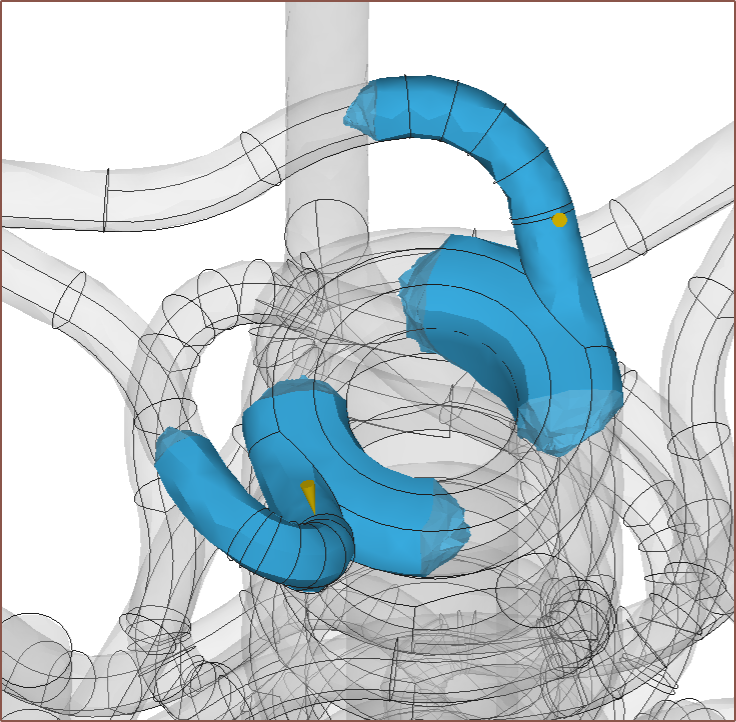
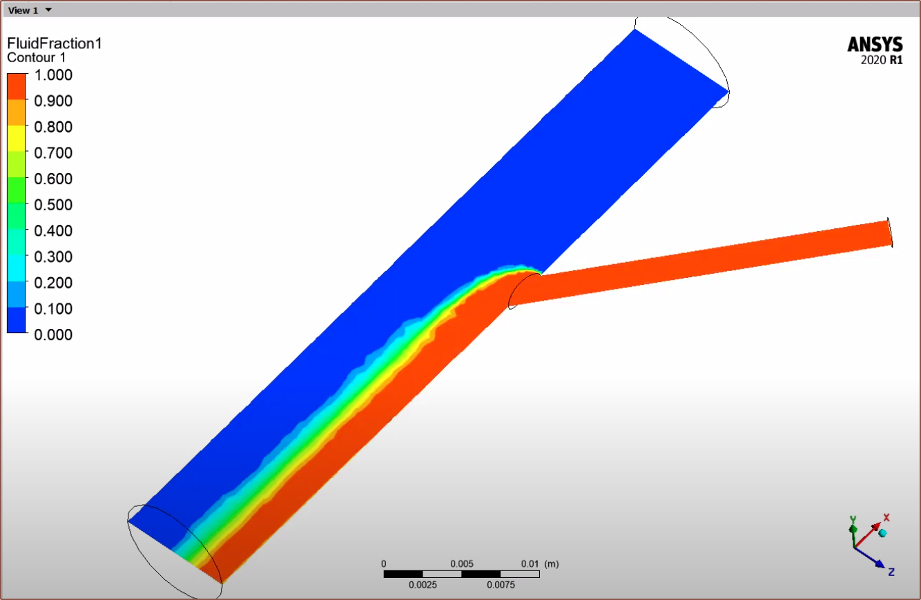
[Apr 07] There was a material called "Bionolle" that had a close melt and mould temperature of 115C and 80C respectively, and I moved the inputs so that I could at least see the filling of the coaxialiser and path length matching.
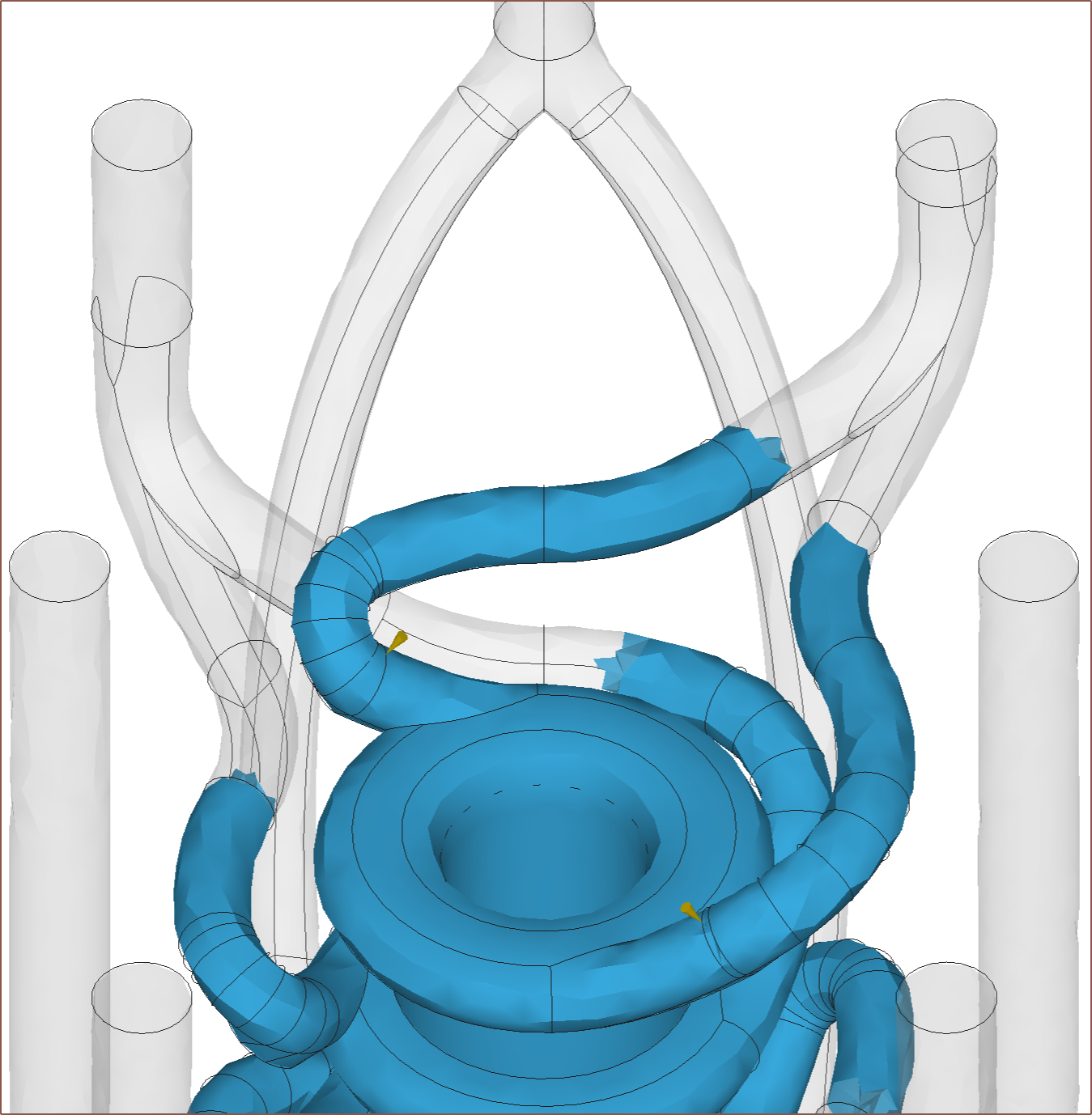
Allegedly, the material will expand into the empty space from both directions instead of only clockwise.It seems that the paths for all 8 inputs are matched to within about 1.5mm. Hopefully, this means that the pressure difference between the splitting paths is low.
[End of Apr 06 edit]
I signed up for SimScale but it became apparent very quickly that I'd only be able to simulate liquids like water and oil.
Ideally, it seems that I'd need something like Ansys Polyflow, which seems to be able to simulate coextrusion:
 kelvinA
 Thus, I was wondering if the dust needed to be agitated. "Hm, what I need is maybe like an ultrasonic cleaner or something. Are any of these machines [around me] one?", I thought.
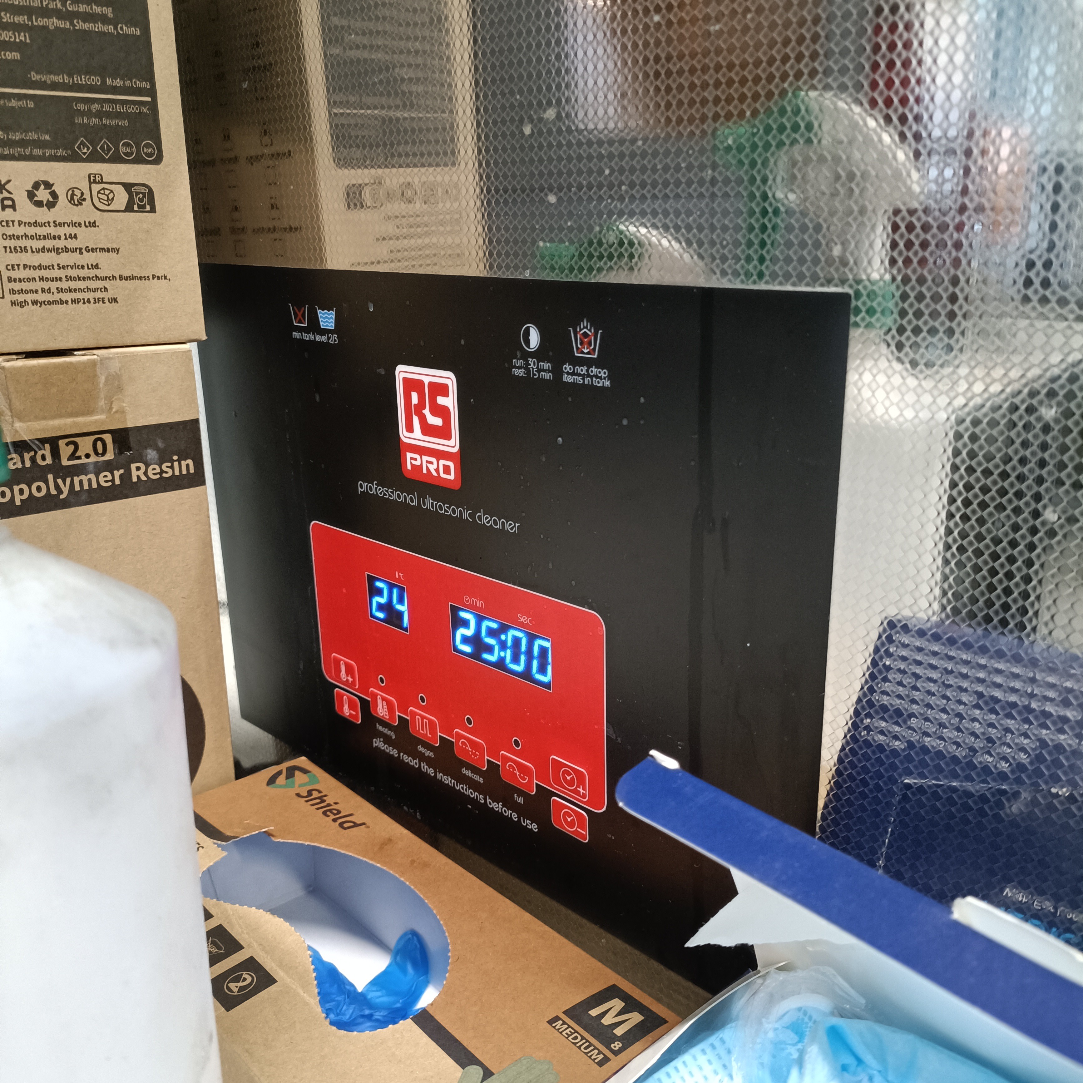
 Yes, I retrieved and cleaned up the clamp plate from Coaxial8or r0. I pried off the plastic and cartridges from the clamp plate, then put it in the above tub along with a shallow amount of kettle water so that the PETG softened and I could clean off the rest.
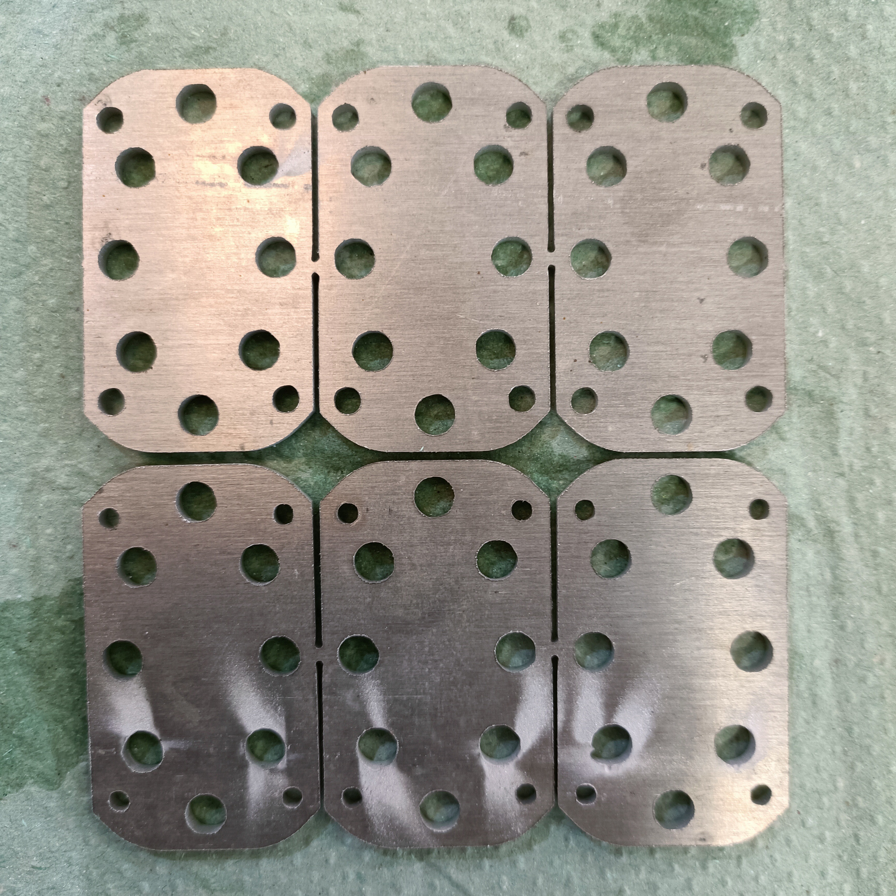


 A reduction from 0.94 to 0.80mm (15%) decreases the hypothetical purge volume by about 30%. Remember though that this is all just raw-CAD numbers and the spacings between the walls are expected to be lower in manufacture. The worry is lower flow rates. I know 0.95mm spacing works so I'm just going to stick with the 0.94mm modelled.
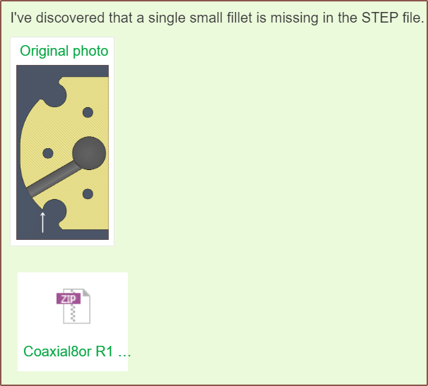
 I first tried doing the trim with an extrude and draft angle but it just looked... wrong... so I instead created a cone surface and extruded to that, which actually trimmed off even more material.