Fabian
Since I have been working with the (here in Germany) successful "balcony power plants", I have been wondering how the energy yield of the two to four solar panels can be further improved.
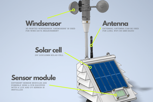
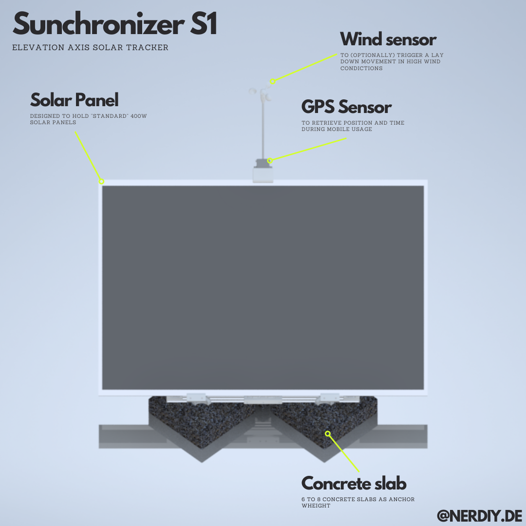
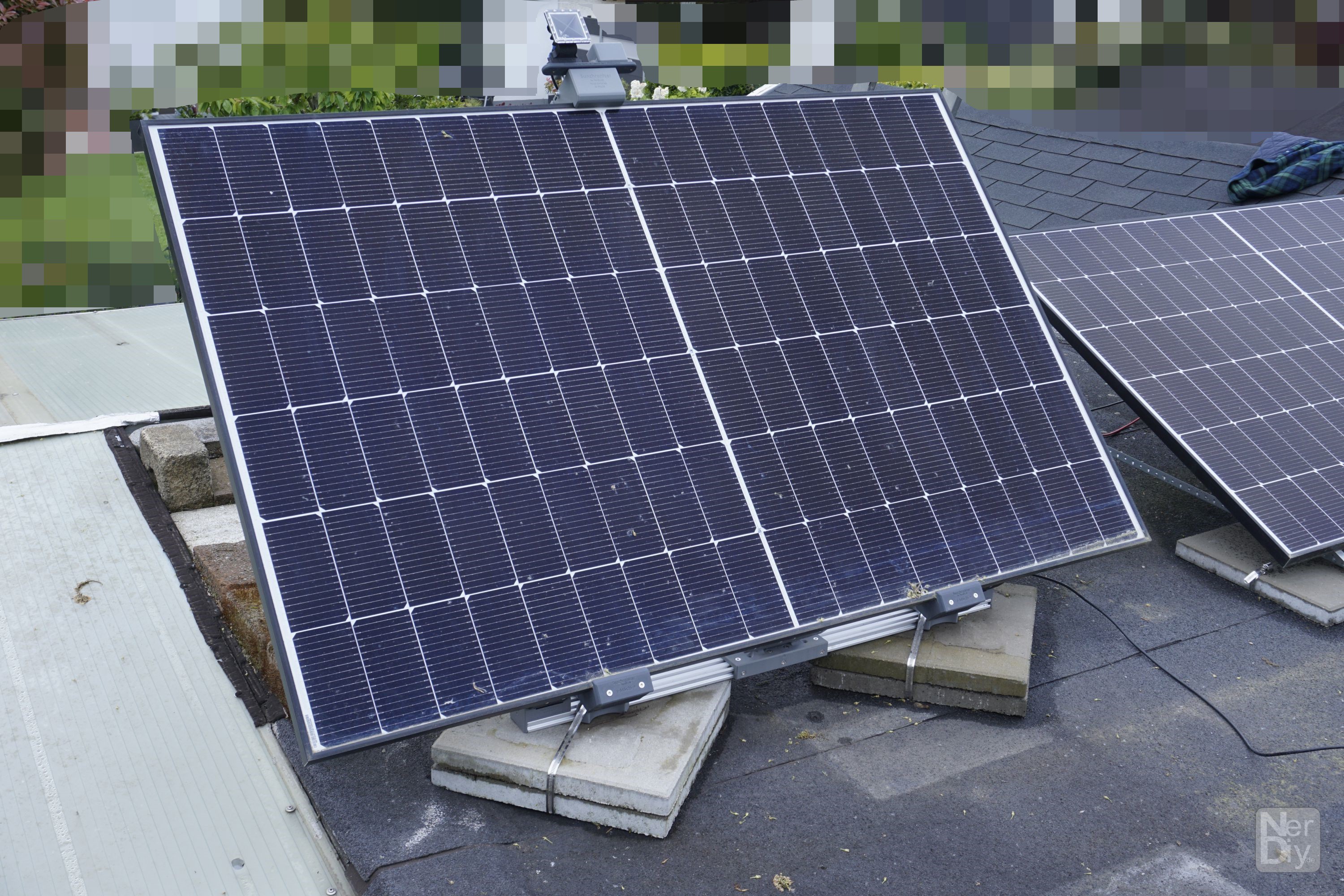
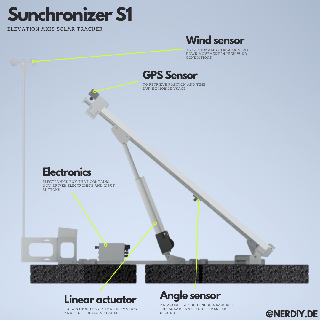
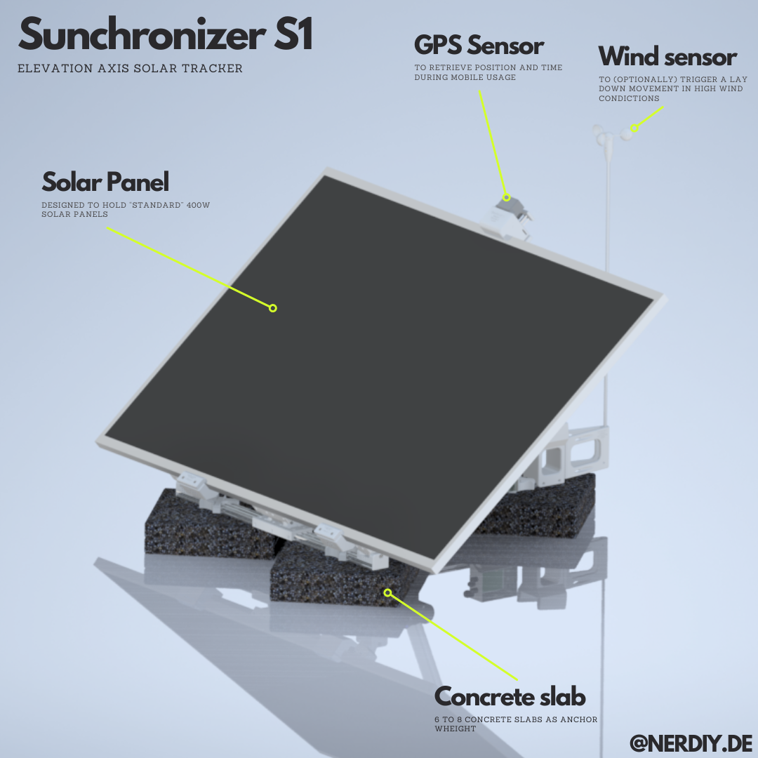
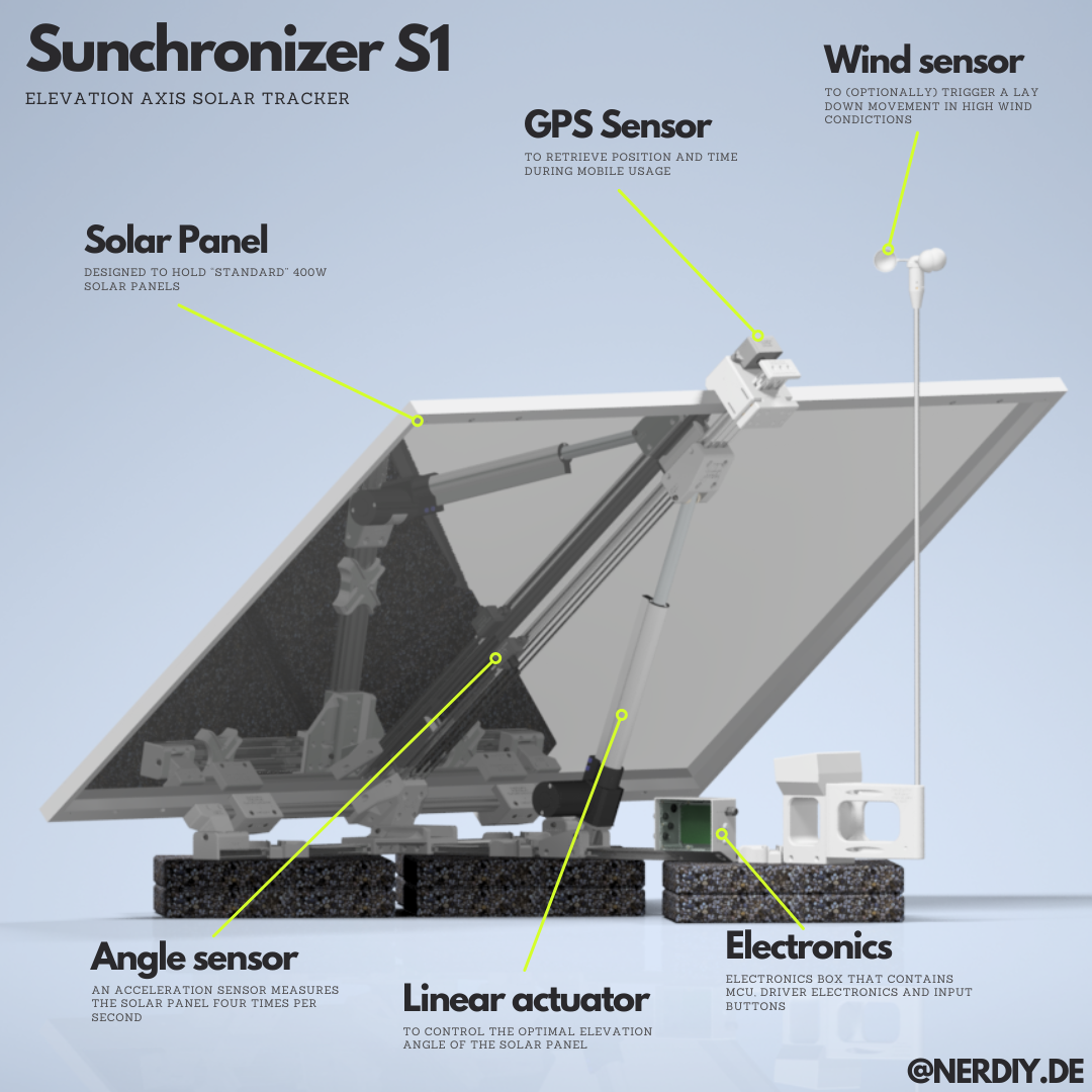
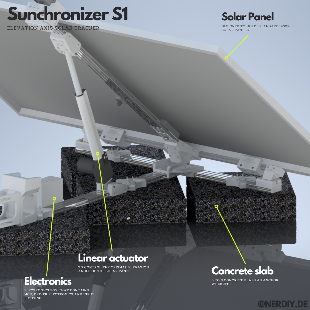
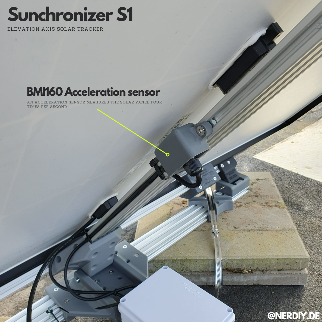
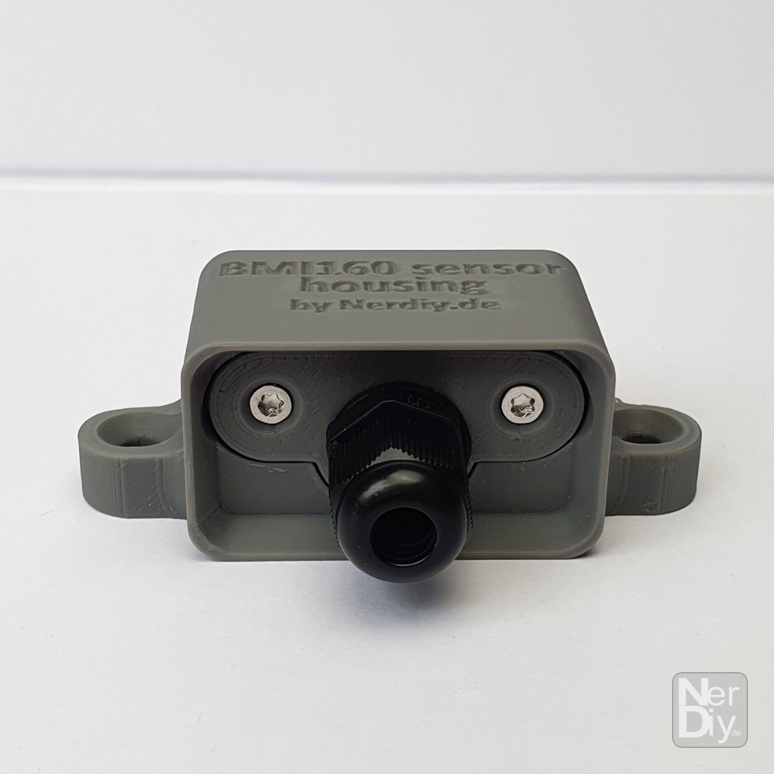
The Sunchronizer S1 is my first design of a a solar panel mount for "standard" 400" solar panels that automatically tracks the sun on one axis. As with my past projects, I tried to rely largely on 3D printed components and standard mechanical parts. Ultimately, with this everyone should be able to build a solar tracker for their solar panels themselves.
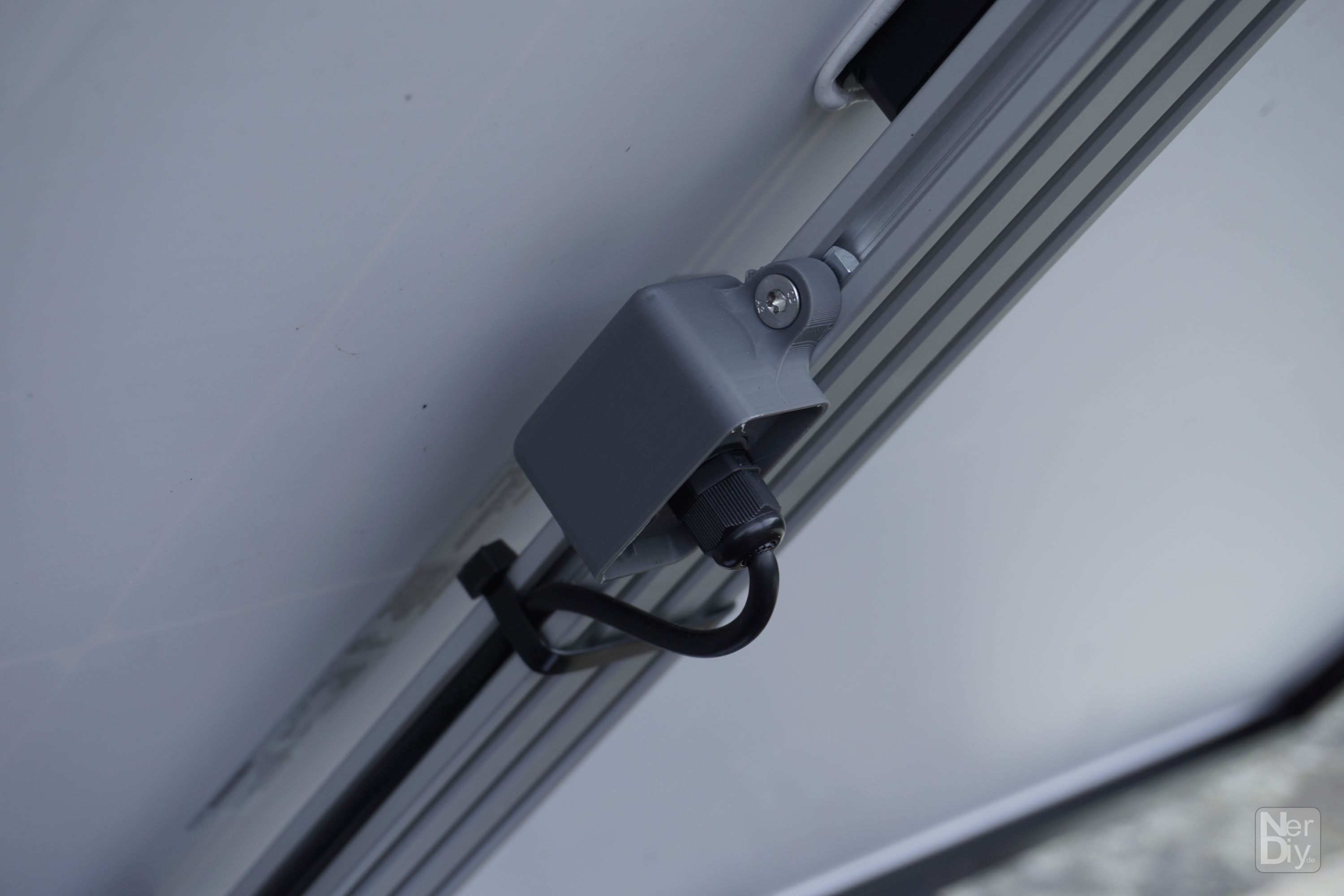
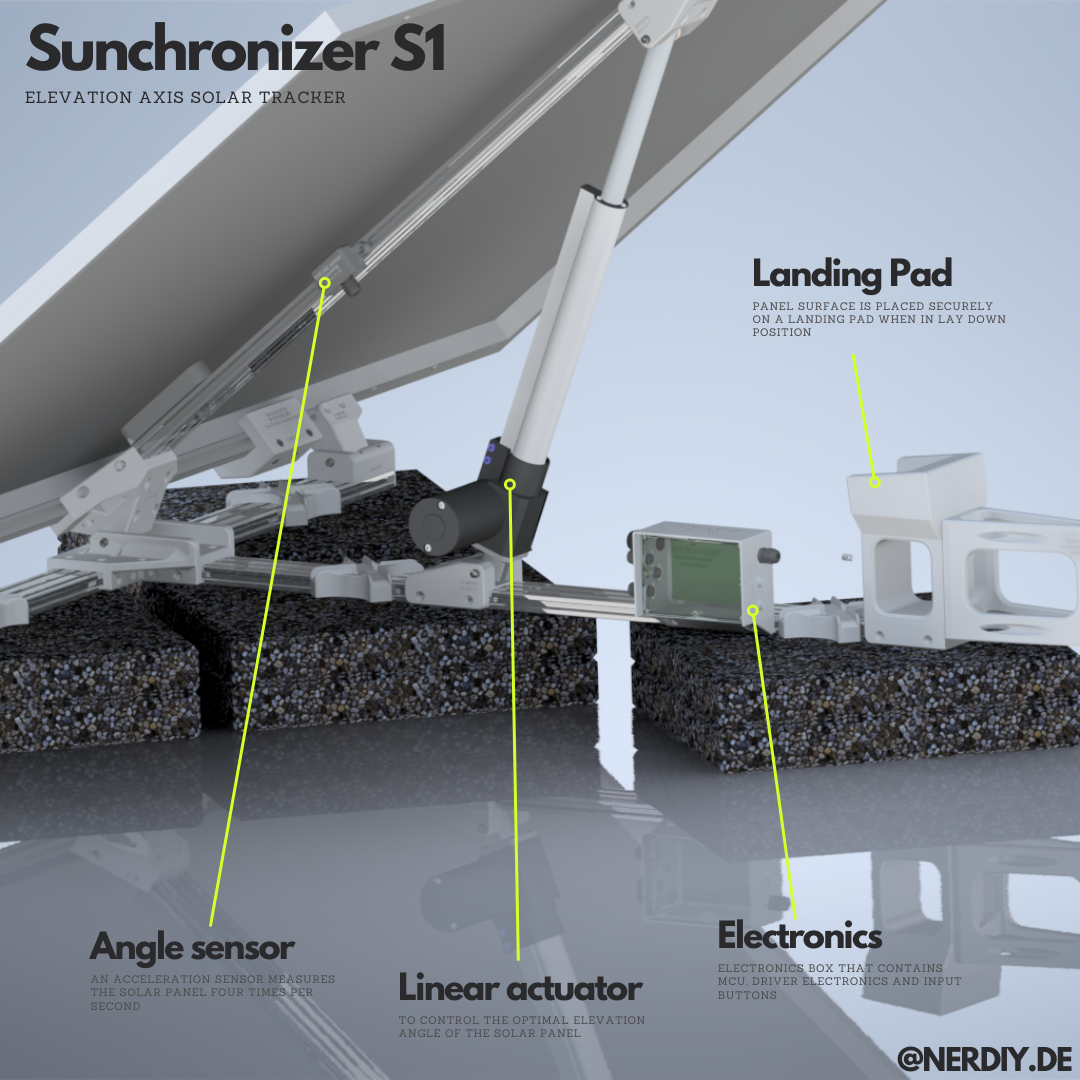
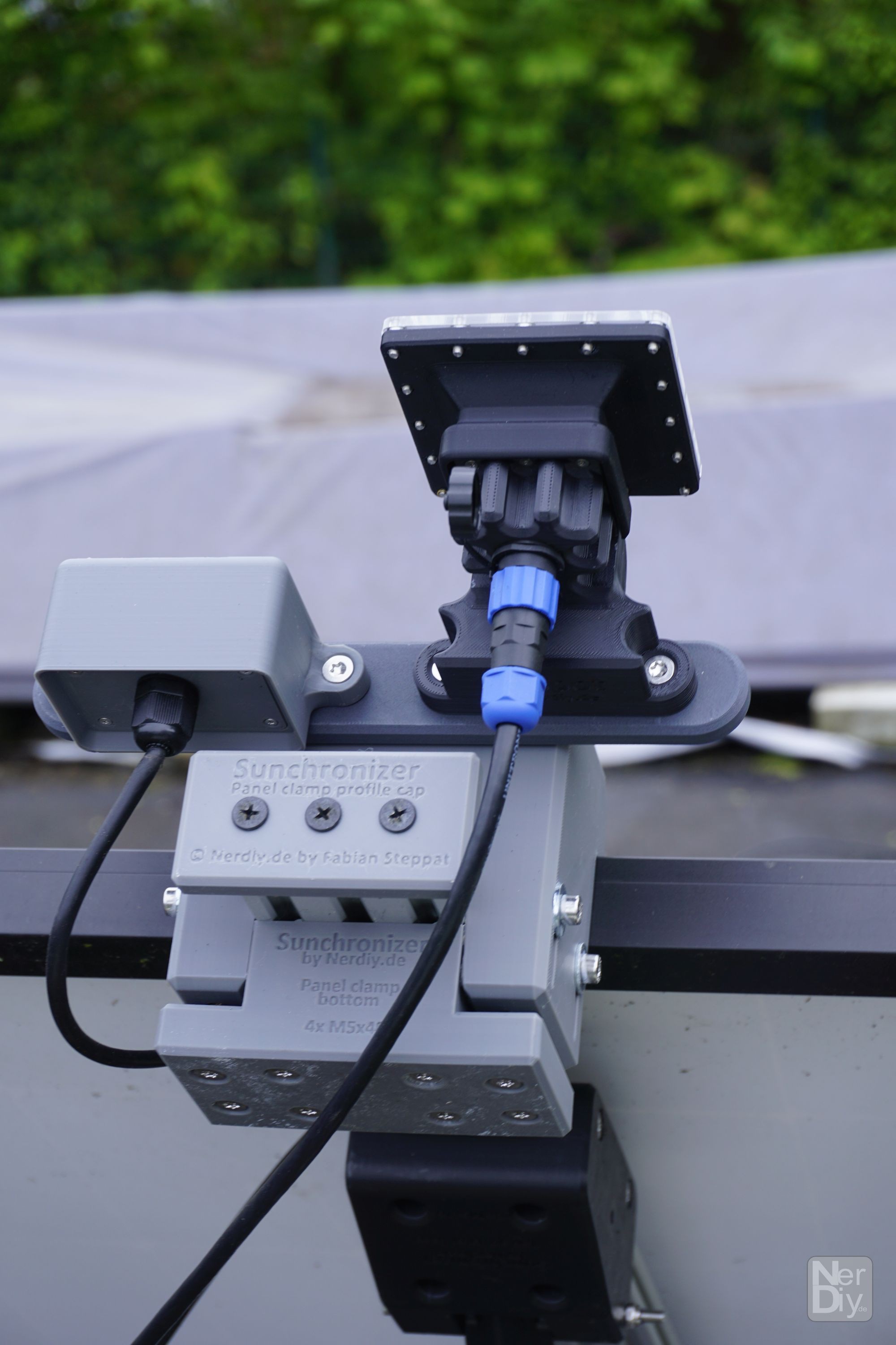
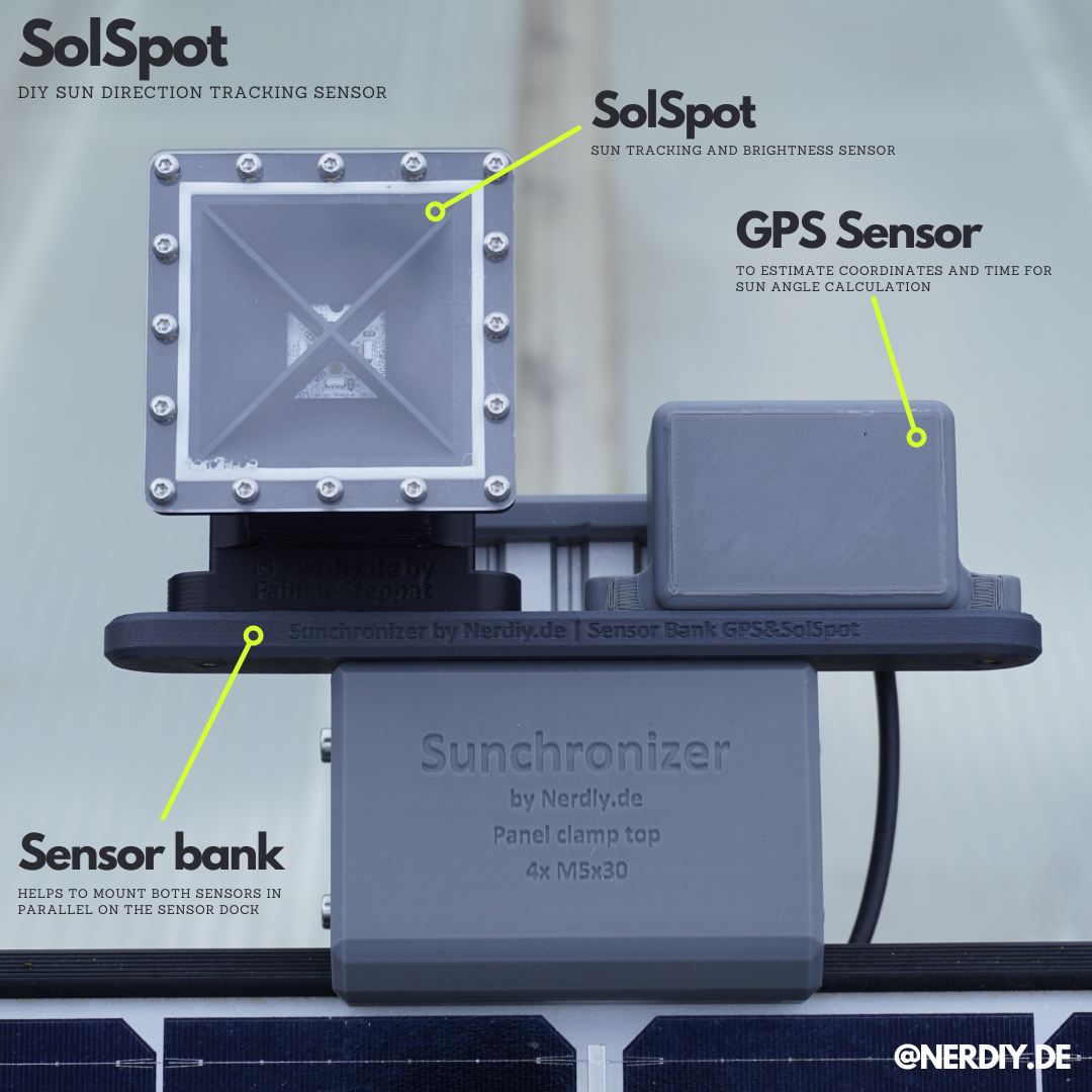
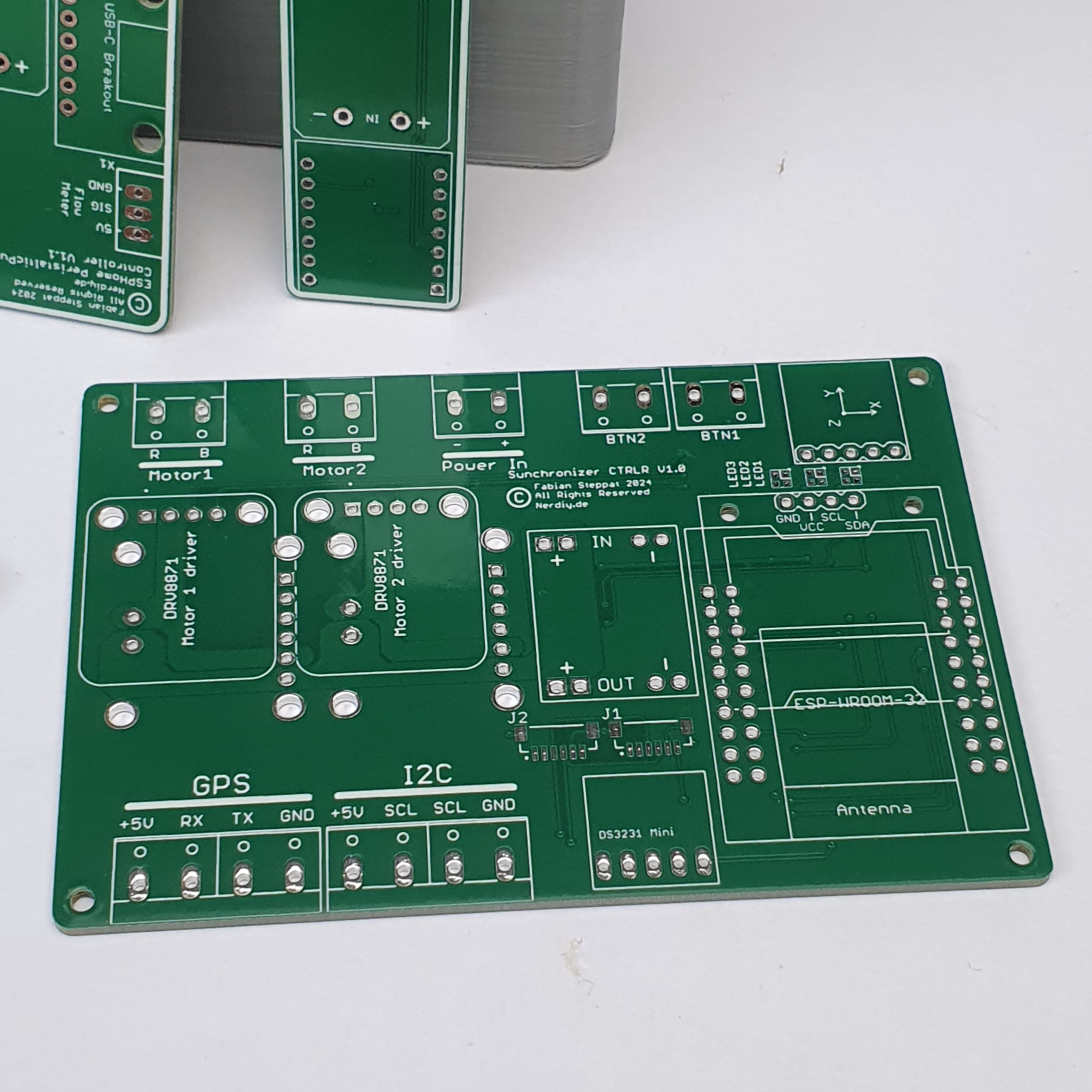
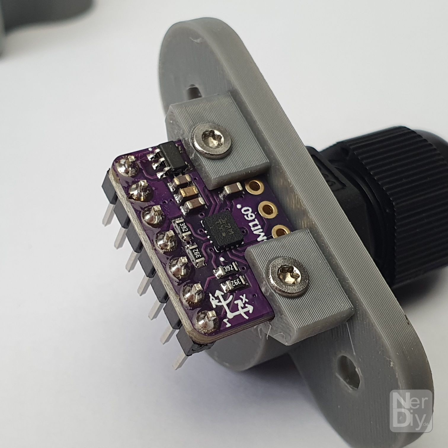
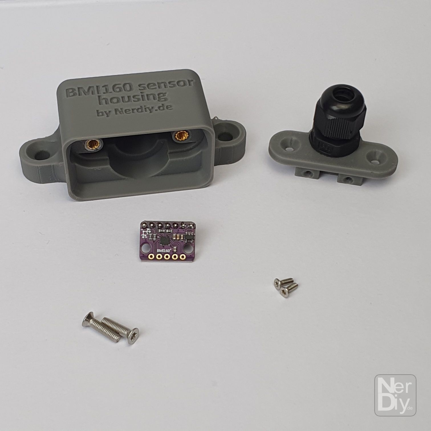
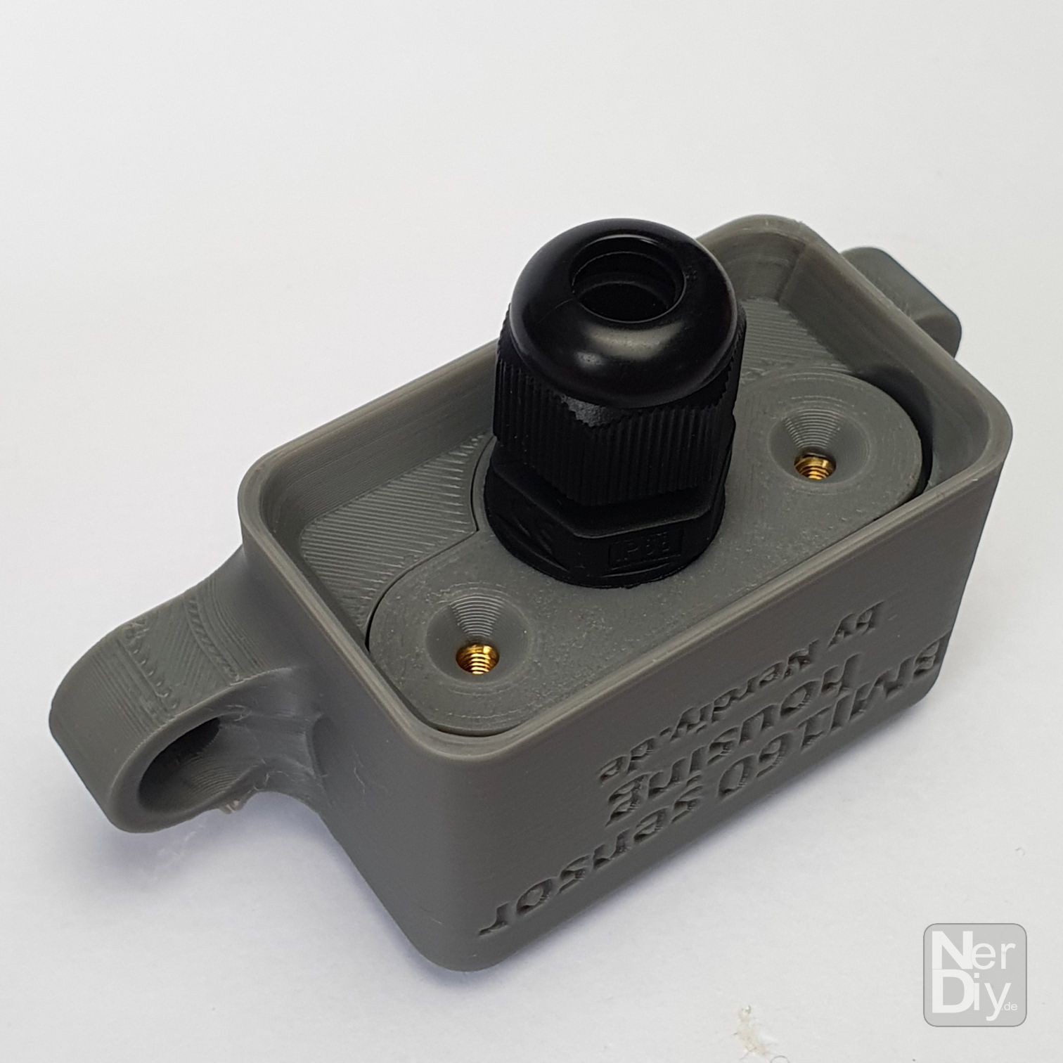
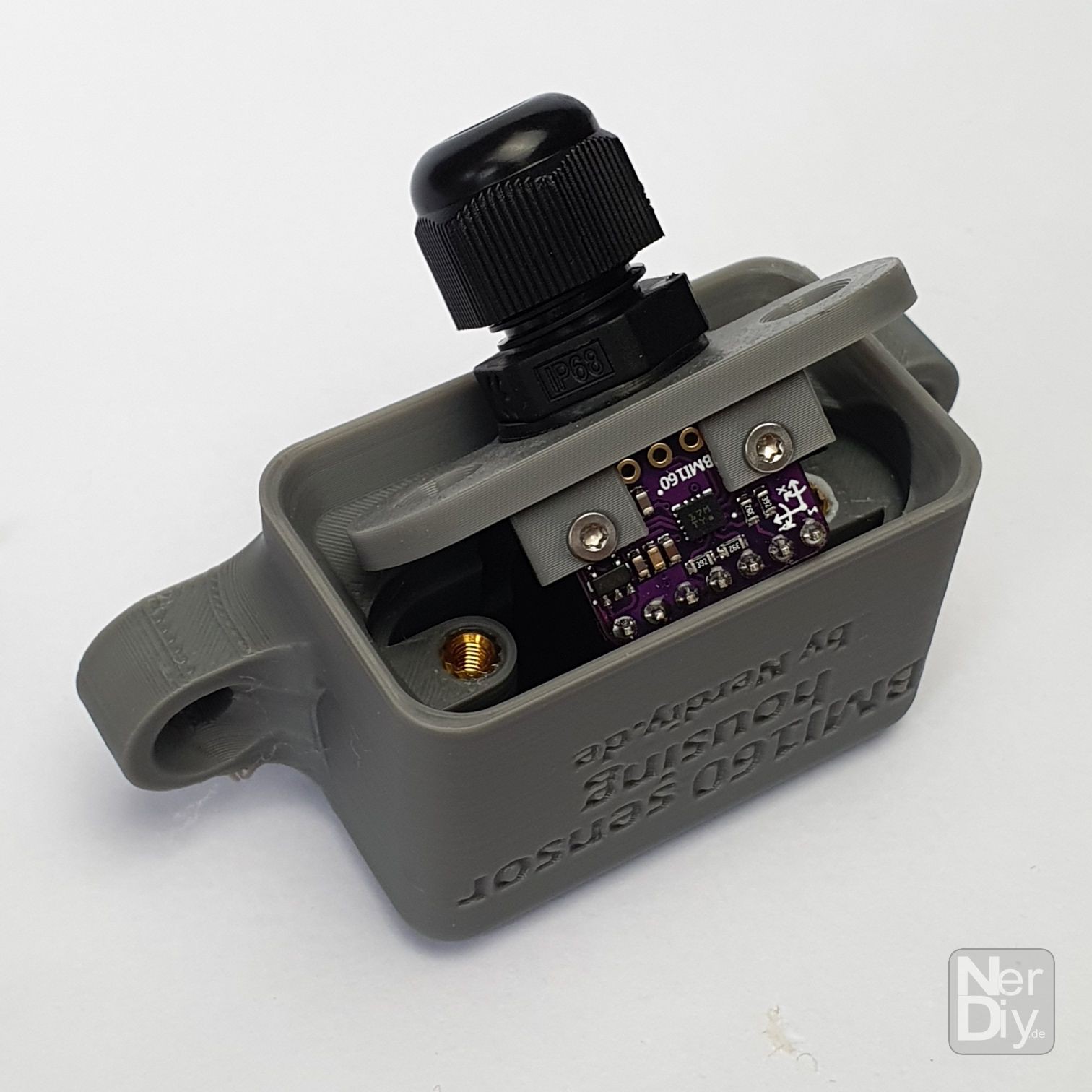
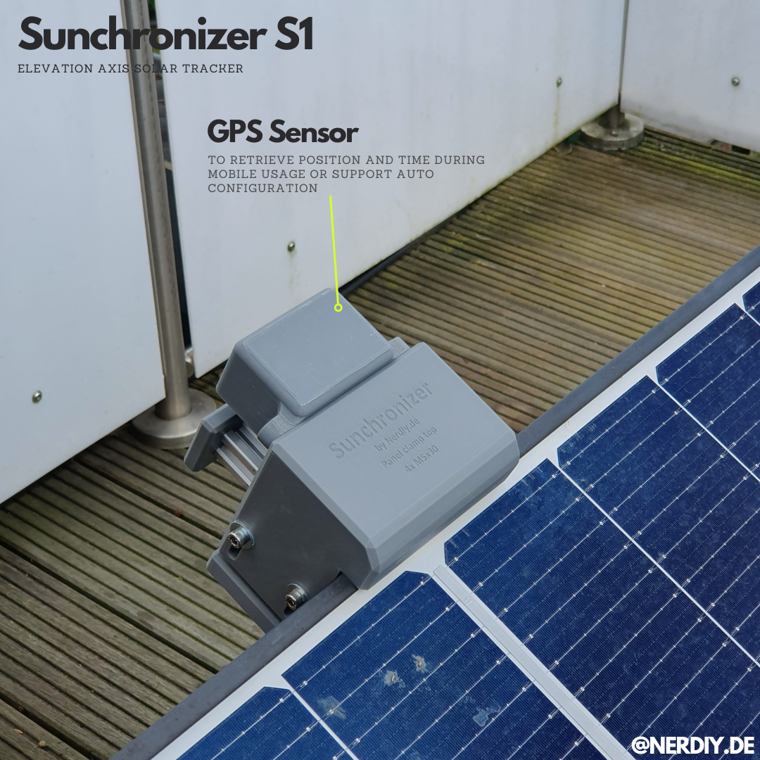
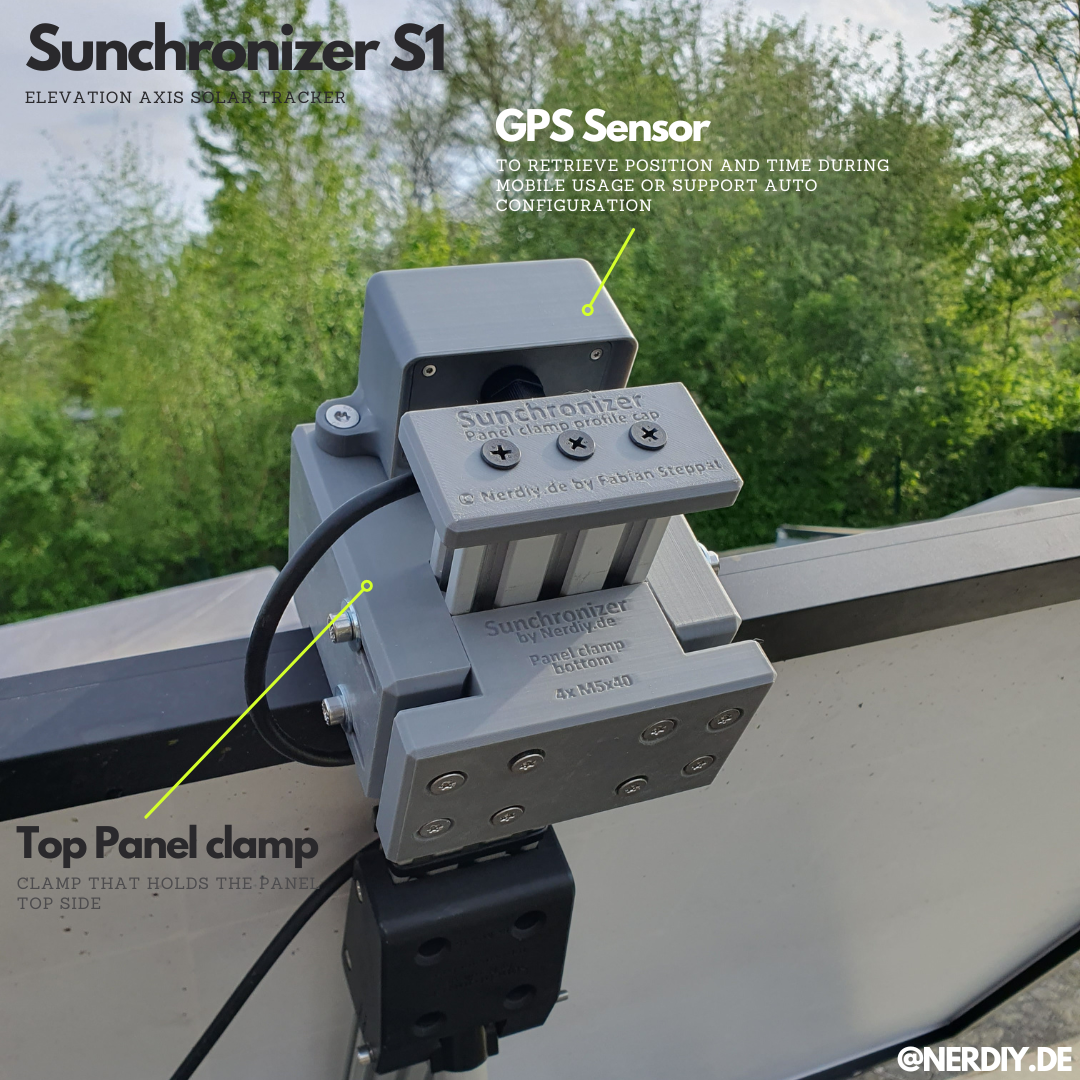
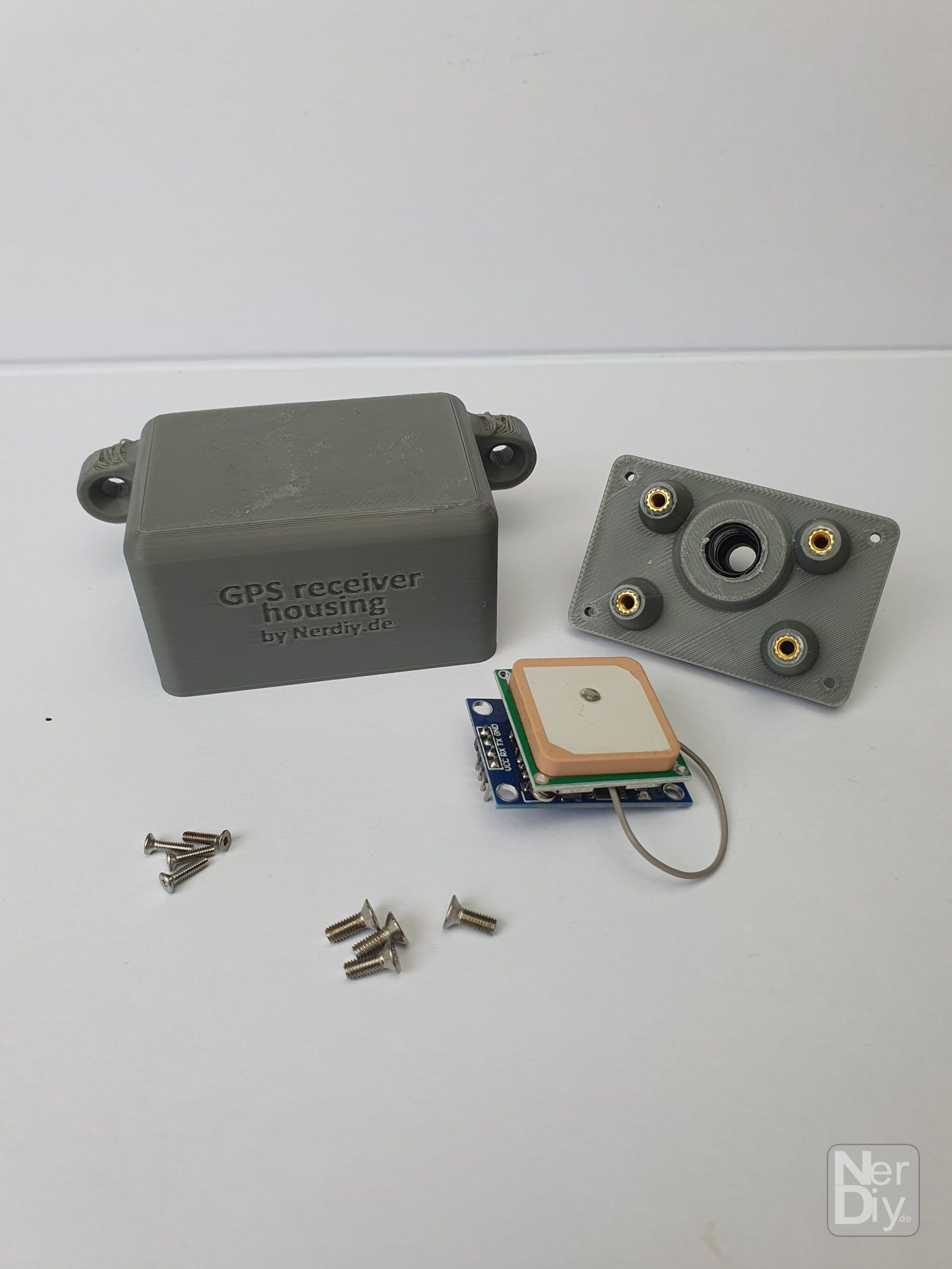
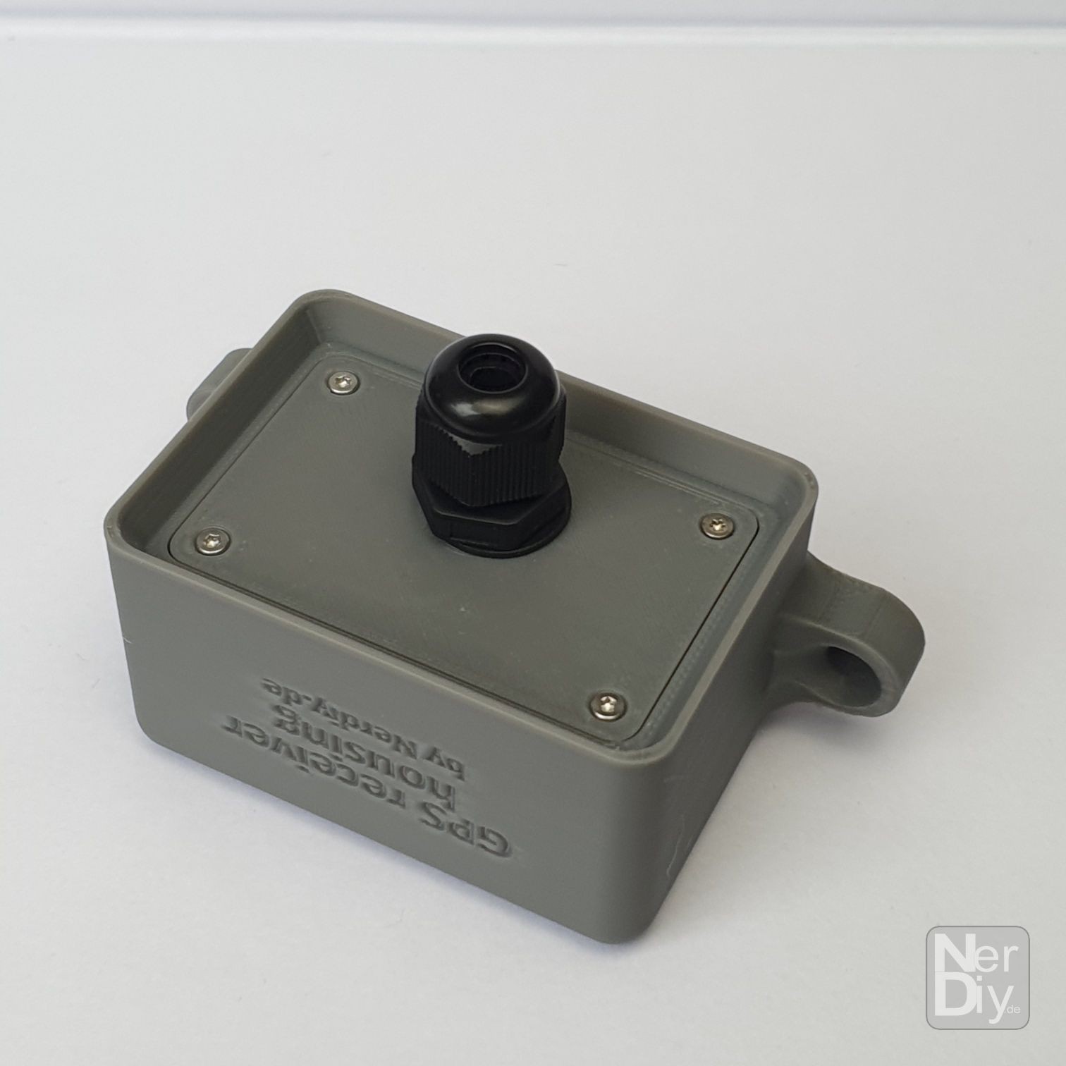
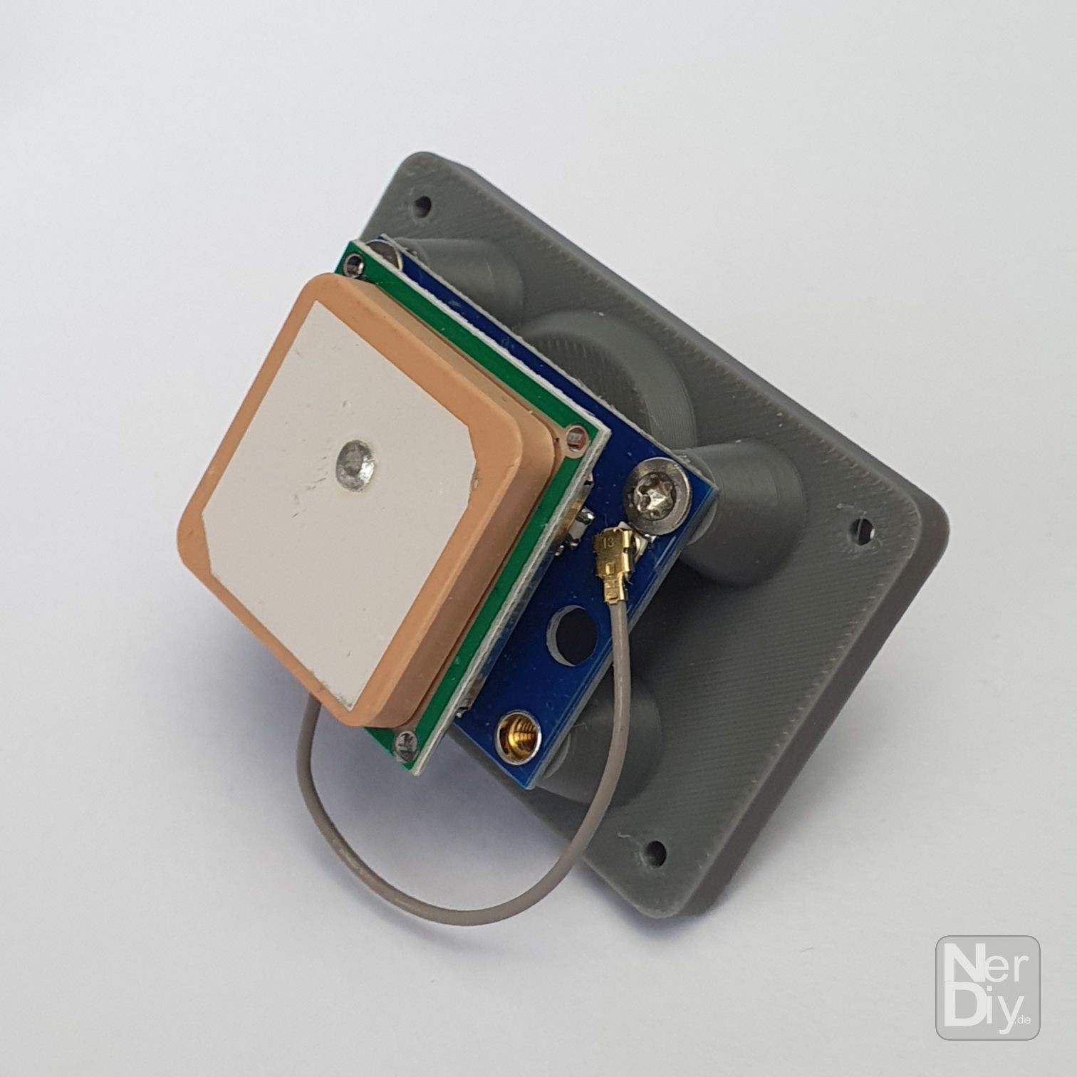
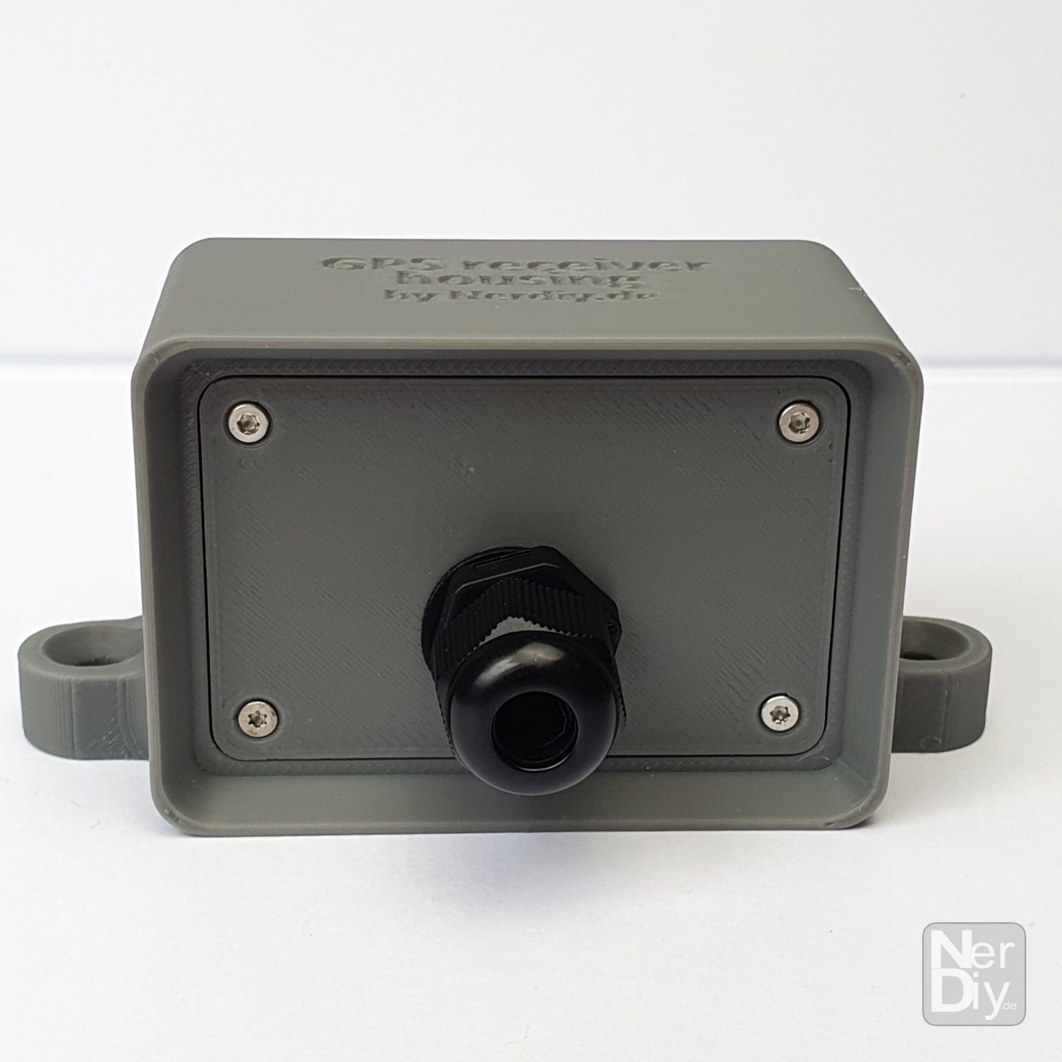
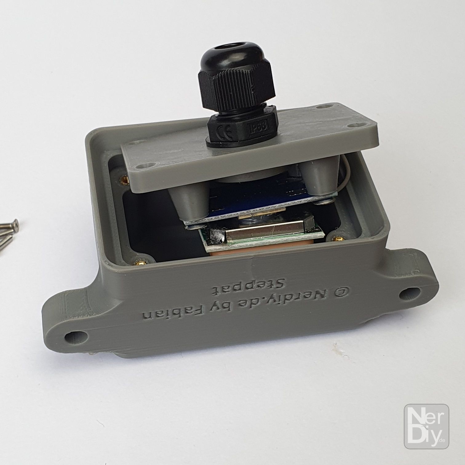
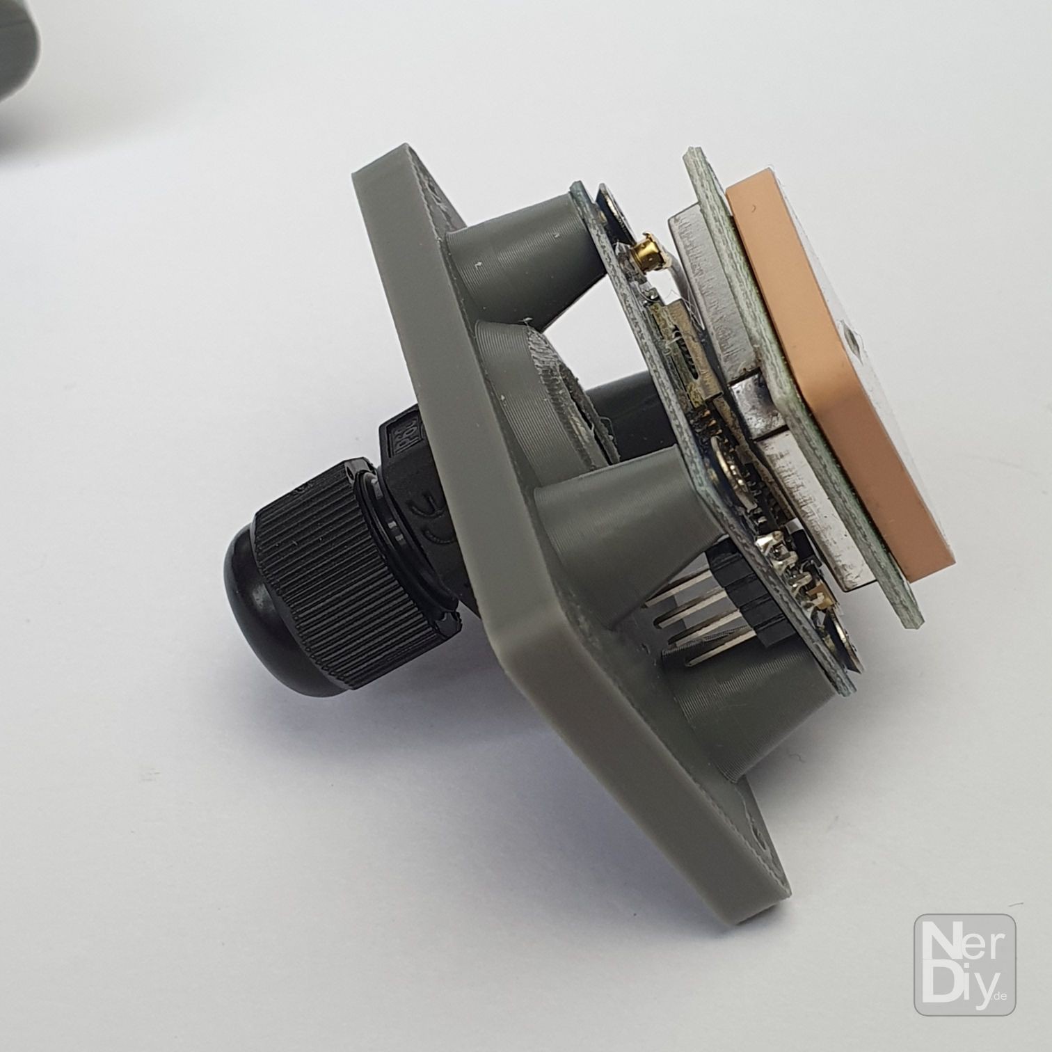
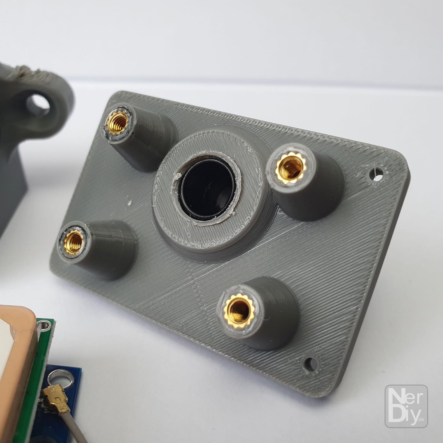
The axis is tracked using a 6000N linear actuator, which is controlled via an ESP32 and corresponding electronics. The firmware of the ESP32 is based on ESPHome and can therefore be easily integrated into HomeAssistant or many other SmartHome systems. The Sunchronizer can also be used independently of a connection to other systems. For example, the position can be obtained automatically via a GPS receiver, which means that the current time is also known. Based on this data (and the configured orientation (compass direction) of the Sunchronizer), the optimal elevation angle is then calculated and set. So that this can be set correctly, the angle of the panel is measured four times per second with an BMI160 acceleration sensor and adjusted accordingly if necessary.
Further Info and ressources:
- The latest state of the ESPHome configuration is available on my GitHub at: https://github.com/Nerdiyde/ESPHomeSnippets/blob/main/Snippets/Sunchronizer/sunchronizer.yaml
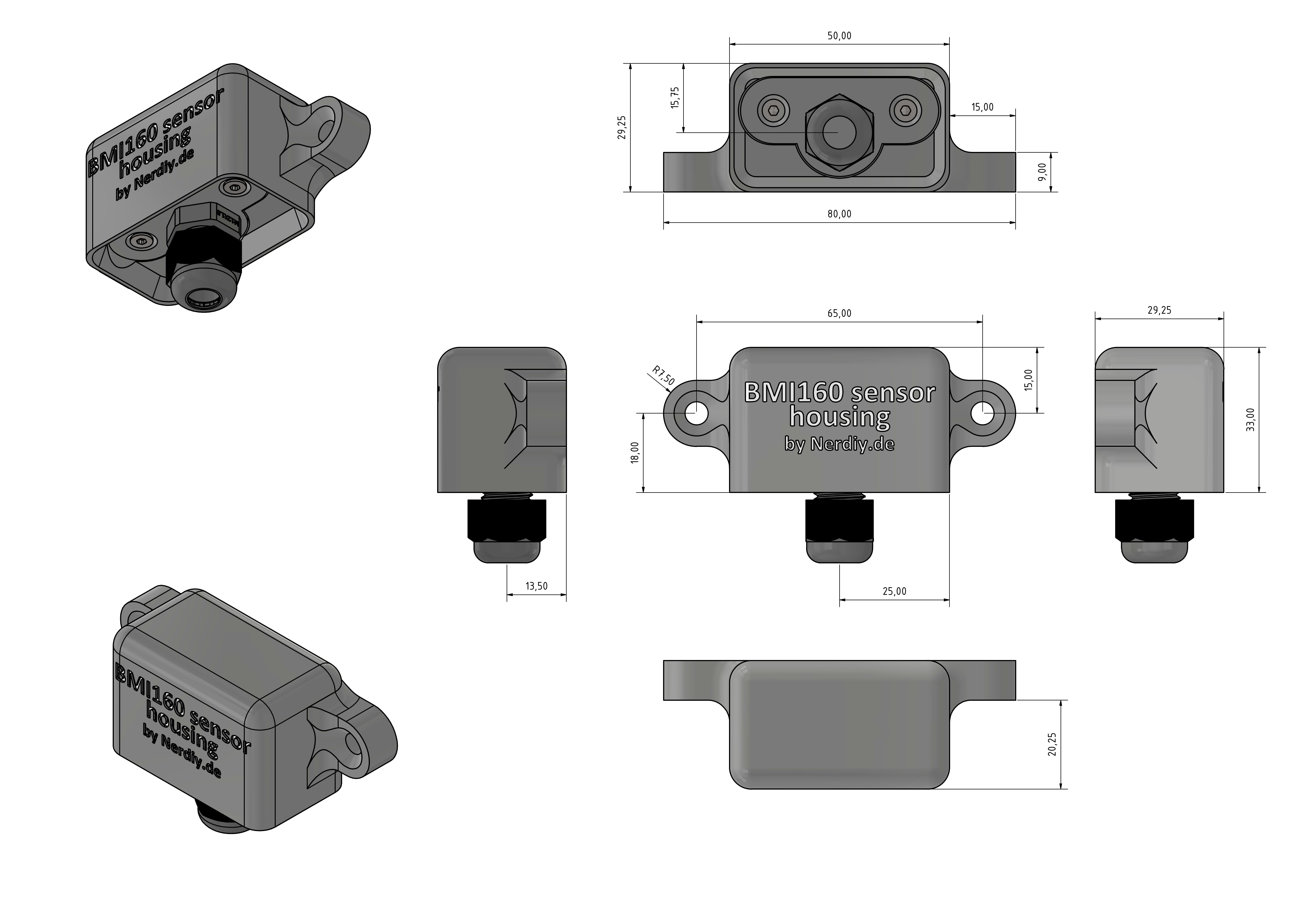
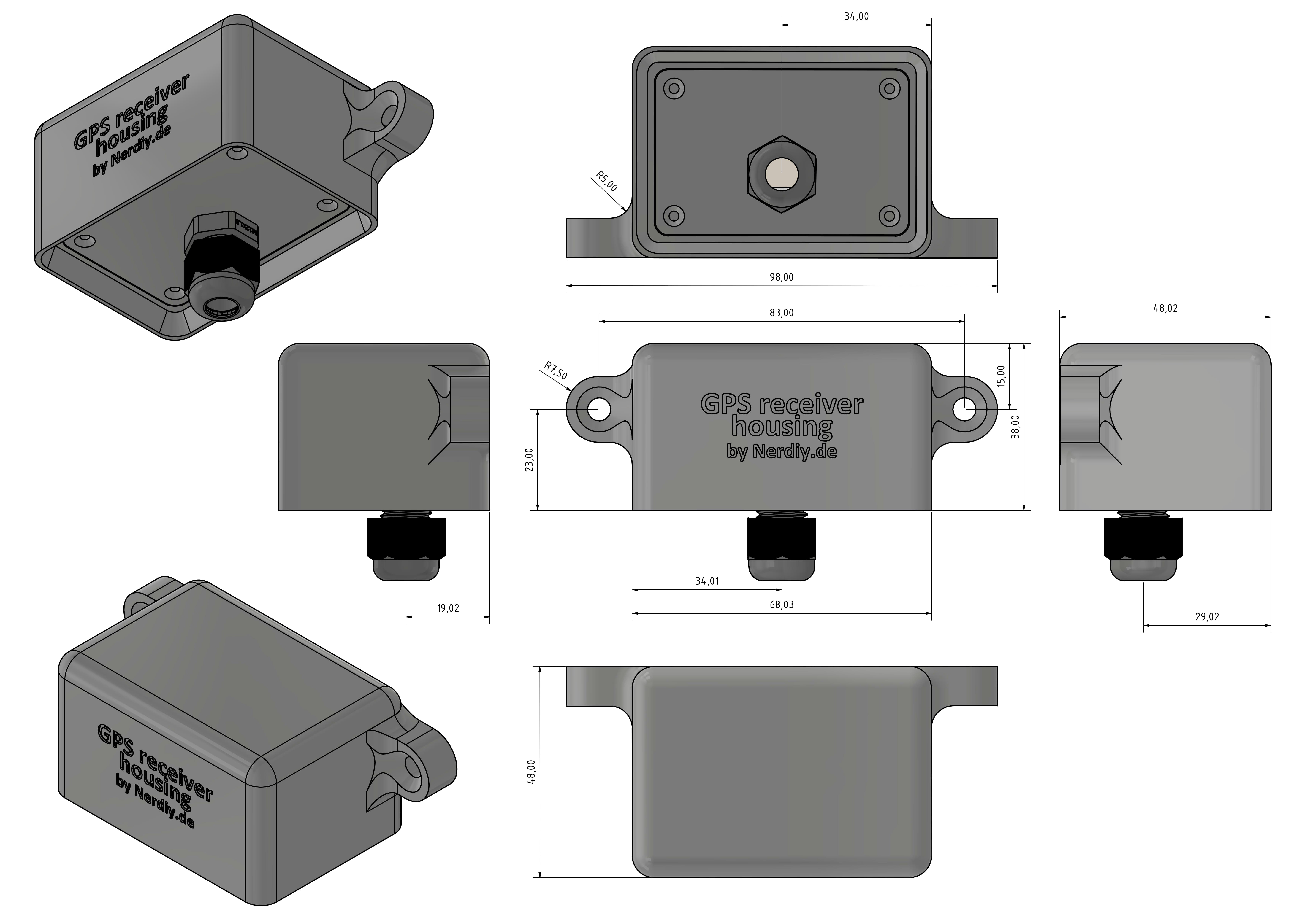
- The STL files, more technical data and dimensions are available here: https://nerdiy.de/en/product-2/sunchronizer-s1-400w-solartracker-fuer-elevation-achse-3d-druckbar-stl-dateien/
Support:
If you want to support me, you can do so by like on this project page, on Instagram or by donating a coffee. :)
Licenses:
Content that is not based on software/code: Unless otherwise stated, all works presented here that are not based on software/code are subject to the CC BY-NC-SA 4.0 license (attribution – non-commercial – dissemination under the same conditions 4.0 international).
You can find a summary here: https://creativecommons.org/licenses/by-nc-sa/4.0/deed.de
You can find the complete legal text here: https://creativecommons.org/licenses/by-nc-sa/4.0/legalcode.de
Software/code-based works Unless otherwise stated, all software/code-based works presented here are subject to the GNU Affero General Public License v3.0
You can find a summary here: https://tldrlegal.com/license/gnu-affero-general-public-license-v3-(agpl-3.0)#summary
The complete legal text can be found here: https://www.gnu.org/licenses/agpl-3.0.de.html

 hIOTron
 Jan
Jan
 Kevin Kessler