 Fabian
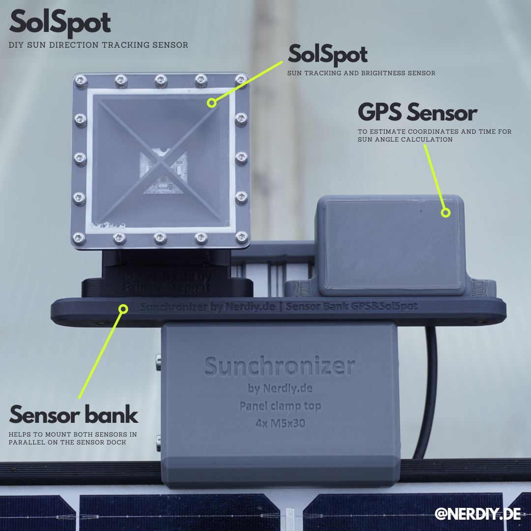
One thing is critical for proper and fast Solar Tracking: Measure the current lighting conditions. Therefore I designed my own Solar Tracking Sensor called "SolSpot" which you can see below.
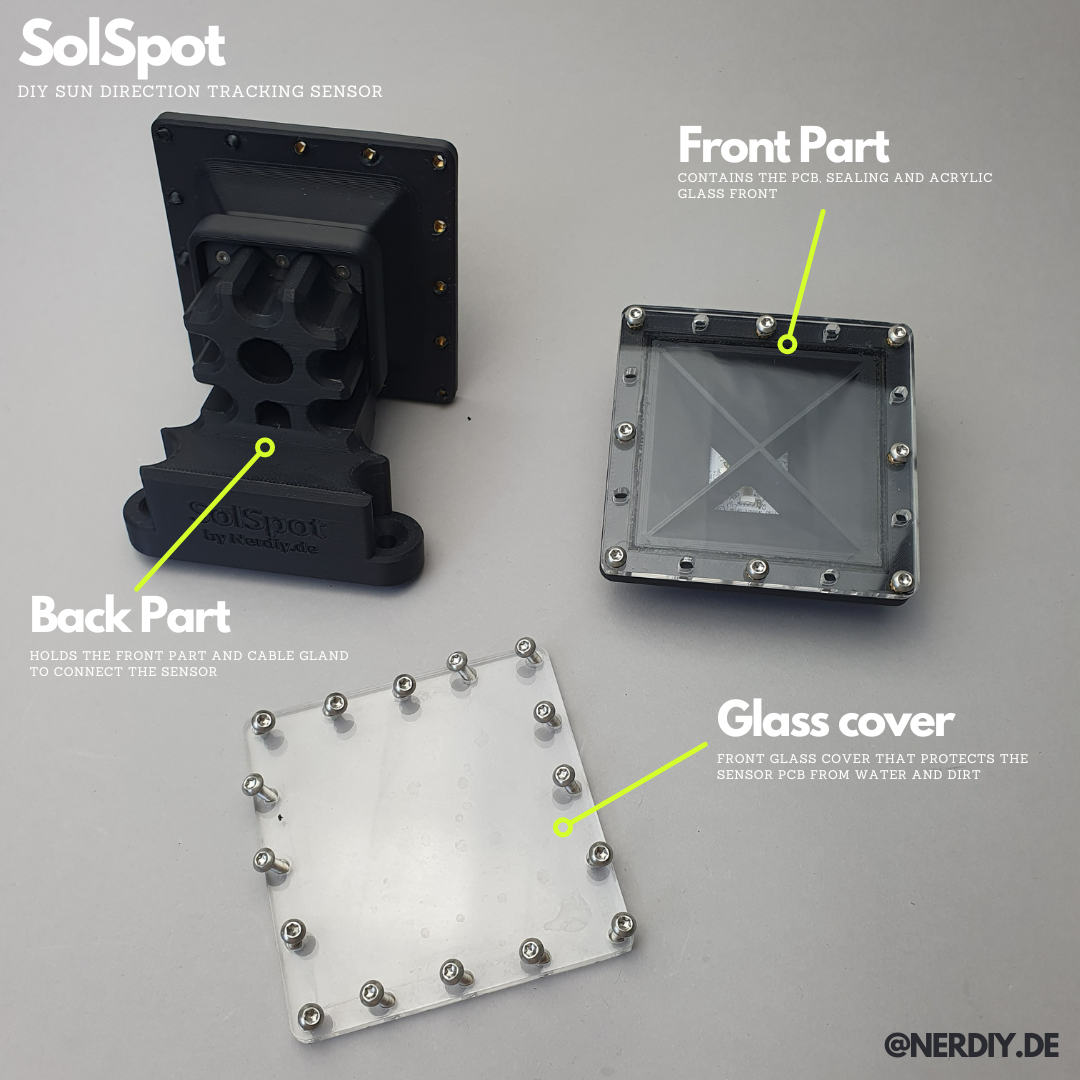
Below you can see my (current) finale state of the SolSpot housing. In order to connect the individual components together in a (hopefully) waterproof manner, I use a sealing ring printed from TPU. This is inserted into the grooves provided and clamped between the components. The watertightness of the front panel was particularly important to me because the sensor electronics are located directly behind it.
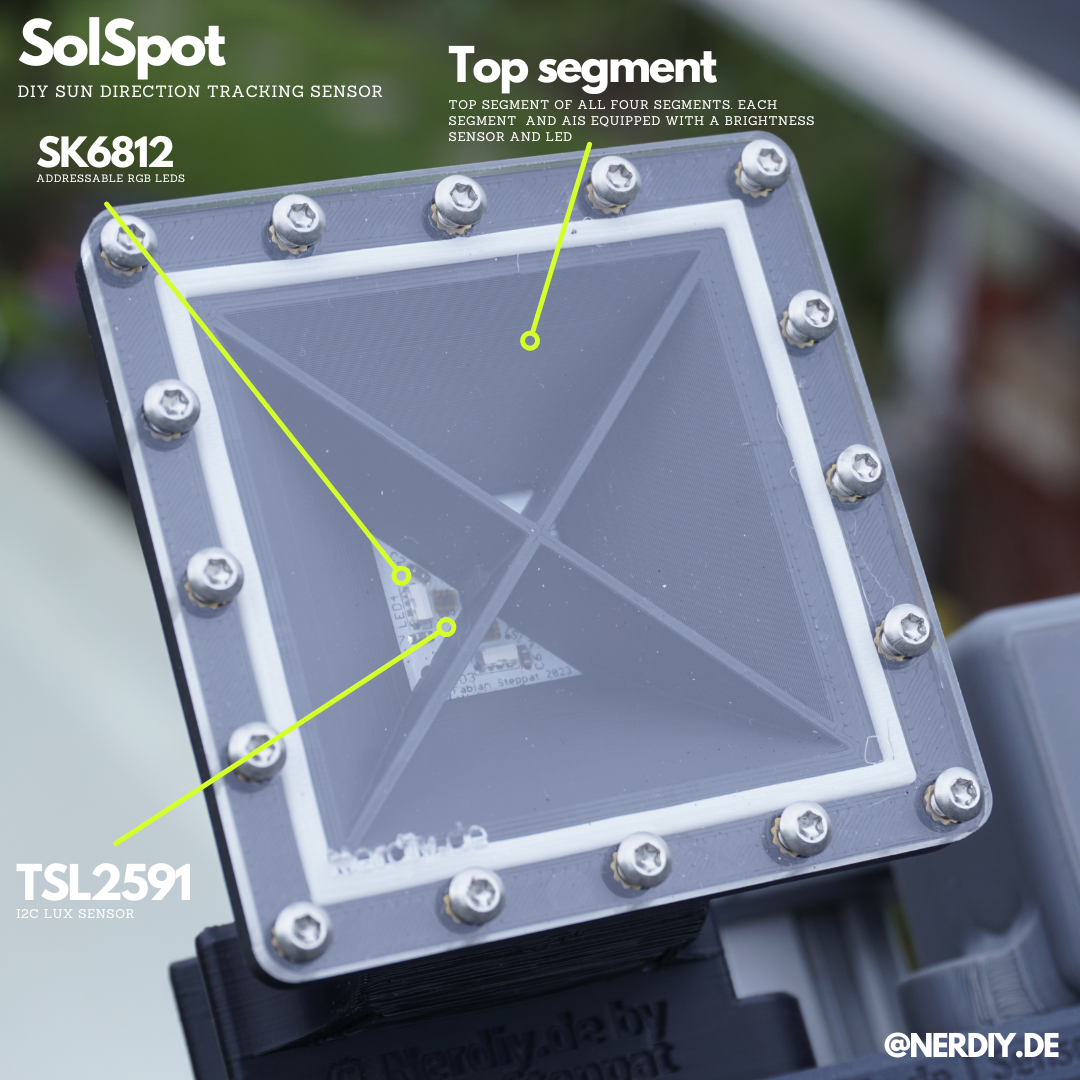
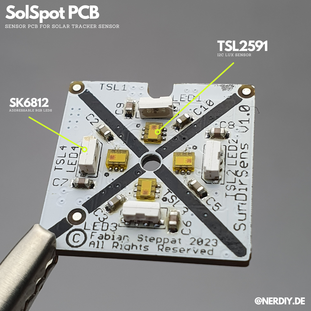
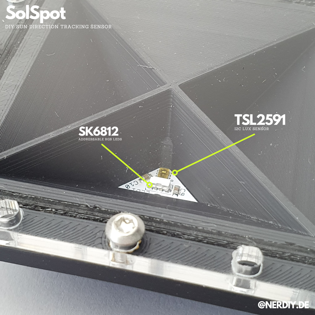
Below you can see a picture of the circuit board installed in the SolSpot Housing. Four TSL2591 light sensors are installed on it, with which the brightness in the respective sensor element and thus the alignment/direction of the sun can be measured by comparing the brightness in the different segments. Next to each light sensor I also installed an SK6812 Side LED. This allows the sensor to carry out a simple functional test (for example at night) to ensure that the light sensors are still working correctly. Many thanks to pcbway.com for assistance with this project by providing their PCB service.
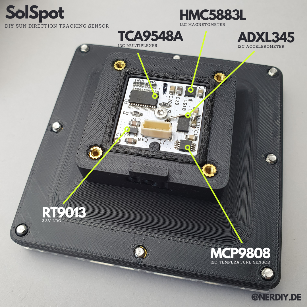
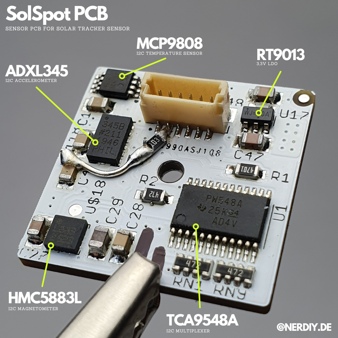
For the light sensors I use a TSL2591. These are read out via the I2C bus. Unfortunately, these do not have an adjustable I2C address. That's why I read the individual sensors via a TCA9548 I2C multiplexer. With this IC, an I2C bus can be multiplexed to eight different buses. Additionally an ADXL345 acceleration sensor and a compass are also installed.
Discussions
Become a Hackaday.io Member
Create an account to leave a comment. Already have an account? Log In.