I did the mental calculations and thought that it would take at least 5 hours to clean up the Coaxial8or R0, since solid plastic is difficult to remove, and then it would take another 2 or so hours to put everything back together again, as well as 1 hour for resolving anything that I didn't account for.
That's 8 hours. I've seen Stuff Made Here scan jigsaw puzzles, and suspect it won't be the first and only time I'd find myself in this situation now that I need to find a new gasket material.
I have instead spent 4 hours updating the design of Coaxial8or R1 to hopefully increase flow rate and prevent any future leaks from melting onto the surface of the heating elements.
Cartridge protection
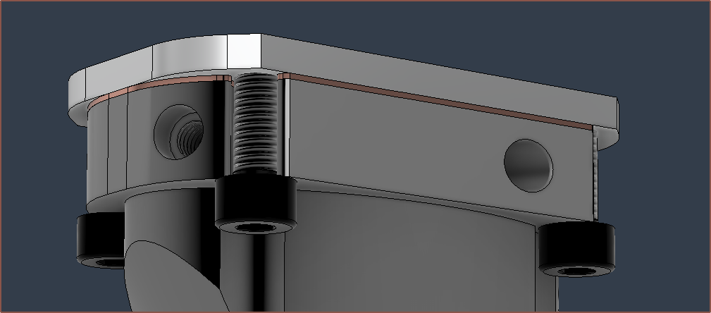
The wall between the cartridges and top face is 1.75mm, with the expectation that this will reduce to 1mm after the face has been flattened. I am considering increasing the CAD thickness to 2mm.
I think I now understand what I've heard in the past about "safe failure modes", in that in the event that the system fails, at least it fails nicely. Putting the cartridges on the underside means that I could have the heatblock heated when cleaning off plastic. The only concern with this solution is that it's possible for one of the heater cartridges to fall out onto the print if not sufficiently secured.
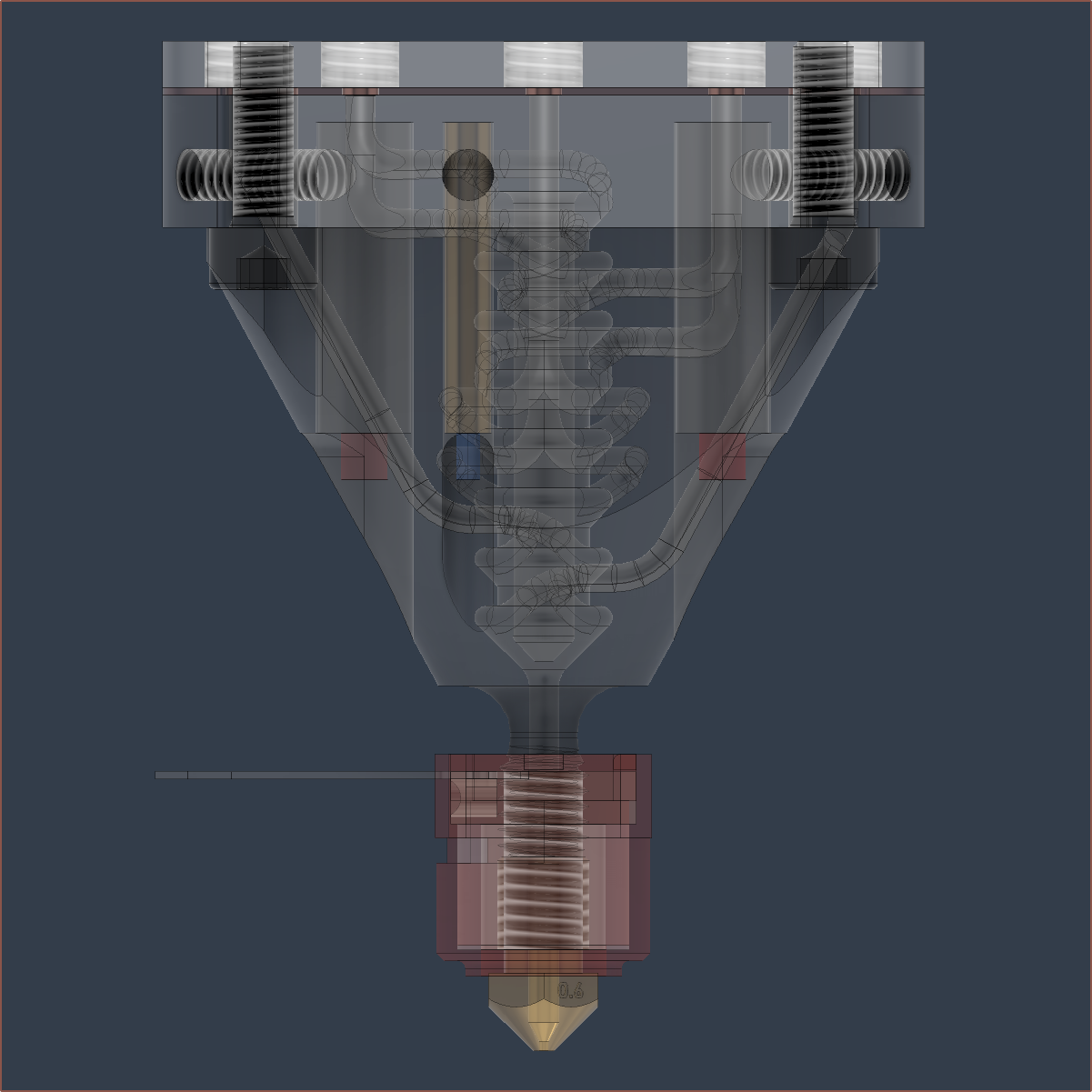
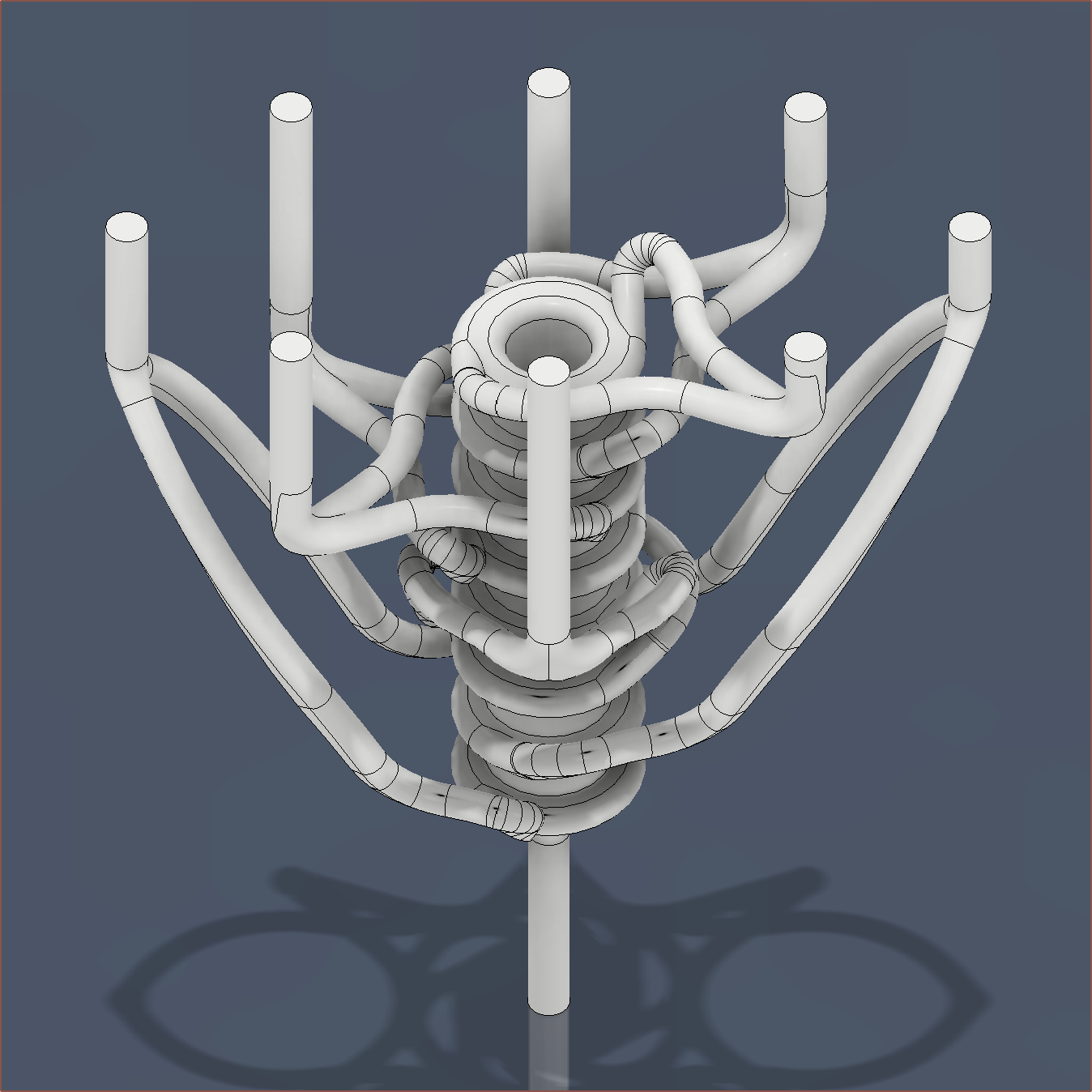
New pathways
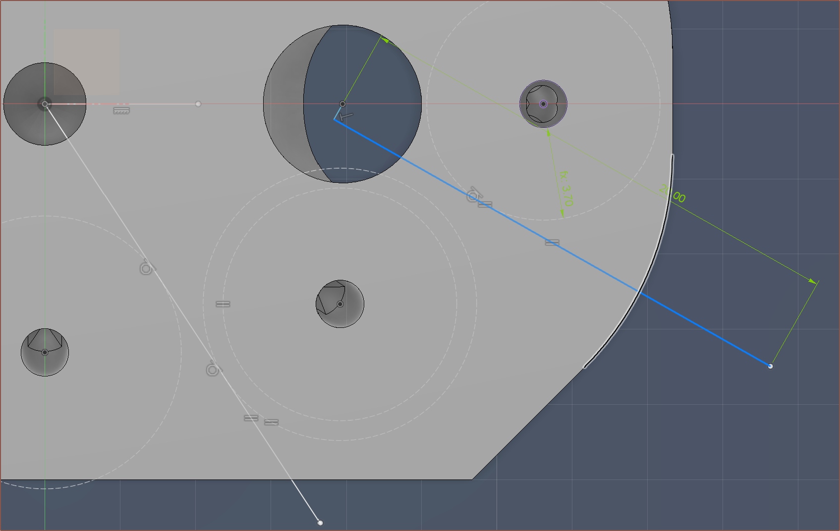
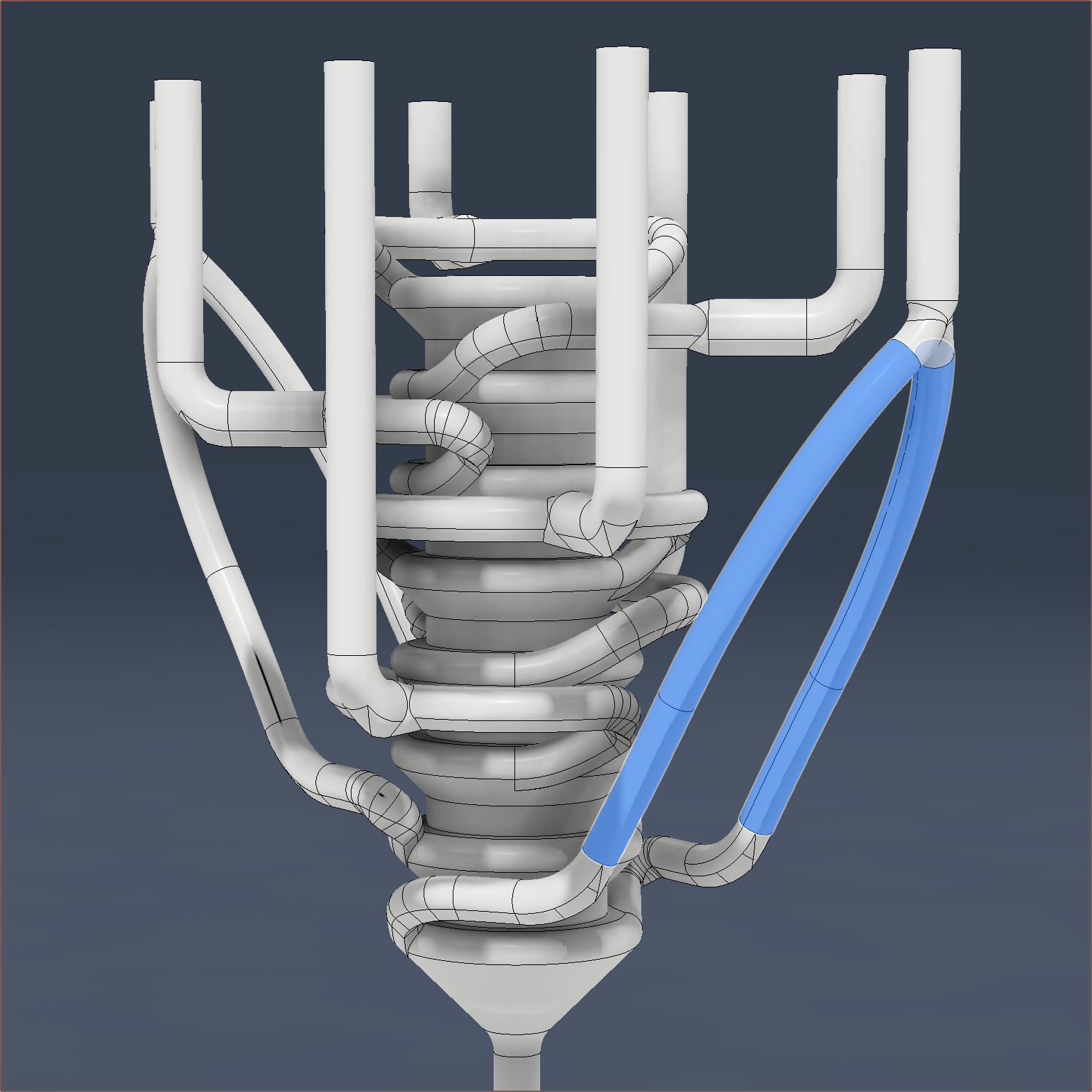
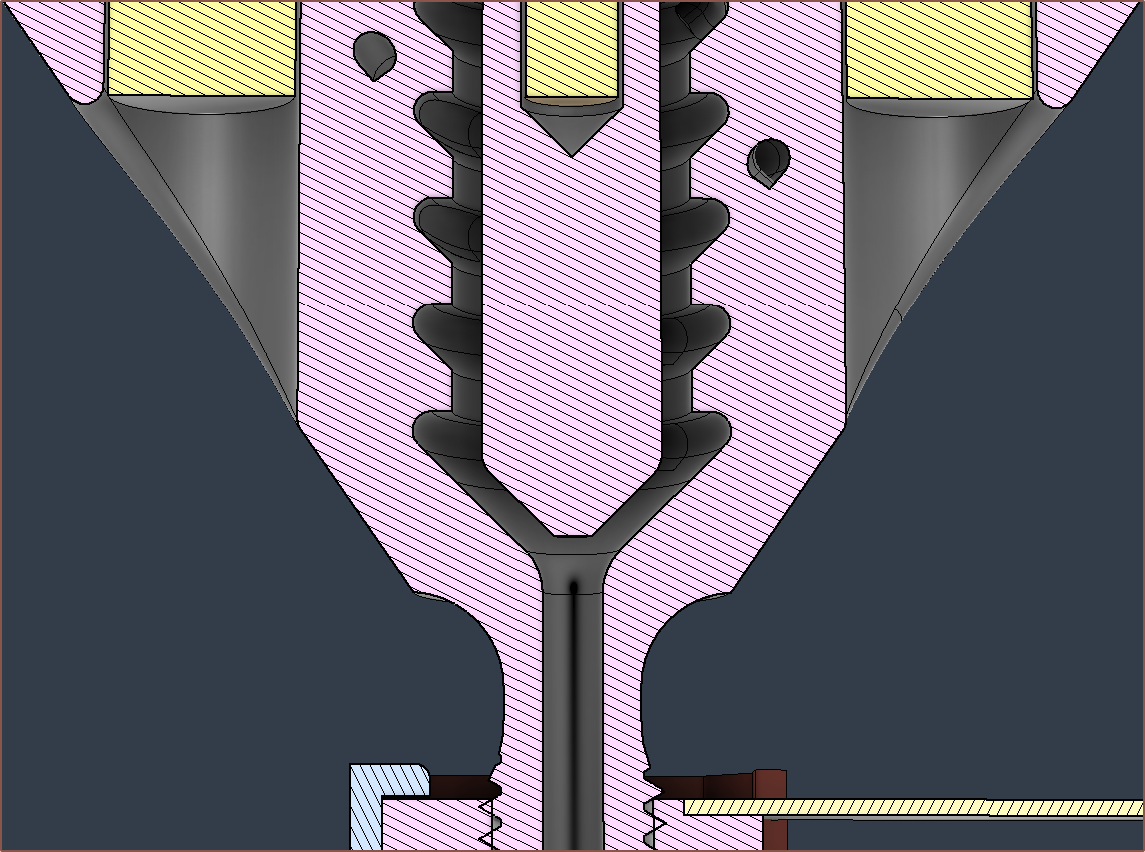
As you may be able to see, I've now replaced the T-like intersection between the major and minor channels for more of a Y-like intersection:
Since the thermistor is no longer in the centre, I've also reduced the diameter of the internal column to 4mm. I still feel like it's important to give the molten material something solid to build upon, especially when the main coaxial-ising section is 30mm long. I tried to reduce it but I wasn't able to. At least with this diameter reduction, the cross sectional area drops from about 20mm3 to 14mm3, which should notably reduce the amount of internal material.
Other things
Bounding box is now 49 x 29 x 49mm XYZ and the heatblock is 23,200 mm3.
I also tried to make the M6 thread more printable but Fusion generated so many faces and froze when I tried to offset them.
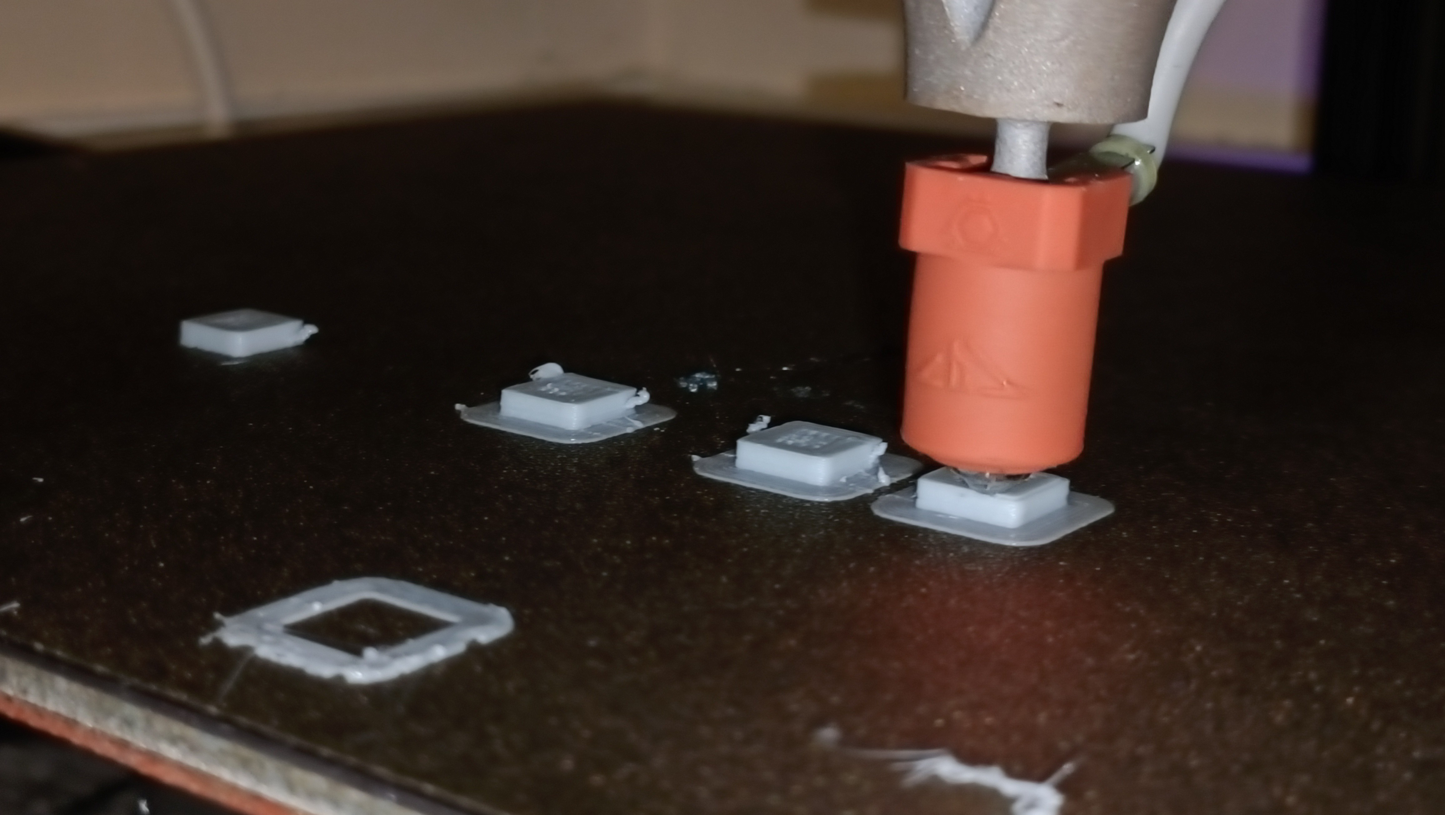
I think the test octogon prints add a nice bit of flair to this image.
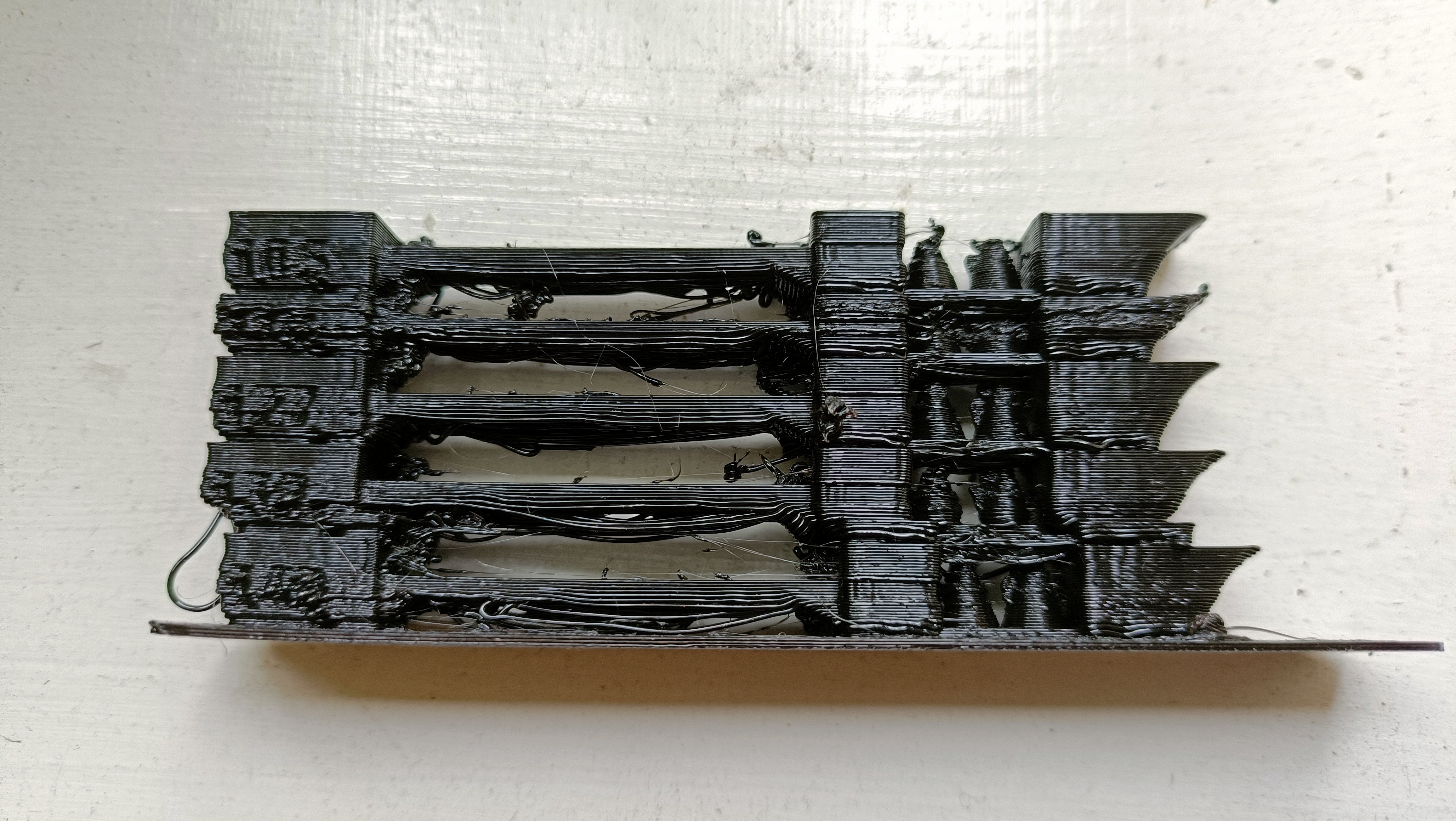
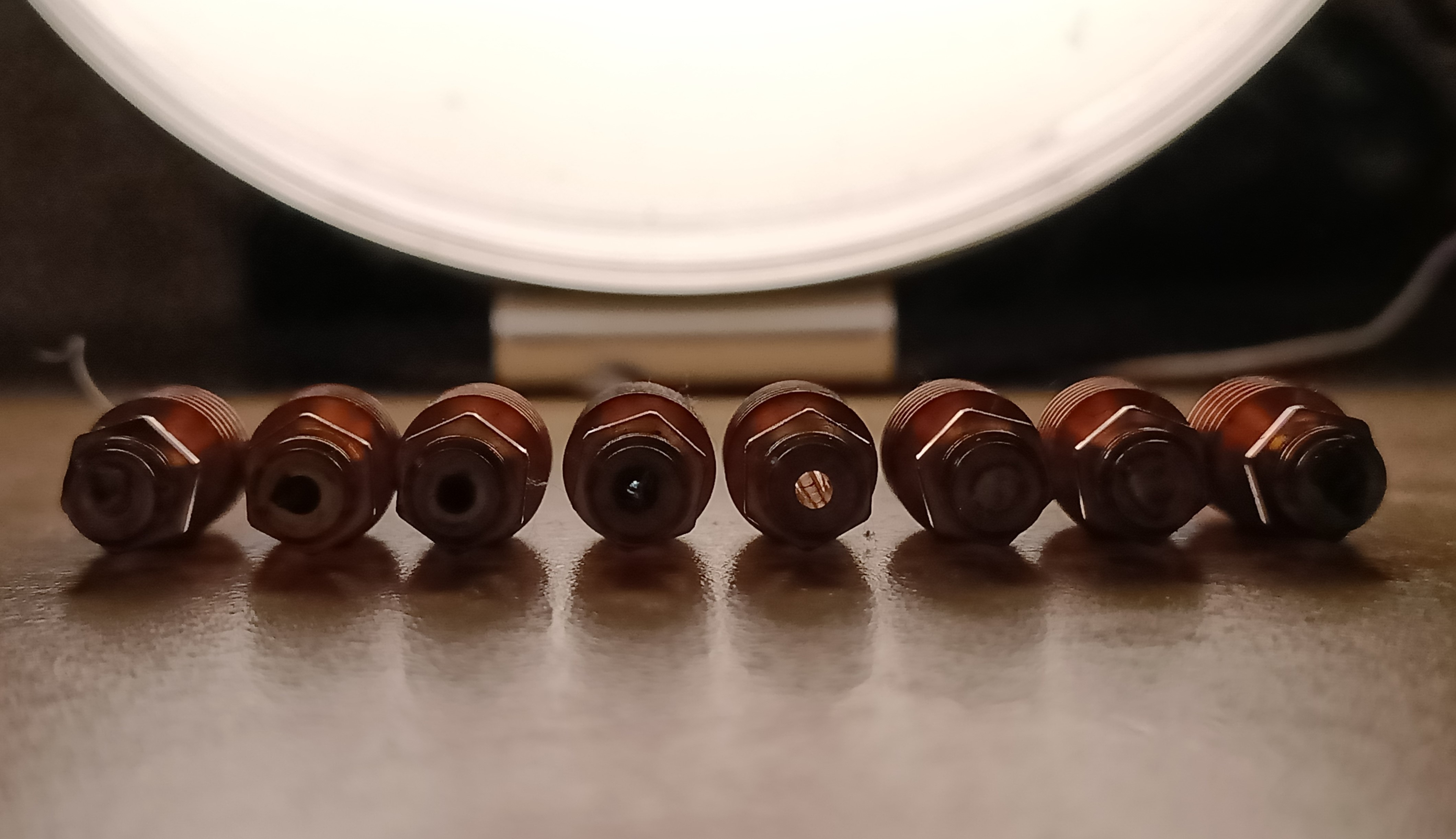
The above picture of all 8 heatsinks neatly in a line probably gave it away if the title didn't already, but it's ovur and I've dissassembled the Coaxial8or hotend.
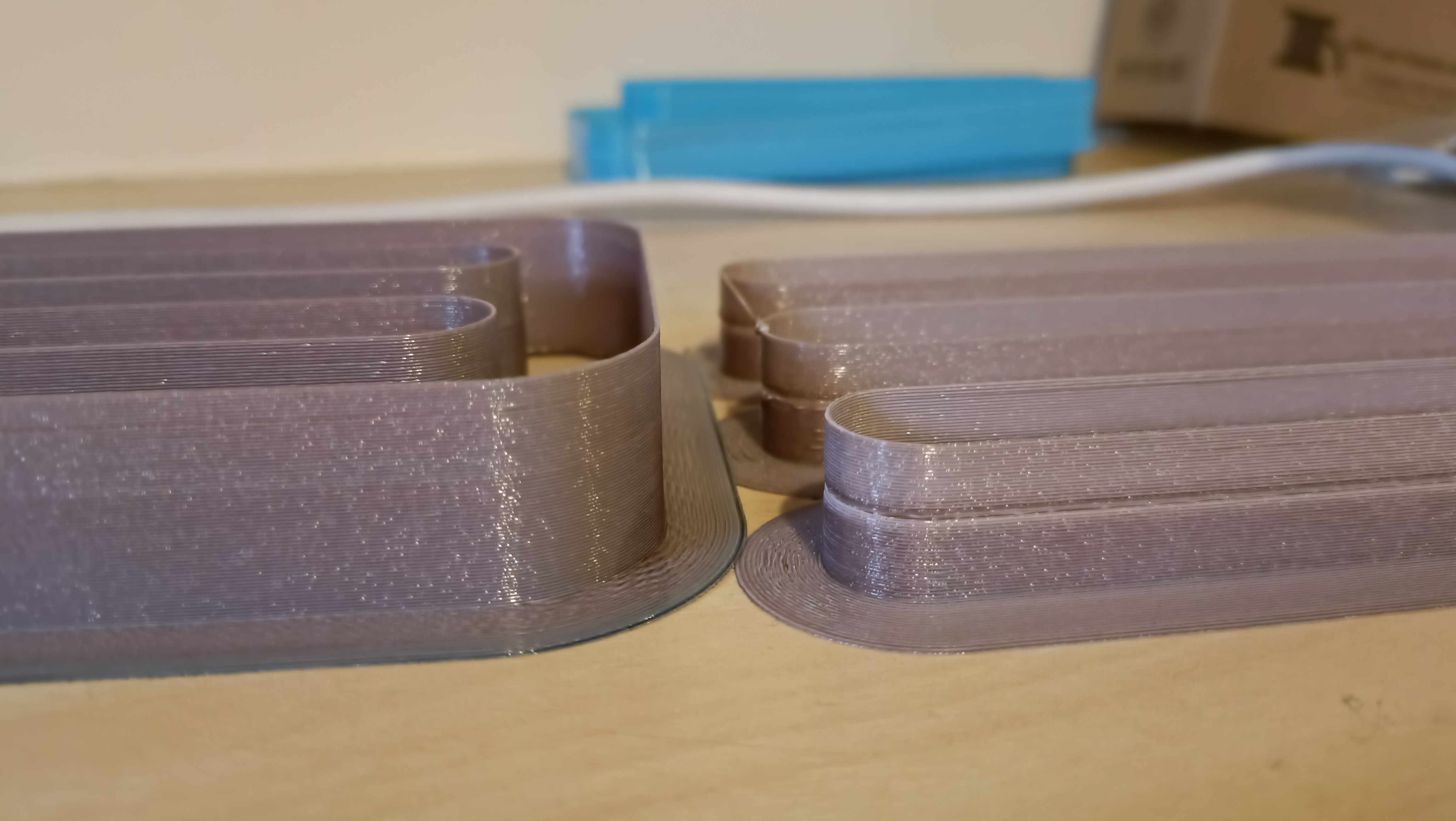
Extrusion (and colour uniformity) tests
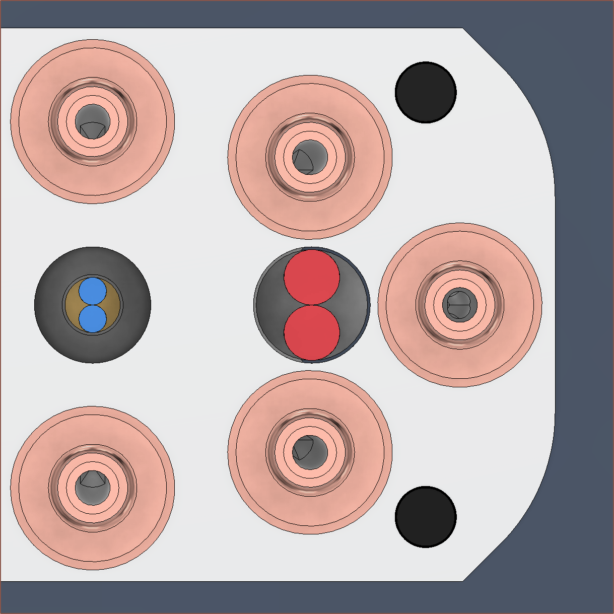
I started today with an extrusion test to get some real numbers for volumetric flow rate. So that I could also finally answer the question of "Does it coaxialate?", I decided to create a virtual filament of white + some other colour.
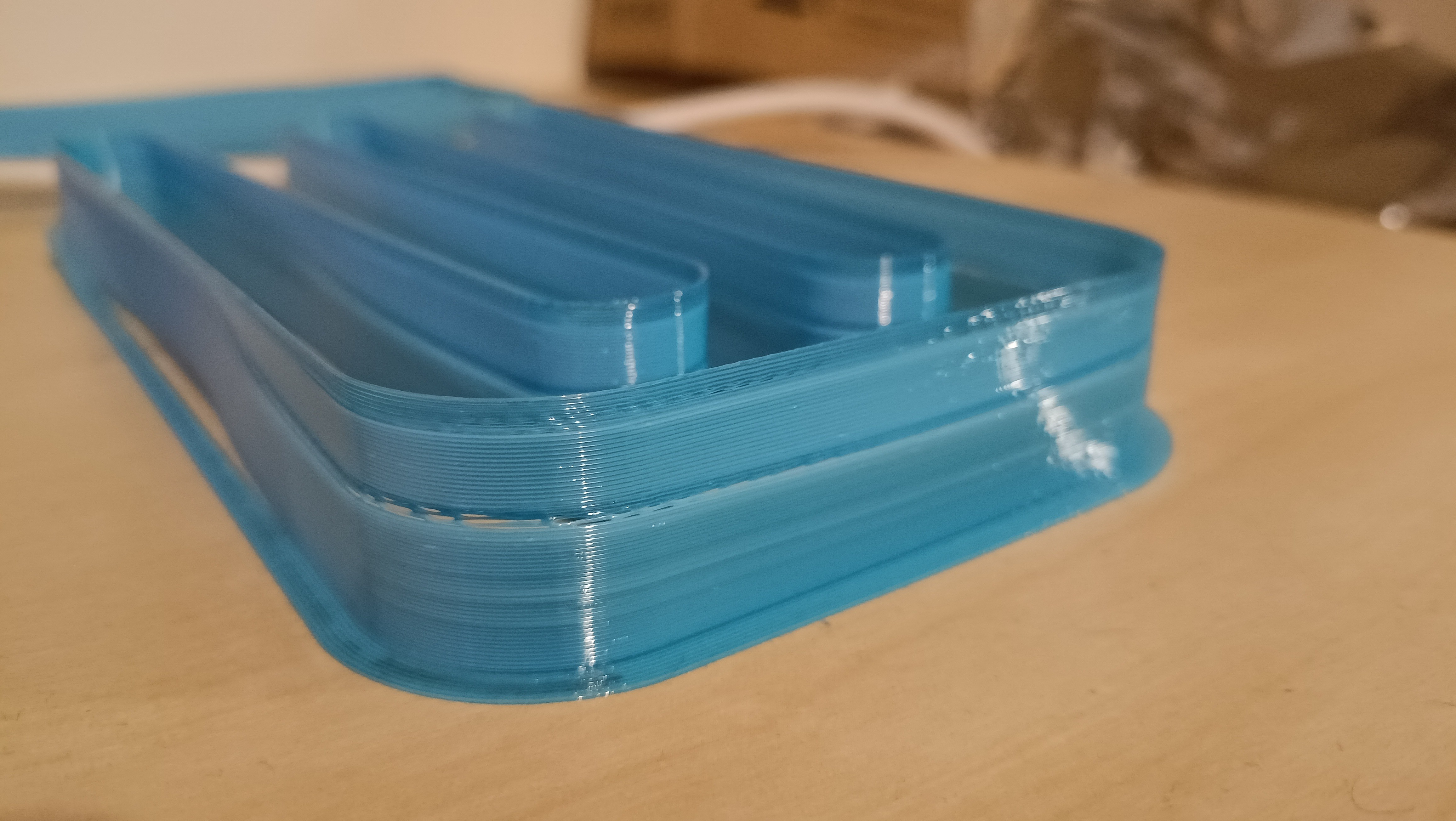
First I tested white encased in blue on channel 7 and 8, thus white was in 7 and blue was in 8 and they were a 50/50 mix. I also decided to create a purge line GCODE in PrusaSlicer:
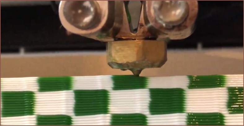
Then I started the print and quite quickly had to slow it down to 35% because it wasn't working all that well. I managed to get up to 90% speed though. My settings were 0.4mm layer height, 0.6mm nozzle, and 90% speed would correspond to 54mm/s. The good news is that it does seem to coaxialate, and looks consistent when the nozzle is travelling up and down the Y axis.
I cancelled this print not because it looked like it was about to warp off the bed, but because I noticed that there was a black blob of molten plastic seemingly oozing out the top of the CHC Pro and went to clean up and reseat the nozzle.
After levelling the bed so that both the edges and centre were of equal spacing to the nozzle, I tried again at 54mm/s but had to slow it down again to 90% speed, meaning that I'm probably fine at 48mm/s but 54 is at the edge of reliability. PrusaSlicer says this corresponds to 11.4mm3/s, which is very low. I was expecting that this design would be at least in the 30s. Additionally, the extruder for the white filament stopped turning for the last 2mm for some reason, so the very top is just transparent blue. Noticeably, the X direction is a slightly darker shade of blue. It's very slight though and I've got to
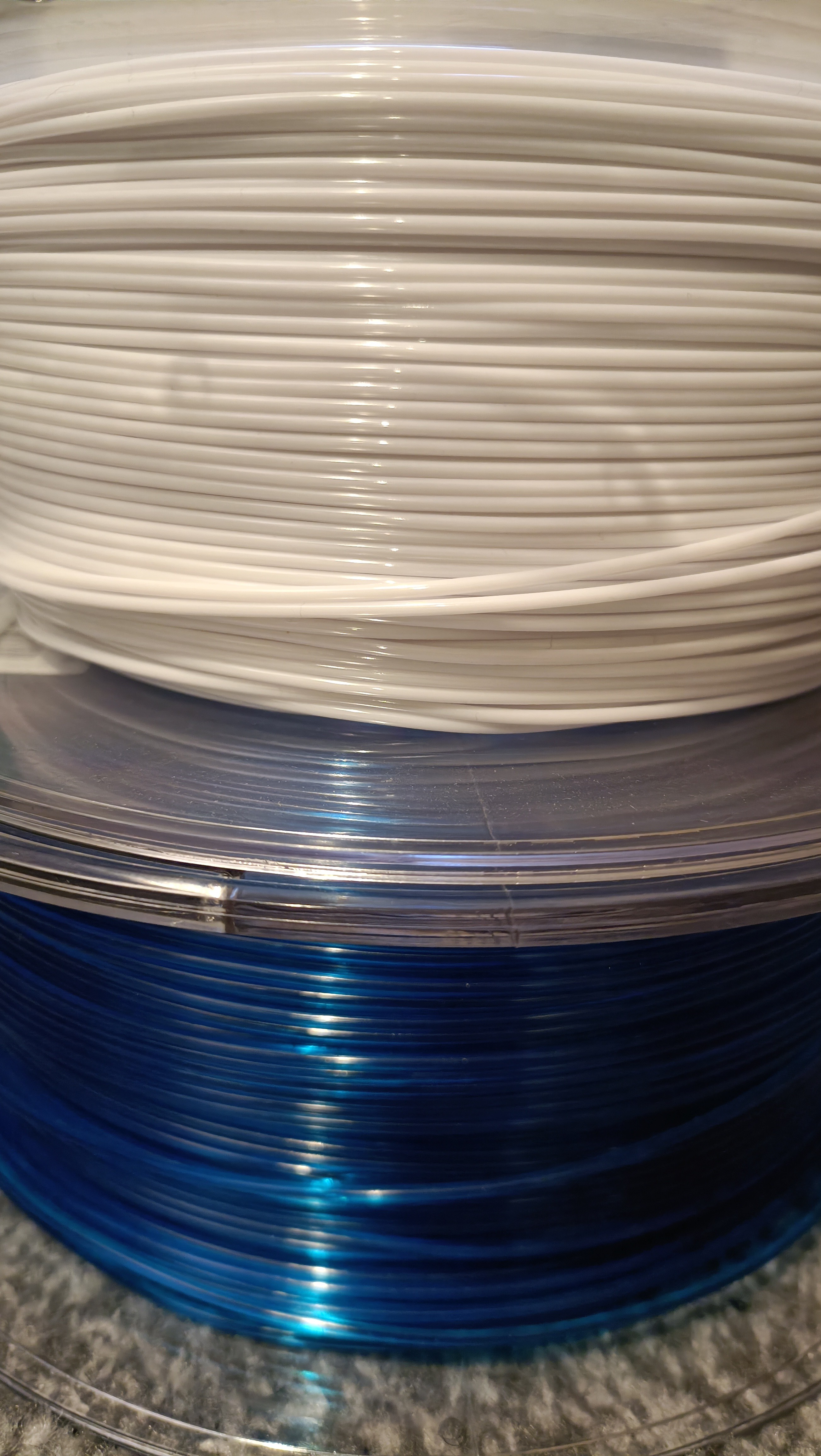
For reference, this is what the input filaments look like:
Anyway, at this point, my answer to the question "Does the solution pass or fail?" is actually "Partial Credit.". I can't say outright that the solution fails, because as long as it's good enough to put my other projects together, being able to mix, albeit slowly, is the solution actually working.
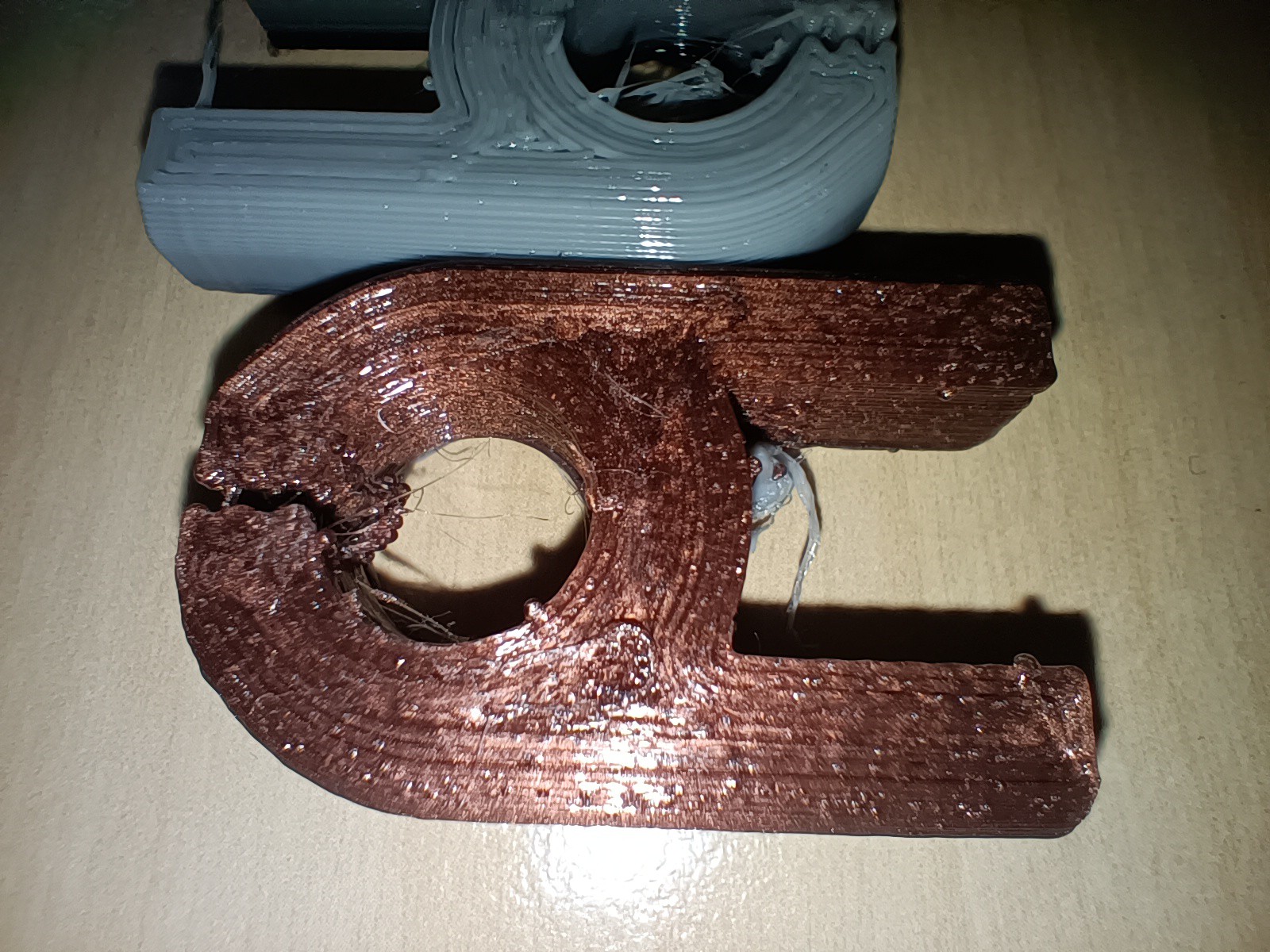
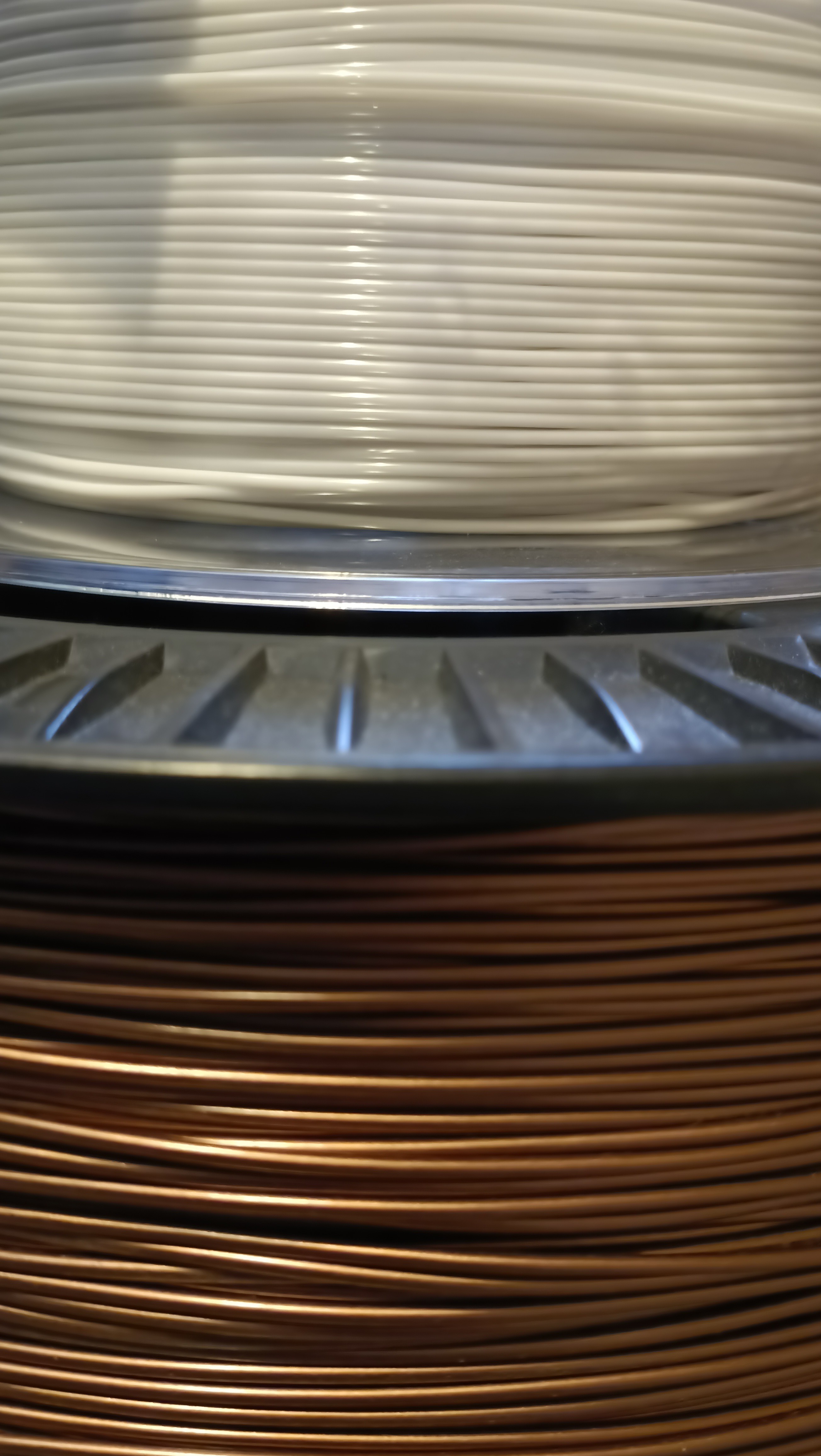
I decided to then move on with this 48mm/s speed to a new virtual filament of 50/50 copper/white, where the white encases the copper.
The filament looks redder in person. See one of the previous logs where I printed a clip with it.
I also decided to try channel 5 and 6 to see if it's potentially the minor channels that are bottlenecking my speeds. 5 and 6 have the longest uninterrupted major-channel diameter of 1.7mm, wheras I suspect that the dual minor channels are 1.05mm each.
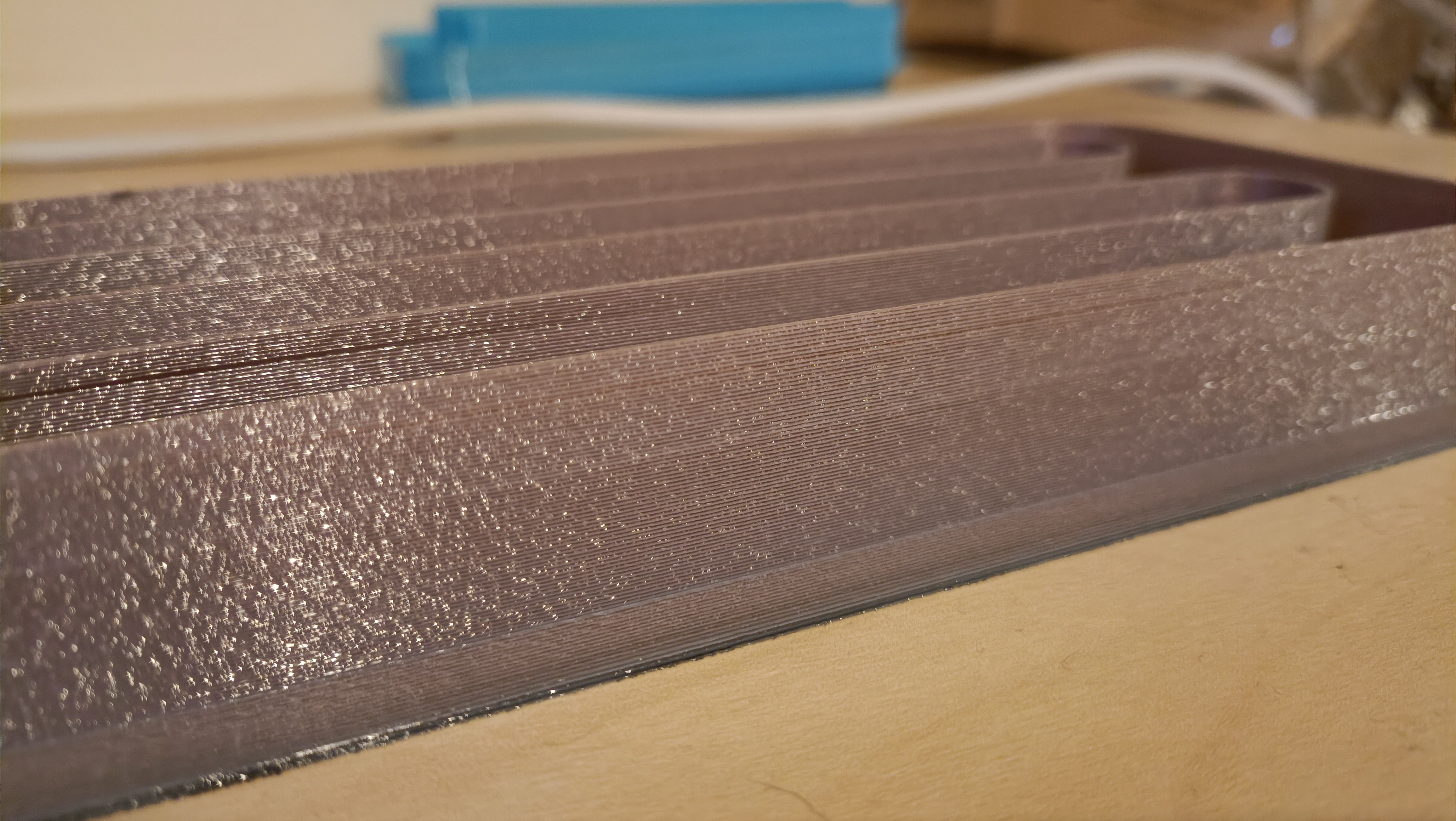
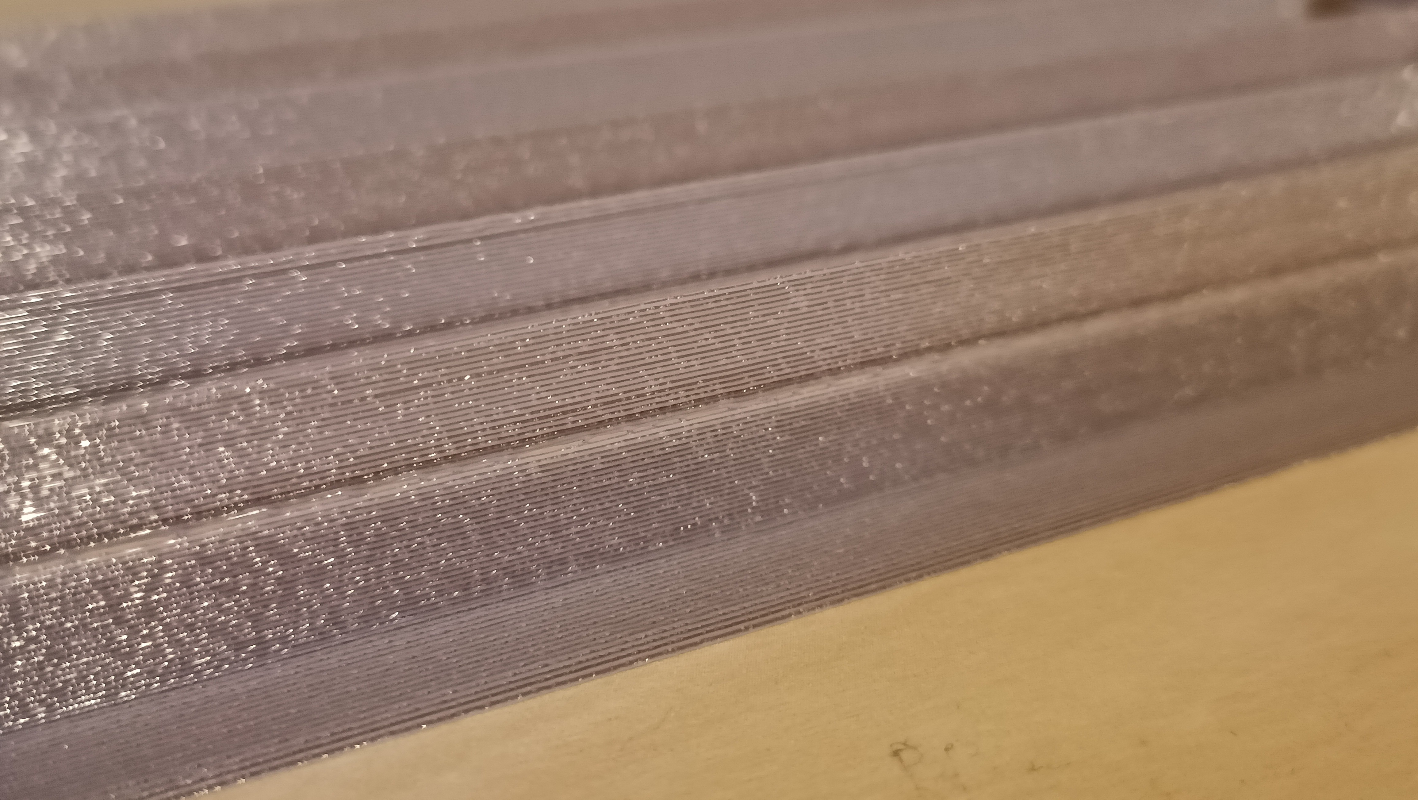
I started the print at 48mm/s and by the end of it, I was up 180mm/s speed! That corresponds to 86mm/s which I rounded up to 90mm/s for the print afterwards. Just like with the virtual light blue, this virtual light copper was a darker shade on the X axis, just even more noticeable this time. Both virtual filaments do look nice though.
I also had to increase the brim from 4mm to 10mm so that it didin't warp like the virtual light blue prints
With this test, it also confirms that I've been able to extrude through all 8 inputs. 🎉🎉
The next print was to confirm that I could print at 90mm/s, and it certainly looked like I could. 110% worked too but 120% didn't (see underextrusion gap) so I reverted to 110%:
As you can see, the zone when I reverted from 120% to 110% looked more consistent in X and Y. It was also lighter than the previous run:
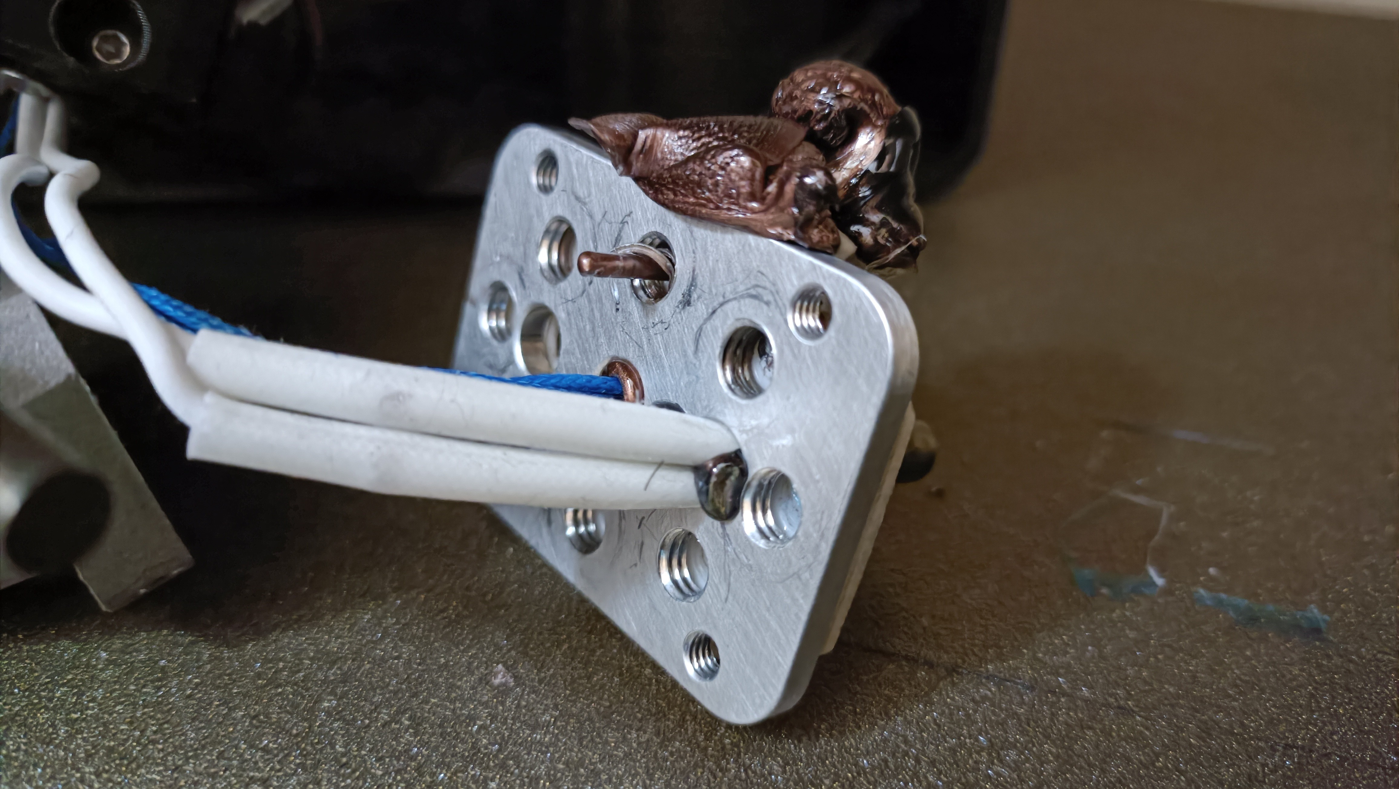
Secret super leak
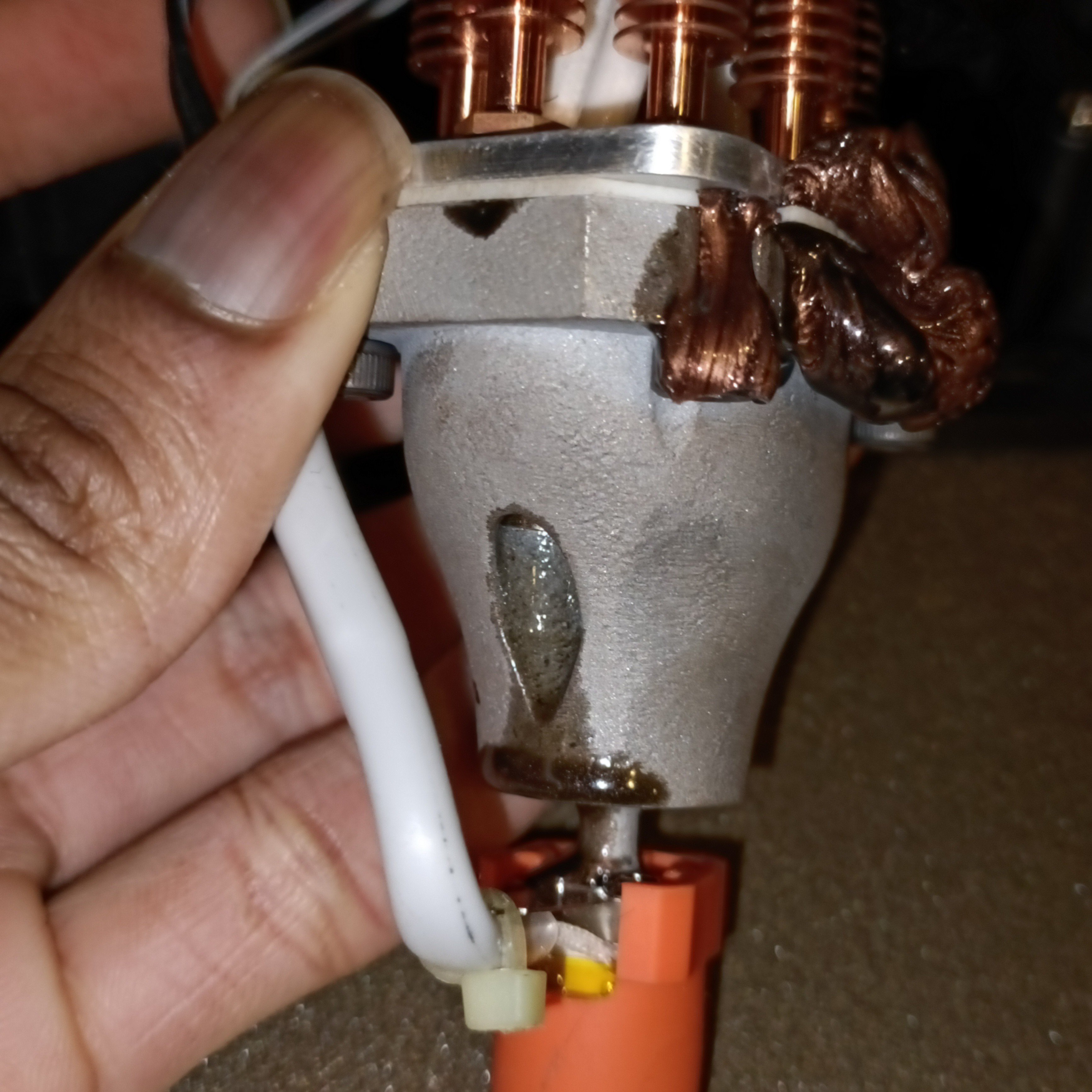
Now if you're wondering why the second run of Virtual Light Copper looks shorter than the first run, it's because I could smell a chemical-like odour and went to investigate. I shone a light though the front grill and everything seemed clean until I noticed that there was a black blob where the thermistor hole in the clamp plate is.
"Uh oh. What does the back look like?"
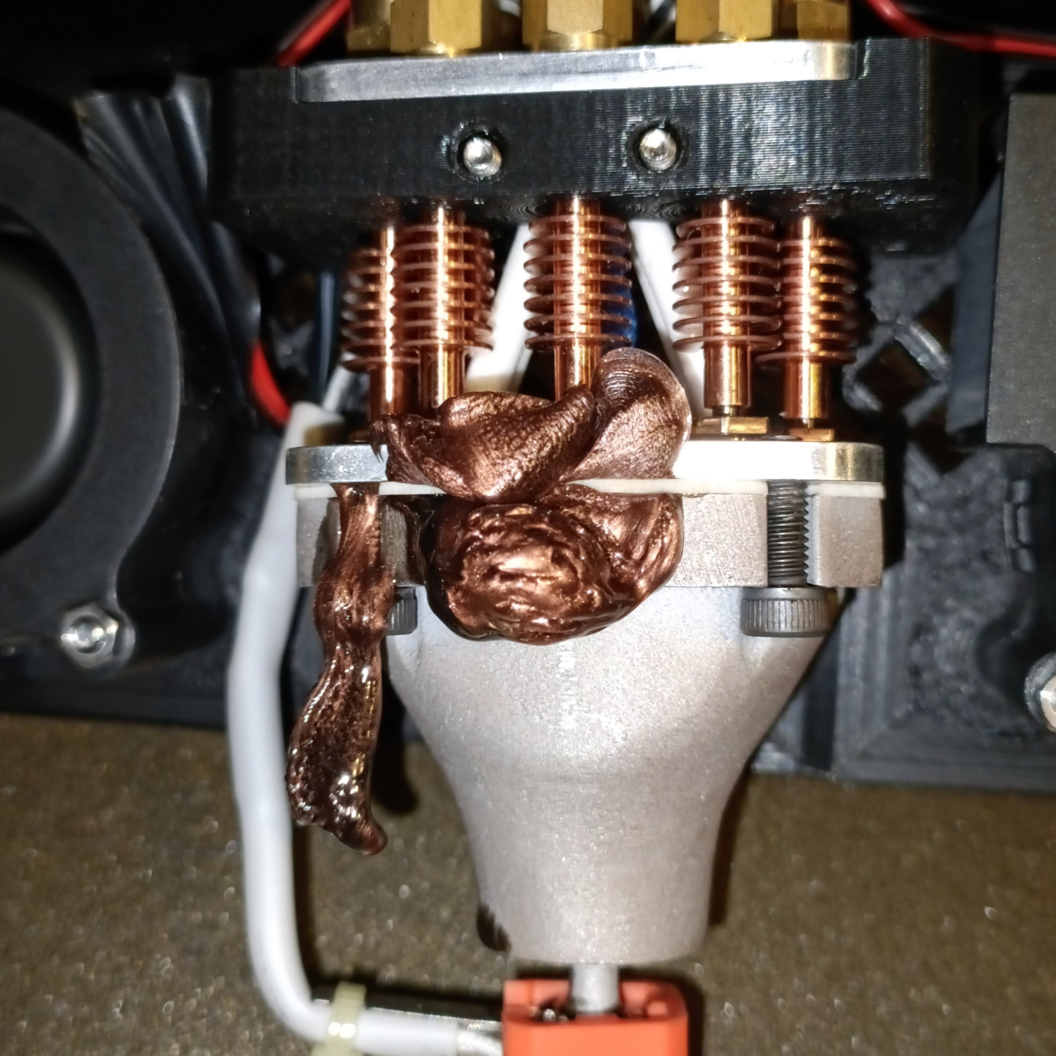
I squeeze to the back of the CR600S and I see two black+copper blobs coming out all sneakily through the boundaries between the PTFE gasket and the heatblock/clamp plate, and it was moving kind of like slow lava.
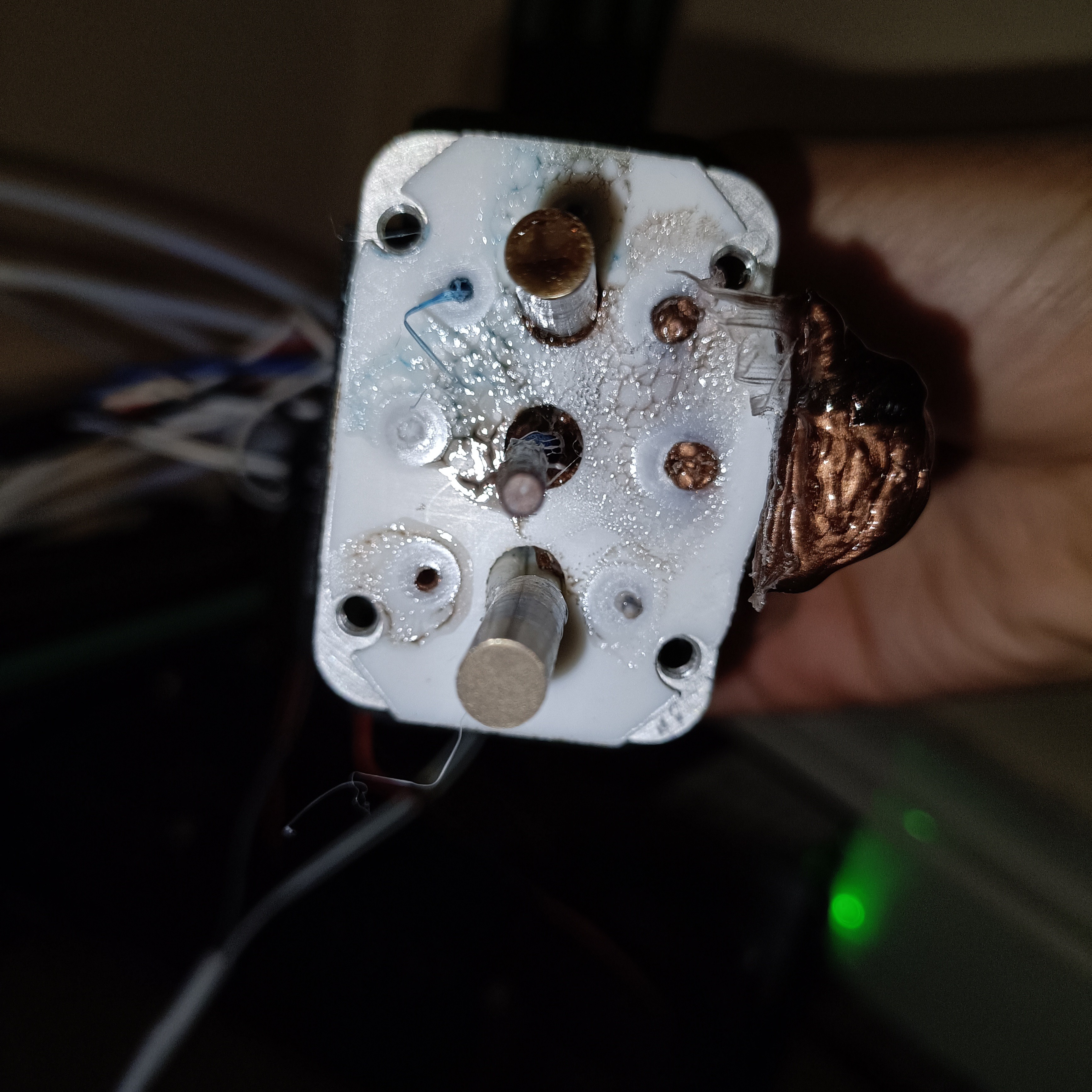
It was easy to take out all filament channels (except channel 3, which was stuck), then unscrew the bolts holding the clamp plate and the grubs holding the thermistors, then turn off the heaters, then slowly pull the heatsinks from the heatblock and finally unscrew the heatsinks.
I ordered the heatsinks from channel 1 to 8 in the below image. Surprisingly, even though channel 5 was the source of the leak, it's the one that is the cleanest; it cleanly separated from the copper PTFE.
One of the heater cartridges is also covered in black material.
Conclusions and future work
So, unfortunately, just like hitting a bomb in Fruit Ninja, this leaking means that:
The solution...
fails.
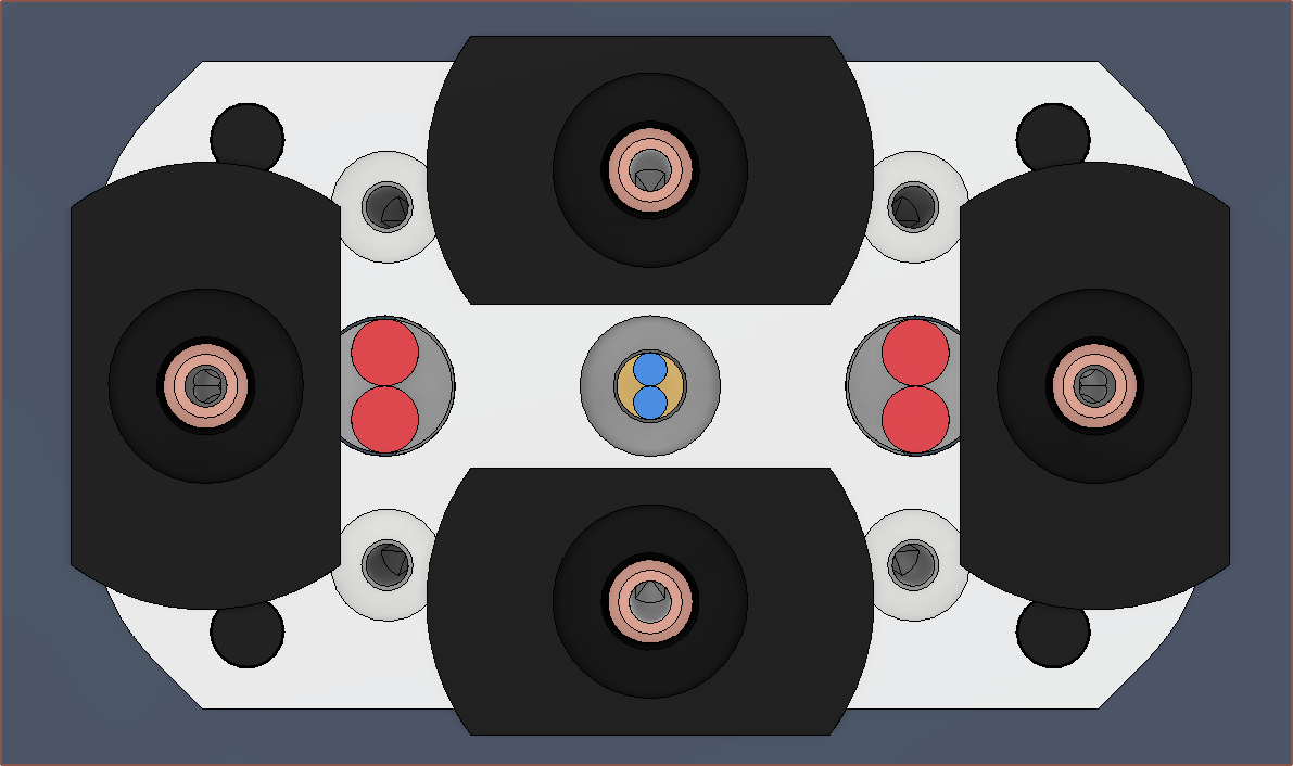
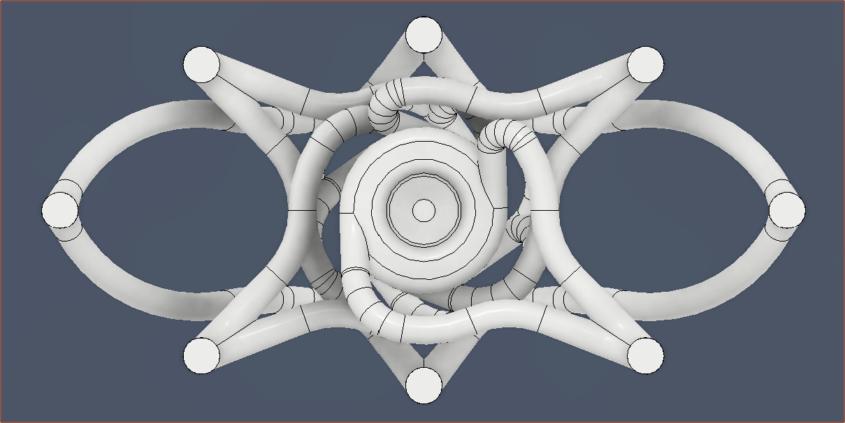
In the Coaxial8or R1 CAD file, I've increased the minor channels to 1.5mm, which should result in 1.3mm channels being fabricated. Now the cross sectional area of the two channels is 118% of 1.75mm filament instead of 77%. Below, I've highlighted the kinds of channels I'm talking about:
As for future work, I'm most likely going to have to pivot to a copper gasket:
0.5mm copper gasket and 8.5mm thick clamping block section on the heatblock, so as to ensure that the 12mm bolts are flush with the top of the clamp plate.
Heinz said that the copper deforms, and I'd imagine it'll be similar to the indents that the grub screws have made on the copper heatsinks.
This would likely help greatly with the day-to-day dealings of using an 8-channel 3D printer.
There's not enough pins on the Octopus Pro to be able to have a filament sensor for each input, but I hear that Marlin supports I2C communication and I've got some PCF8575 IO Expanders.
This expander has 16 inputs, which means that I could implement a "low filament" and "no filament" sensor, which I will explain below.
Redundant channels
I was thinking of a GCODE command to tell Marlin that it can switch to another channel if the filament runs out.
There needs to be a way to differentiate that there isn't any filament (or plugging wire) into the hotend, so that the heatbreaks aren't clogged with material flowing into the wrong direction, and just that there isn't enough material to continue printing with it.
Thus, the "no filament" sensor, mounted as close to the extruder inputs as possible, and a "low filament" sensor, which can be mounted a bit further away, is required.
Unlike a switching extruder, mixing extruders can feed multiple channels in at once, meaning that there should also be a feature that actually just uses all redundant channels at once to increase flow rate.
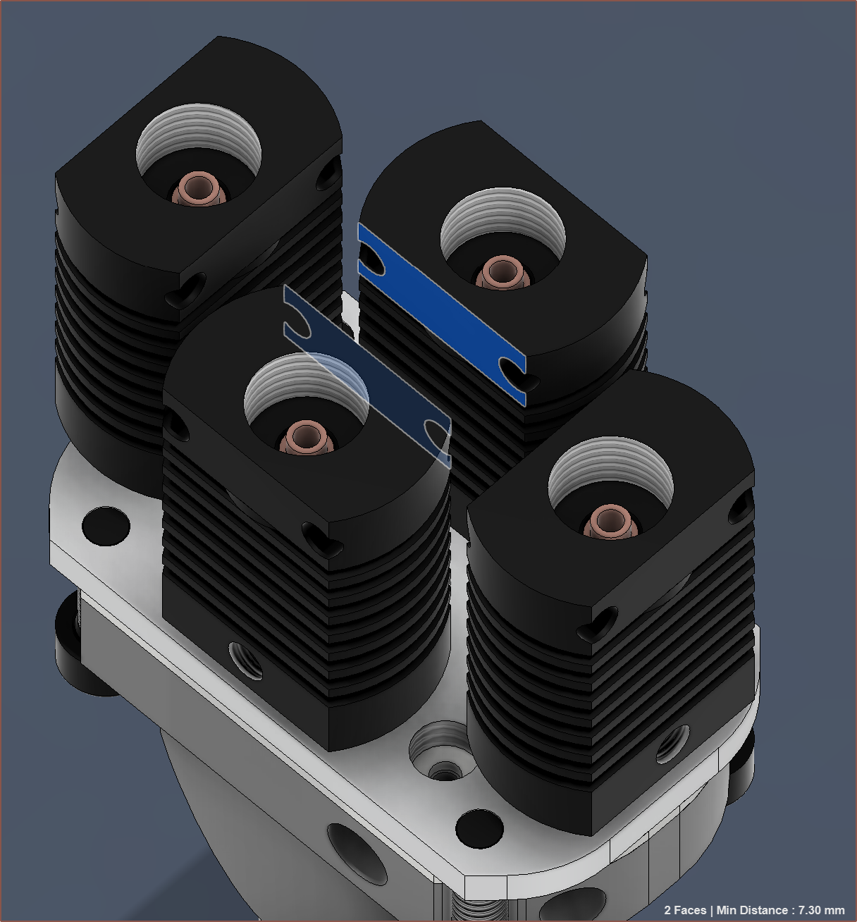
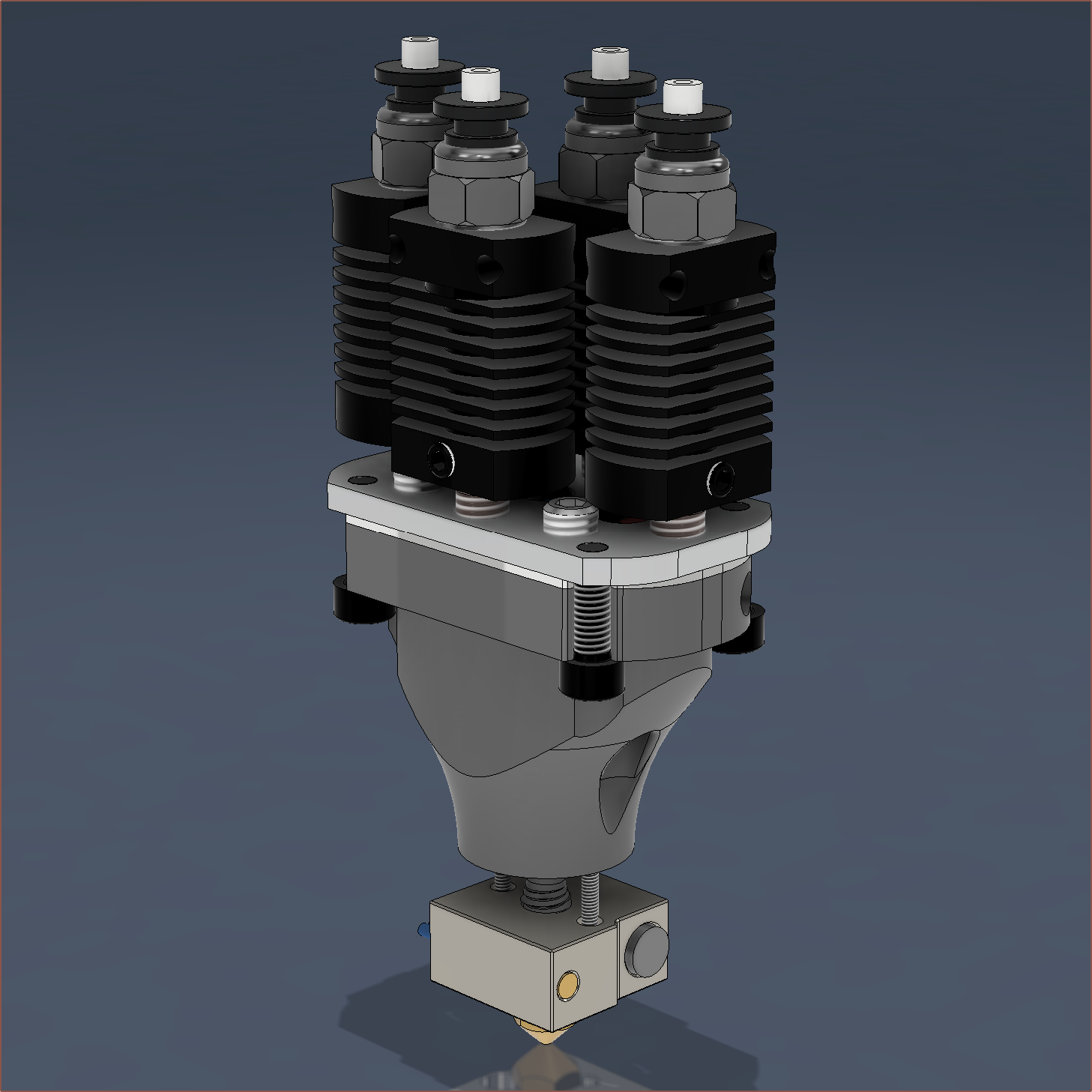
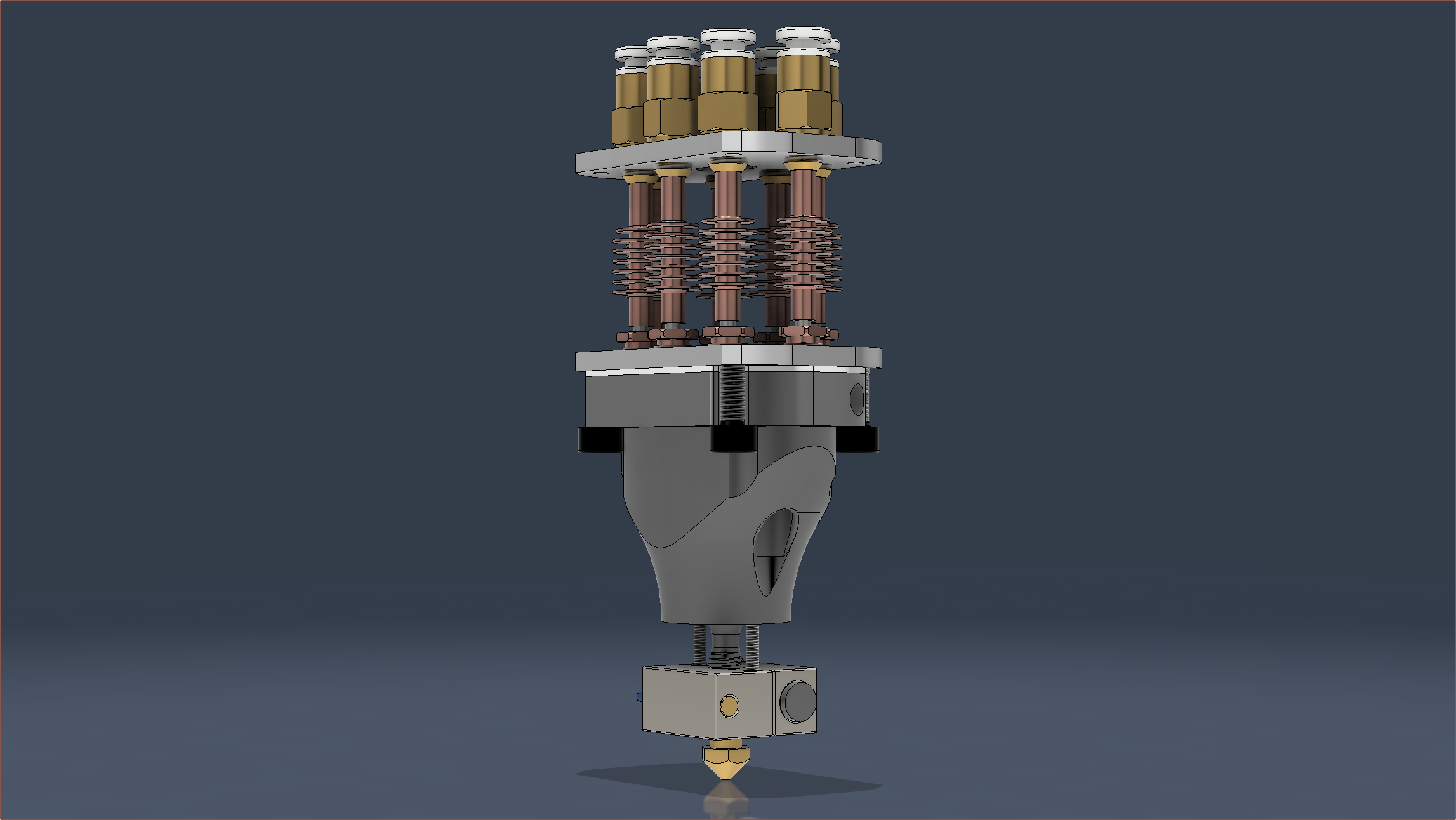
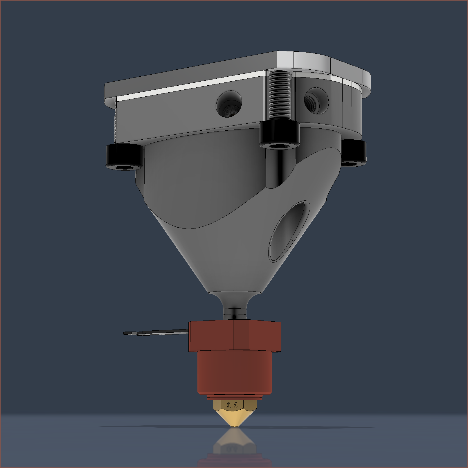
Reducing the height by 2mm and the volume by ~2500mm^3, I've refreshed the Coaxial8or R1 and swapped out the old nozzle heatblock for a CHC (that I tweaked from the CHC Pro CAD I already have).
When designing the internal channels, I decided to play it safe and have every input the same. However, I'm now thinking that channel 8 could be like the image below without any drawbacks. If anything, it might help increase flow for that channel.
Also notice how the cartridge heater holes now go straight through the heatblock like the machined coaxial heatblocks designed in the past.
I started today by using my FysetC ceramic screwdriver to turn the voltage of my adjustable power supply down to 24.2V and then installing into the system.
I could play the Studiopolis theme tune to this look.
Unfortunately, the current display cannot be trusted, as it only displays 0.00 unless there is a heating load applied, and even then, it only showed a peak of 7.5A that drops to 5.6A during main heating. Heating the c8or was about 3A, which equates to 72W or half of what it should be drawing. Activated motors don't seem to move the needle at all.
The power supply otherwise seems fine, keeping a solid 24.0 - 24.3V under all loads.
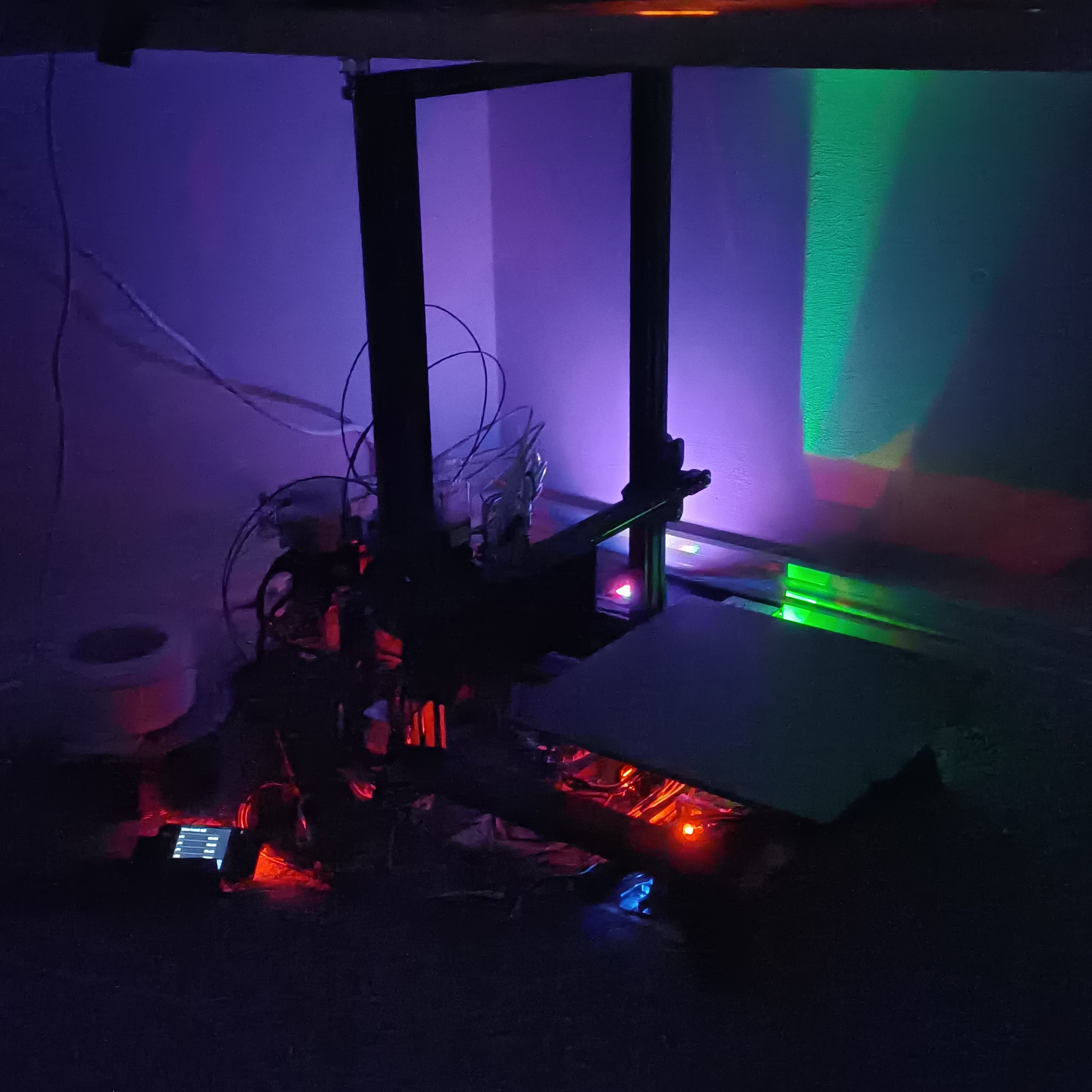
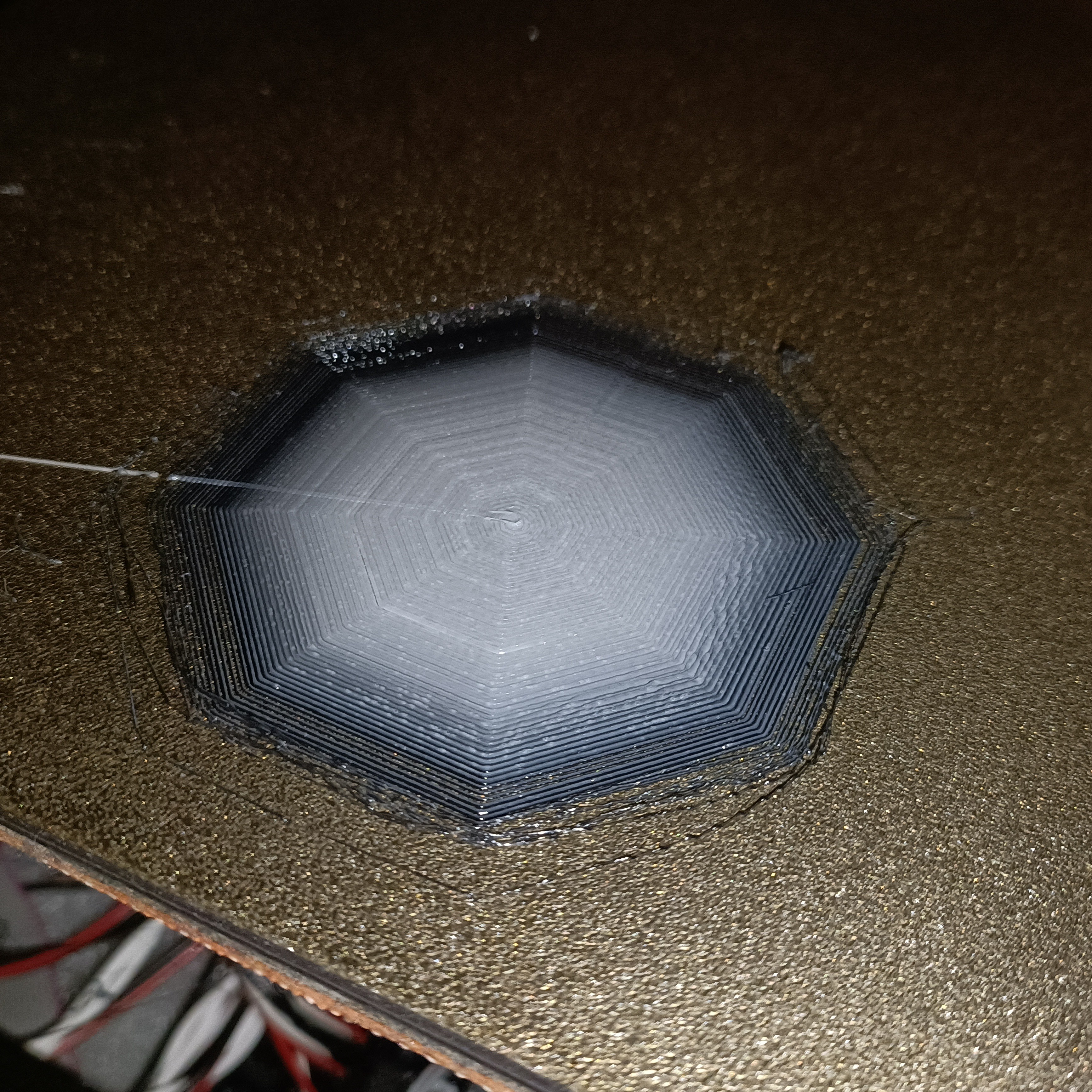
Coaxial8or Priming
I wanted to do a flow calibration, but I wasn't getting much extrusion so I thought that I'd print a flat octogon to make sure the internal cavities of the heatblock are filled. I used E0 for this, which has white installed.
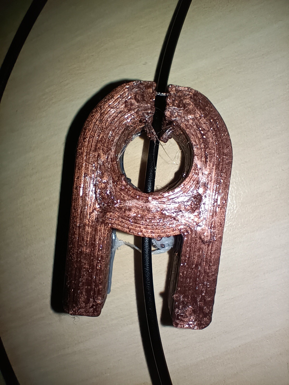
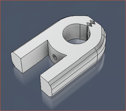
Clip for M592 Testing
The night before, I had found out about M592, a feature implemented into Marlin to account for the reduced amount of material fed into the hotend at higher extruder speeds. This is because M593 is ZV input shaping. M493 Fixed Time Motion has more algorithms, but does not support a mixing extruder.
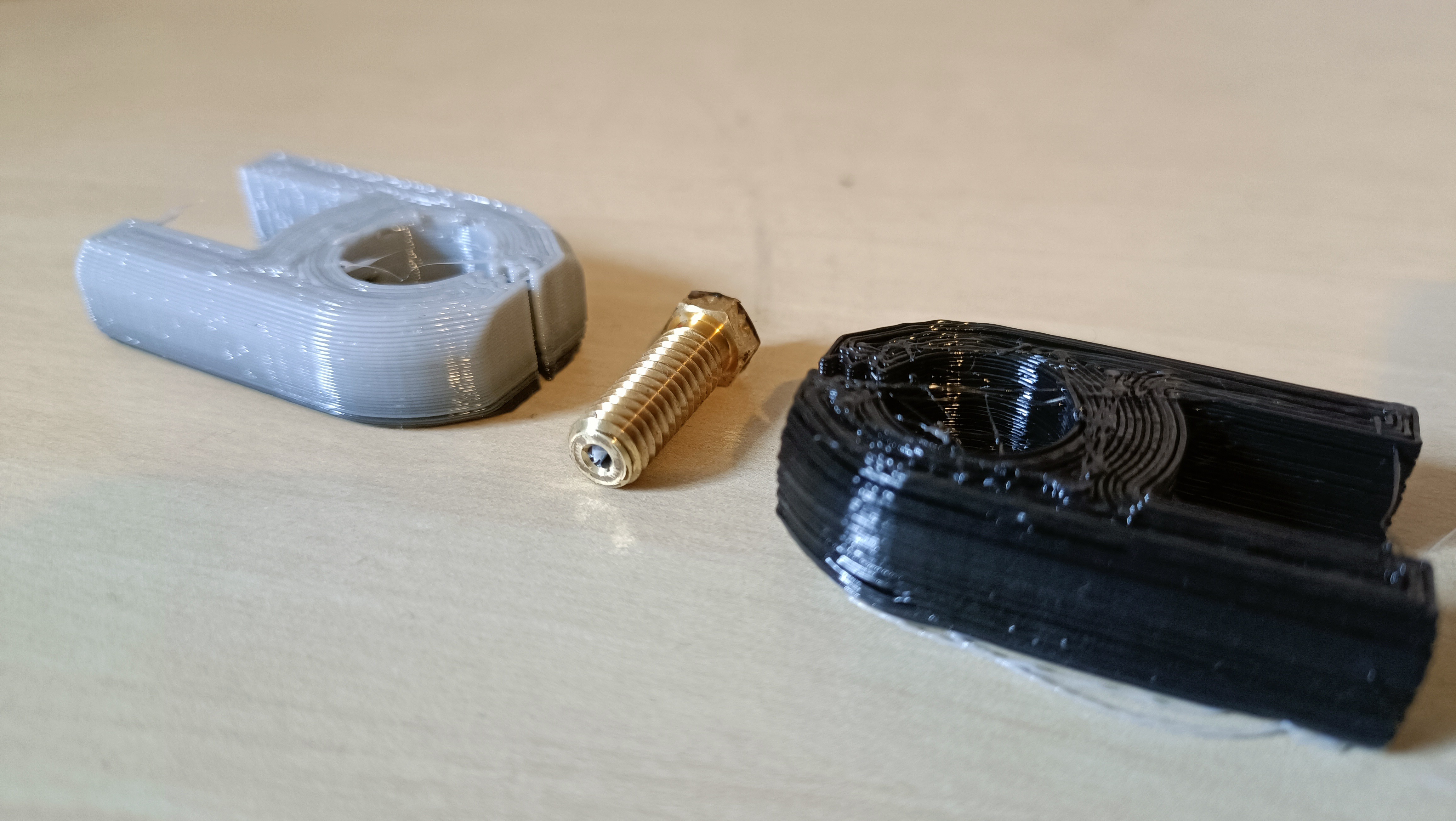
I had an idea that I could use a clip of some sort to place on the filament and then move it so that it's 50mm away from the extruder entrance and then extrude to get the values I needed, and I wondered where I was going to get such a clip. Then I remembered that this is what 3D printers are for, so I modelled one in Fusion.
Printing
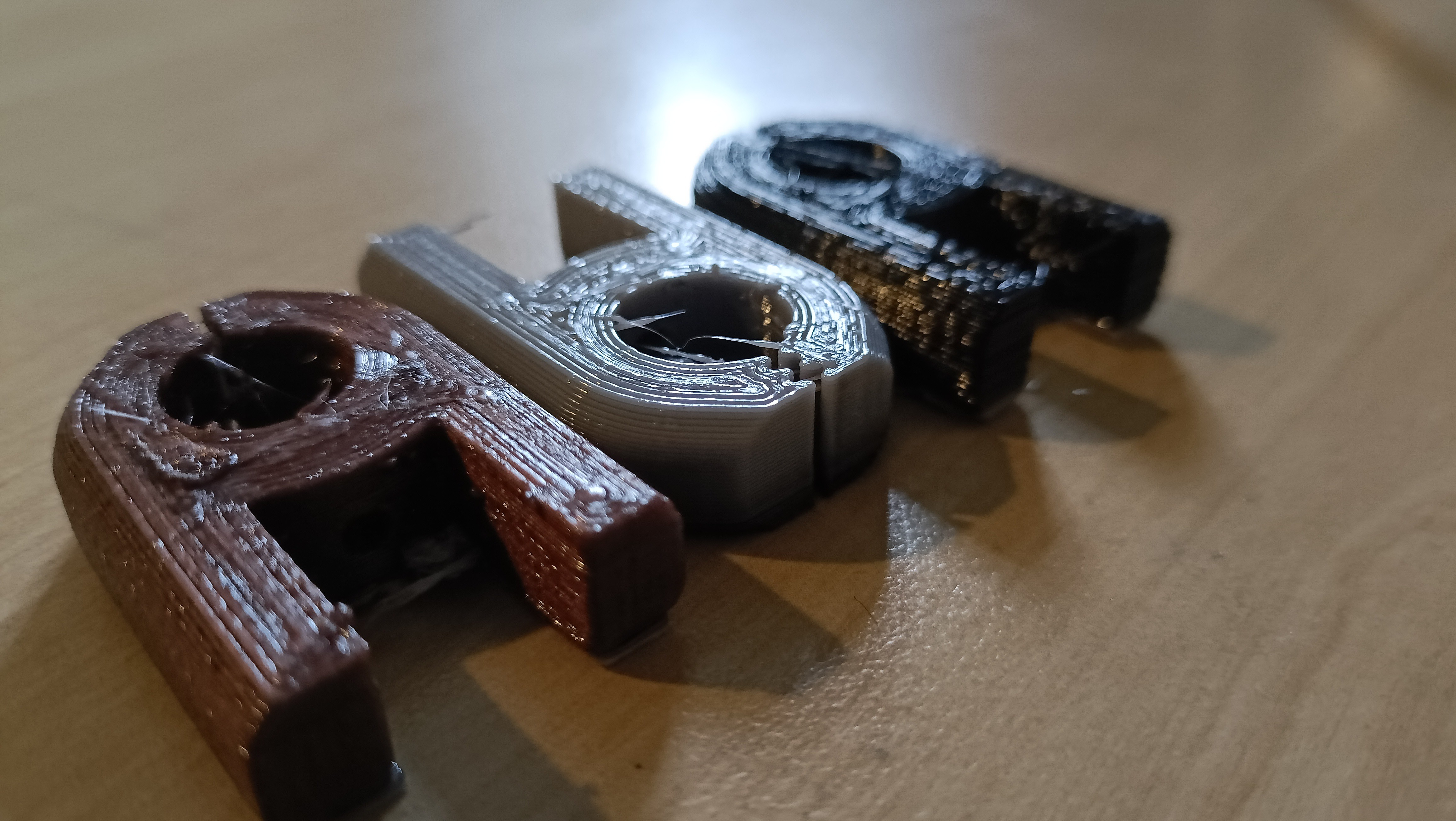
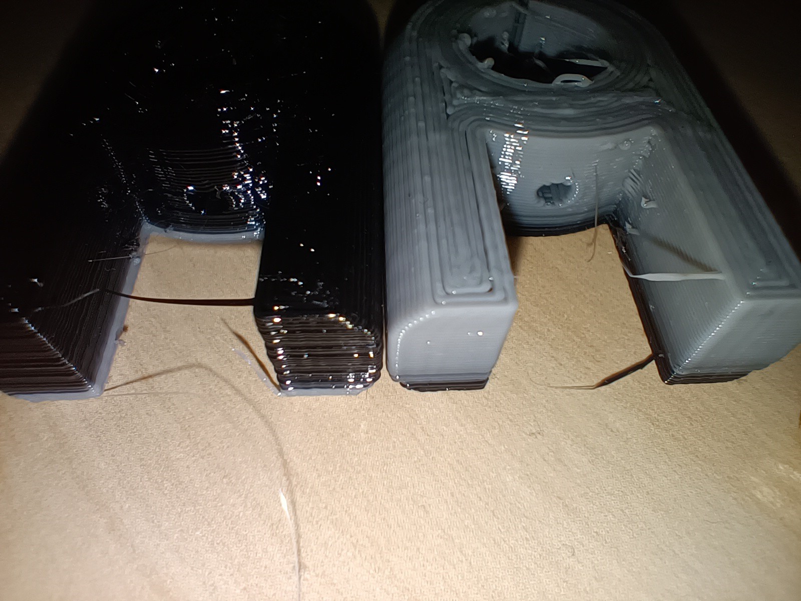
All 3 prints that I did today.
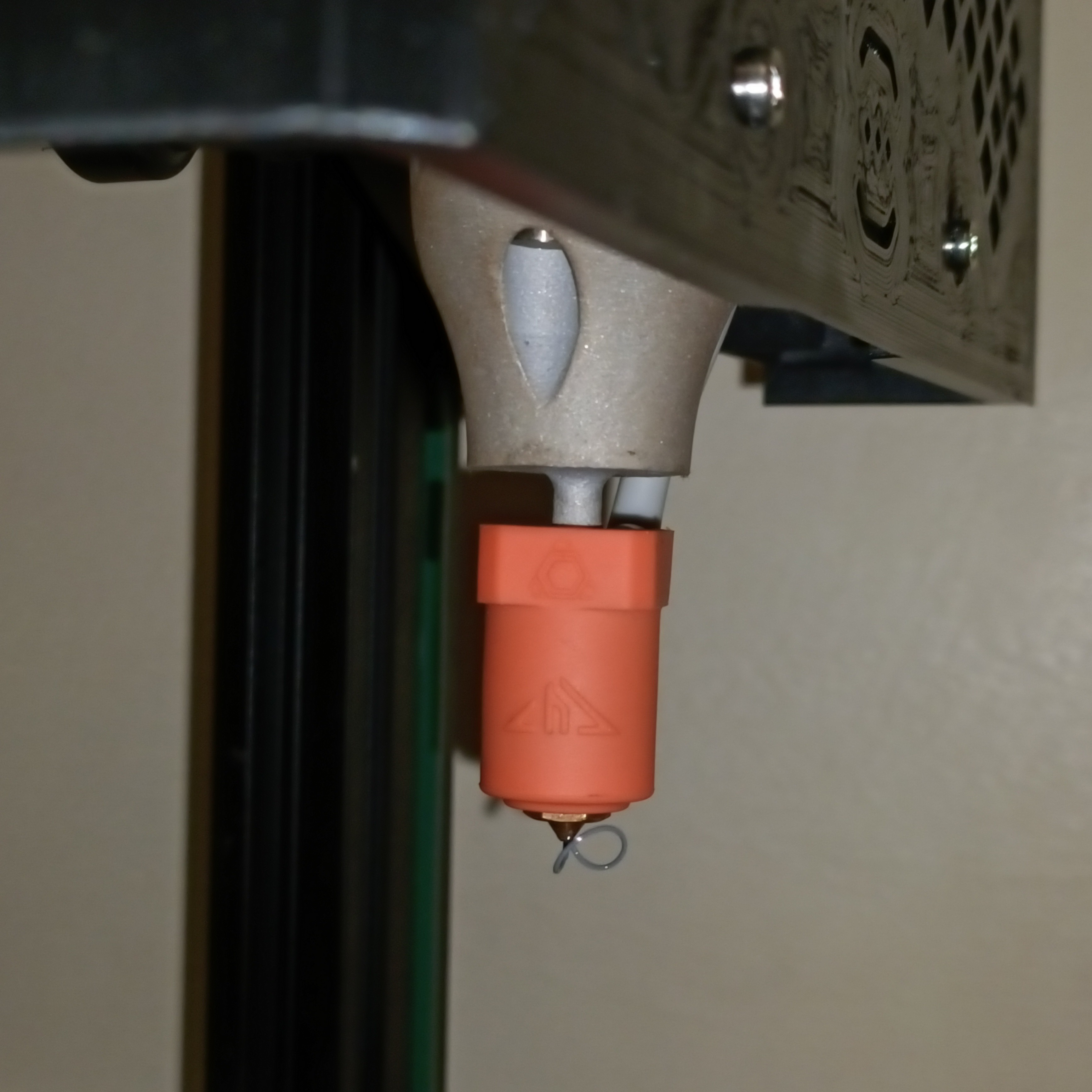
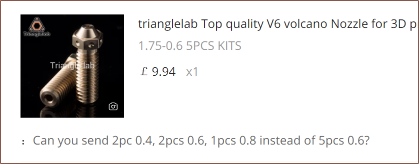
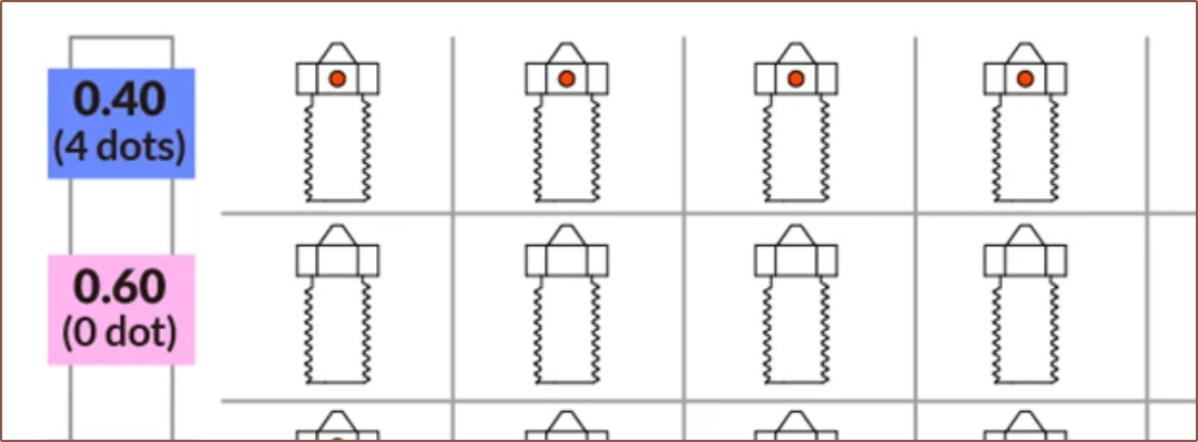
I decided that I was going to print the clip as a test print, and do so in black to see the time for a colour transition. I was getting extruder skipped steps, but the print did complete. From the whispy ooze, I measured 0.43mm and suspected that the volcano nozzle installed wasn't my go-to 0.6mm nozzle, but instead 0.4mm. Thus, I started a print in white with 0.4mm settings and confirmed my suspicions during the print.
I indeed have 4 dots on the 2 nozzles I have.Both prints looked very shiny, so I assume the PETG was thoroughly melted. It seems that PrusaSlicer was set to 2mm retractions, which sounds fine for all-metal heatbreaks, so I'm going to try a temperature tower first before tweaking retraction settings. As you might be able to notice, the white filament essentially plateus at a light-grey colour. Perhaps the ideal filament order is in reverse to what I hypothesised.This is when I decided to look for leaks. I peeked through the grill and the back of the cover and saw no leaks peeking out anywhere. The mysterious synthetic odour I forgot to mention in the previous log was also much lower to the point where I forgot about it; I assume it's just like getting any new appliance and heating it up for the first time. I was also able to loosen the nozzle when cold, which is another good sign that there are no leaks. Lastly, the face at which the coaxial8or meets the nozzle still looks clean, so I assume that the leaking issue has been sufficiently addressed.
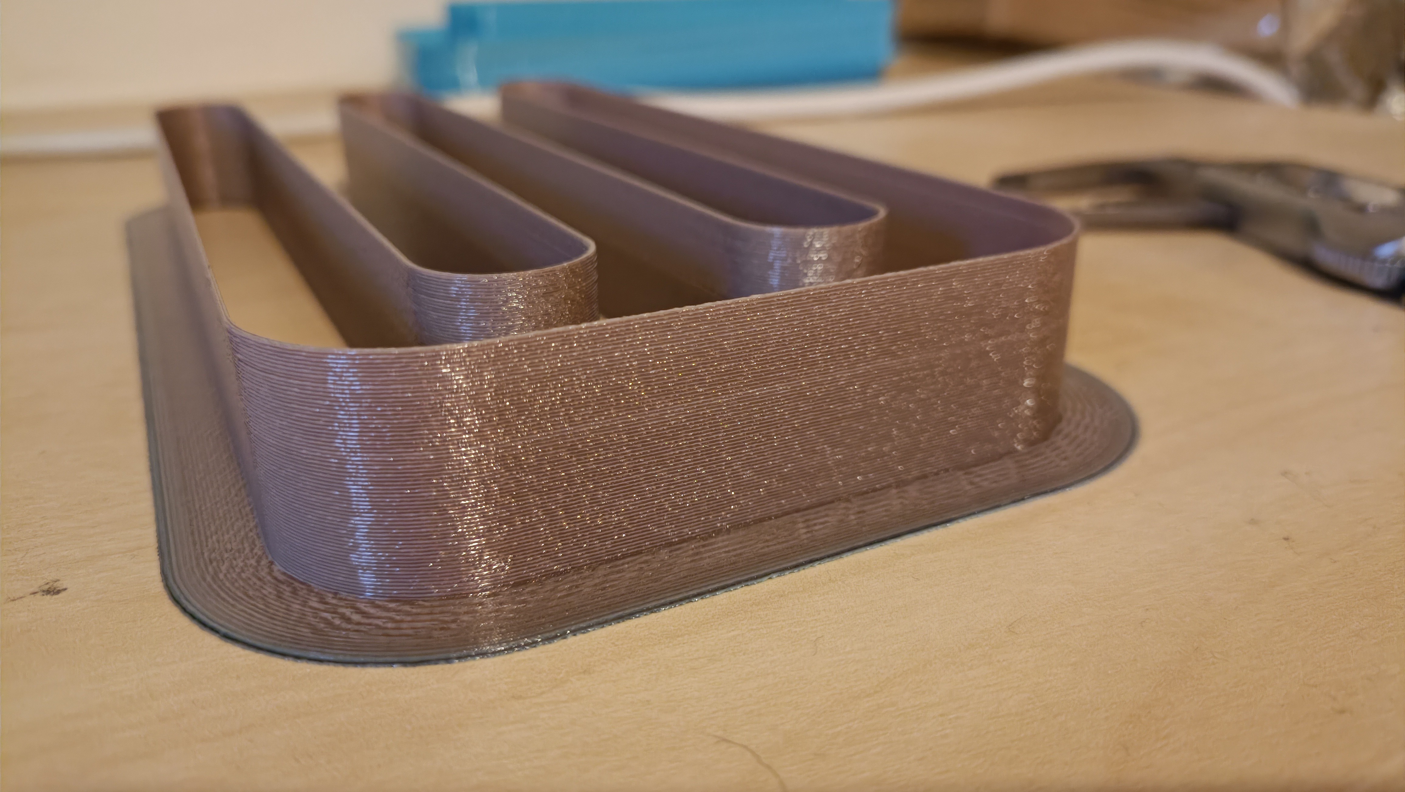
I moved on to a 3rd material: Copper PETG. I bought it around this time in 2018 and this is the first print I've ever done using it because of it's unweildly 30cm diameter spool (filament spools are usually 21cm). Since I'm only doing short test prints and dont have any spool holders, I've just had the filament on the floor and I spin out some slack length. I also decided to switch to my plated nozzle that I planned to install in the CR600S sometime in late 2019, and can confirm that I can do a 1-handed nozzle change.
The material actually looks very nice -- much nicer than implied on the spool -- but I can't tell if it's wet or if that bumpy sparkle look is the intended look. The purge transition went light-grey, black, copper after perhaps 5 layers. I believe I started with the c8or at 218C but dropped it to 212C when it seemed that the extruders could handle it.
To my delight, the print actually does work for its intended purpose -- I thought PETG would be too slippery but decided to give it a go anyway.
I'm also getting surprisingly good dimensional accuracy for my first test prints. Both the white and copper prints measure 11.99 in the spacing that is supposed to be 12.00mm, as well as 7.05mm for the arms that should be 7.00mm. The inner circle is 6.92mm and the thickness between the inside and outside is 6.88mm when it should both be 7.00mm. I think I can say that I've found the perfect E-steps/mm number of 1675 for 64 microstepping (which translates to 209.375 for the 8 microstep mode I've configured the CR600S for).
Conclusions and Future Work
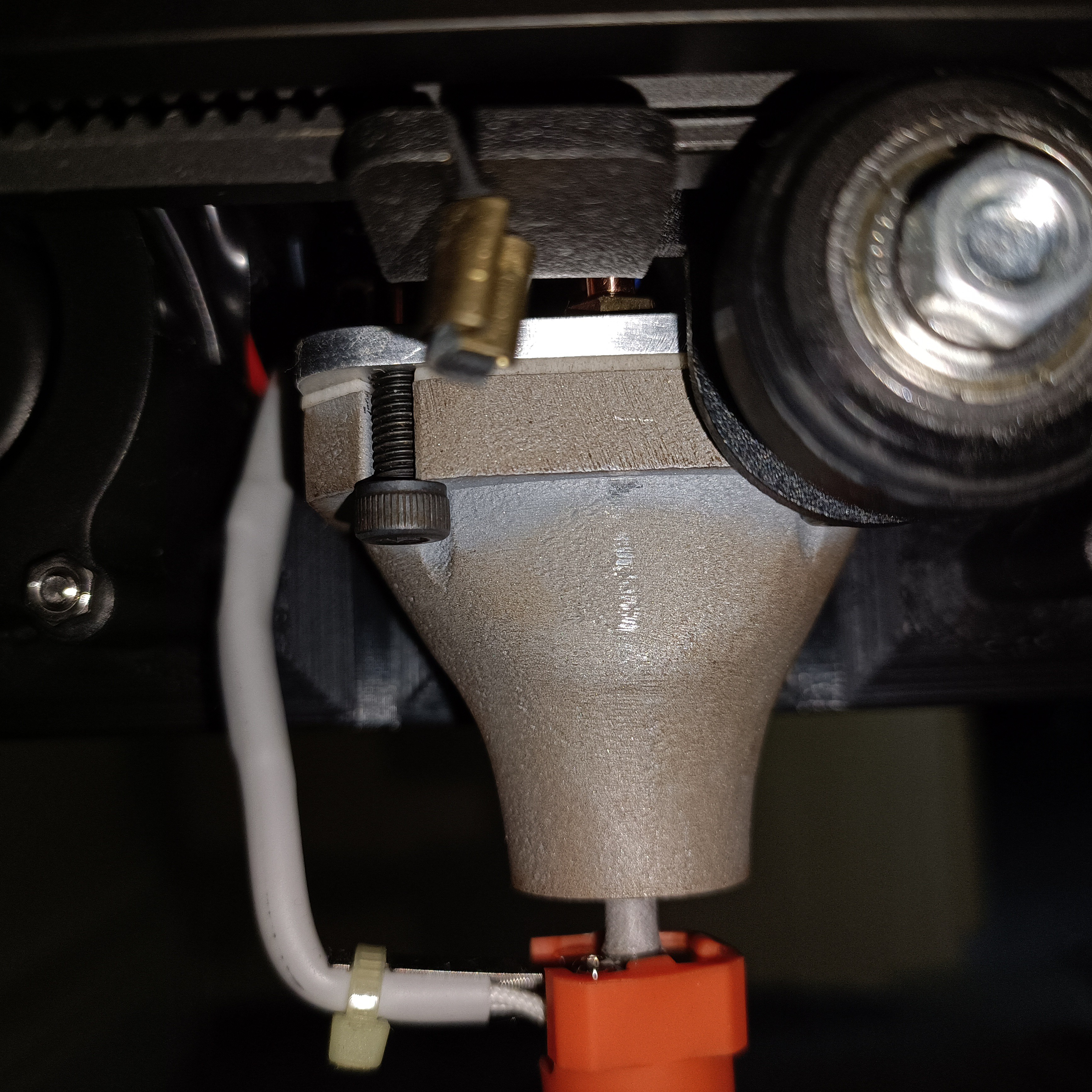
Speaking of copper, I've just had a look to see if the CHC Pro wire is touching (and melting on) the c8or and the heatblock is looking like it's been lightly seasoned with copper, interestingly enough:
The cable seems fine though.
It does seem that the M2s could be removed from the updated design and favouring the CHC-style hotends.
I'm looking into running a temperature tower tomorrow and hopefully I can move towards getting 2 or more colours in the same print.
For some reason, the PSU is fluctuating between 23.8 - 24.2V periodically and the system is just sitting idle.
I wasn't able to repeat the cold-remove nozzle with the plated one, implying that the seal wasn't as good as the first time. I heated it to 100C just to tighten the nozzle more and it turned by a few degrees. Heated to 150C and didn't move so I assume 100C is good enough.
So far, it's been shown that 37.5% of the hotend can flow, at least. For dimond nozzle users, this would be 100%, and through reading some of the posts of people that have them, leaking was still a large issue. I think the PTFE gasket is a good solution as it better ensures a seal than getting the end of a tube flat and flush, and provides a nylock-nut / Loctite effect for the heatsinks. I feel like it also allows a higher tolerance to thread tightness variability.
This trial was also to test to see if I could print in one colour and then switch to another colour and not have a clog, and this initial testing shows that there is potential. PLA would be the real test for this, though.
[April 4] I've tested flow in another 3 inputs, and I'm not liking how the flow seems best when the Coaxial8or approaches regular PETG printing temperatures. The best result on the temperature tower I've printed today was 224C for both the heatblock and nozzle,
C8or: 224C for all. Nozzle: Starts at 236 on the bottom and drops to 212 at the top. No idea why the 218C level looks crushed like that.
Part of the reason I decided to use a PTFE gasket was because I didn't expect to need to go over 200C, but that doesn't seem to be the case and I'm not liking the idea of potential offgassing that PTFE might do over 200C with such a relatively large amount in contact with the heatblock. I've heard from @heinz that Cetus used a copper gasket in their Cetus2 hotend, so I might look into that.
Initial stringing so far seems expectable for PETG through a 0.6mm nozzle:
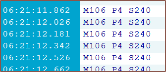
Currently testing 4mm retraction at 120mm/s and 218/224C for c8or/nozzle. Travel moves are 240mm/s.
I feel that the main issue to addresss is why the extrusion force feels so high. It might have something to do with the standard bowden tubes as there's a notable amount of springiness to the input channels when the hotend is cool. At the same time, even in channel 7 (E6), my white PETG is only a light grey.
So, instead of the "move fast and break things" approach that Me In January did, I took a more cautionary approach and did some dry-runs first. It's a good thing I did, because I caught issues like the G3 crash ahead of time and was able to increase my Y current to 900mA because it was skipping steps.
After a successful test-run of everything running except fillament through the extruders, I installed filament into them. The large gear on the DDEs are useful because I can see / feel if the filament has actually gone inside or if it caught on the bowdens. Seemed that the PETG understandably went through the system a lot easier with the c8or set to 224 degrees instead of the 188 I had originally set and used in the dryrun.
After getting the skin on my thumbs iirritated and peeling from all the high-torque scrolling of the gear, I used my handy M165 R to set the mix to A1 B1 and see that it was set correctly before then extruding perhaps 200mm of filament in. While this was happening, I took a flashlight to see if there were any obvious leaks and I didn't see any, which is a good sign at least.
Whilst wondering if this filament was actually getting anywhere, I saw a whisp come out of the nozzle and ghasped.
There's filament, and it's grey! I'm only extruding in White and Black PETG. Thus I changed the start-gcode to heat the Coaxial8or to 224C and pressed print.
Now this is where all the goodness ends, because my Z offset was wrong and so I was scraping on the bed. Whilst trying to increase the babysteps, the printer just turned off. This wasn't like the G3 crash where it would restart after a bit, because the PSU LED was off too! Whilst turning the printer off and on again brought power back and I was able to re-tram the bed, the power cut perhaps 1 second into the homing and heating procedure.
So I did the calculations and when I add:
140W Coaxial8or
115W CHC Pro
24V extruders with currents (in amps)
X: 0.6
Y: 0.9
Z: 0.6
E0-7: 0.45 x 8 = 3.6
...I get 392W. Considering everything else would be probably another 15W, I've likely exceeded the overcurrent protection of my £6 PSU.
Look, I bought it because it was small, looked nice, was silent and would arrive fast (and £6 for all that sounded amazing). When I did the original calculations, I was getting maybe 80% utilisation, likely because of the lower initial motor current estimates of 0.6 for Y and 0.3 for each E.
This kinda makes a bit of sense because, during tests, I could hear the fans drop in frequency and the multimeter tested a shaky 20V value, most likely because the heaters are only toggled at a relatively low 7Hz from what I've heard in the Marlin discord.
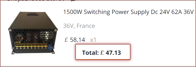
I've still got my £60 (that I bought on sale for £11 off), 0 - 36V, 1.5KW PSU beside me so I guess I can install that, but first I need to lower the voltage to 24V or else I'll fry everything.
Just not a fan that the voltage and current adjustment are two tiny trimpots.
Surely this won't be the third power supply this project eats up. The good thing about this PSU is that it's got a current and voltage reading so I'd be able to spec the next one accordingly.
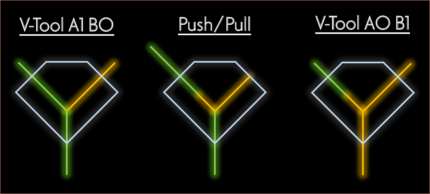
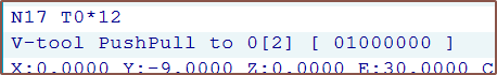
I've spent the past week implementing this feature I call push/pull toolchange.
It started when @heinz posted his findings with the Cetus2 nozzle and its strategy for fast toolchanges:
The shownotes of implementation went something like this:
Day 1
Write initial pseudocode
Day 2
Look inside tool_change(...)
Write config modifications, looking at SWITCHING_TOOLHEAD for naming conventions
Write more detailed pseudocode
Try and understand what COLOR_A_MASK means
Day 3
Look at how the extruder directions are applied (and ask if there's any specific thing I'm supposed to do so that I don't break everything, since this is outside the mixing-related code.
Look up what do { } while(0) does, and it seems to make sure if-blocks don't break things.
Day 4
Find out there's something called MIXER_AUTORETRACT_TOOL
Understand a few other functions in mixing.h
Create a pushpull type
Day 5
Turn off VSCode Cpp formatting so that it doesn't mess with the formatting that's already present
discover "mix" and related functions, and enable them for push/pull
Write initial implementation for pushpull in the mixing.h side of things, such as creating MIXER_PUSHPULL_TOOL instead of a colour in the pushpull type.
Day 6 (today)
Find out that there are bit-mask macros and use them to tidy up my code.
Try, fail, try some more to create the new E_APPLY_DIR macro.
Change get_extruder_bits(...) to e_dir(...), where the former gave the thing that asked for it the entire 8 bits wheras the latter is a boolean on if that specific extruder is inverted or not. This made the MIXER_STEPPER_LOOP easier.
Allow pushpull to use the too_cold(...) function already in toolchange.cpp
Get more errors that stem from how I implemented the E_APPLY_DIR macro, as well as Mixer::pushpull
Finally get the E_APPLY_DIR macro to work by needing essentially a do { do { ... }while(0) }while(0)
Add a definition of pushpull_t Mixer::pushpull into mixing.c
Marlin compiles finally
Fix errors when optionals in config.h are disabled
Improve too-cold error message by adding an additional context message
Everything seems to work except I'm not getting any directions
Test to see that my bits are being set correctly
Find out that I need to apply the stepper directions, and I can't do that from mixing.h
Split the code so that the logic responsible for extruding was in toolchange.cpp.
Extruders work but there are a few quickly-squashed bugs.
I just got this quick idea to see if classic CR-10-style heatsinks would fit such that it can still be easily mounted onto a CR-10 / Ender3 whilst using the 2x M3 bolt mounting points (and not having to print a holder). This is because I was thinking of the Coaxial8or from a finance perspective.
6 inputs?
The main question I expect to get is "Why 8 and not 6 inputs?" and one of the reasons is that, financially speaking, the difference is about a £30 upgrade. The cheapest option to run a 9-axis Marlin configuration is an MKS Monster8 + BTT EXP MOT and it's probably cheaper to buy 10pcs couplers than 6 individual ones, thus the only difference in price is 2 of the following:
Nema 17
Extruder
Stepper driver
Dragon heatbreak
Additionally, there exists "flat point" grub screws. 10pcs M6x6 only costs £2.75. I'm assuming that if the heatblock is first filled with cleaning filament, the unused channels stay inert and don't clog, allowing for the possibility to upgrade to the full 8 inputs in the future.
For the aluminium print itself, the auto-quote is $46 and I doubt the ~5mm shavings in the X and Z bounding box would account for much, since it seems that the minimum PCBWay cost is around $38-40.
4 inputs?
The financials (and ease of set-up) for 4 input make more sense, as the heatsinks are cheaper, all the drivers fit on a single board and could even be a pseudo-drop-in replacement for anyone using a Zonestar 4-in 3D printer / Prusa MMU1.
A 2x M3x35 bolts would be needed to mount the hotend, and a 7mm spacer would need to be bought or printed:
The result is what I'm currently going to call the Coaxial8-4AB:
I believe it might be easier to ensure a sufficiently tight seal with these normal heatbreaks because of the PTFE gasket.
Me In The Past, looking at the CAD a day or two before ordering it:
I've trimmed as much as I can. It's unlikely that this heatblock could use any less material, and if it's possible, I'd like to see it
Me Today:
Me In The Past, what lies!
A 12% mass reduction, finally getting a mass : 8-volcano-blocks ratio of under 1. It's now 0.955 : 1.
Just like how the iPhone rumour mill will switch right to the iPhone N+1 leaks on the launch of the iPhone N, I've decided that I am indeed going to spend "15 minutes" to implement the tweaks I've had in my mind. The urge to do so stemmed from the fact that I spent 90 minutes this morning switching out the partially melted hotend holder with a fresh one (still in PLA unfortunately) because the "chamber fan" didn't turn on like it was supposed to when I did a PID of the Coaxial8or.
Let's rewind a bit.
Heating tests
So the heating test with the CHC Pro was simple enough actually. I first heated it up just so that I could remove the other components currently attached to it and then attach it to the Coaxial8or. Surprisingly, not a lot of torque is applied through to the CHC Pro when tightening the nozzle, suggesting that I might still have somewhat easier nozzle changes than a usual hotend setup.
Then I found out that I can't actually set the temperature of the coaxial8or, which was on Heater1 (instead of Heater0 for the machined coaxial hotend back in Jan/Feb). I immediately decided to pivot and use the provisions coded into Marlin for the chamber heater. This is what I've done inside the pins.h of the Octopus:
I also tried (and failed) to set an auto chamber fan. The chamber fan doesn't come on at all, and there's a separate CHAMBER_FAN thing that, when configured to the below, turns on if the set temperature is >=10 degrees and turns off immediately otherwise. It also causes spam in the serial port.
Long story short, the MPC autotune of the CHC Pro was eventless, but the PID tune of the Coaxial8or left the hotend assembly wobbly and the M3x45mm bolts hot to the touch.
As for temp stats:
C8or 160C and CHC unpowered = CHC at 131C
C8or 160C and CHC 210C = CHC running at 50% power and temperature oscillations for the CHC are +0.0 and -0.2 degrees.
CHC can also easily reach 210C when the C8or is unpowered, suggesting that I'm not losing too much thermal energy through the connection at the moment.
Part cooling
Also to mention, the part cooling fan does seem to direct air closer to straight-down. I'm hoping to make a duct that can disperse this airflow (instead of usual designs that try and force as much as possible through the nozzle) as I believe that it would better cool the part. My hypothesis is that, since the nozzle usually moves away from the hot material relatively fast, focusing all the cooling on that one location isn't a good idea. Additionally, from doing those thermal simulations for the unibody coaxial hotend, I've found out that a 2x increase in air speed doesn't translate much into the amount of temperature reduction of a heated body.
Heatsink cooling
Before I swapped the hotend holder, I wanted to see if the cooling would've actually been adequate to keep temps under control. I enabled the CHAMBER_FAN and set the temp to 160C for 15 minutes (basically where I got the "temp stats" seen further up in the log) and the mounting bolts were cool so things seemed good enough for me.
Swapping the hotend holder
So the warping wasn't actually that bad, but I only found out once I had actually taken the holder off. Cue the next 60 minutes of me essentially dissassembling and reassembling everything, because I still need to see though the couplers to know what resultant force vectors to apply to get the heatsinks to slide into the couplers.
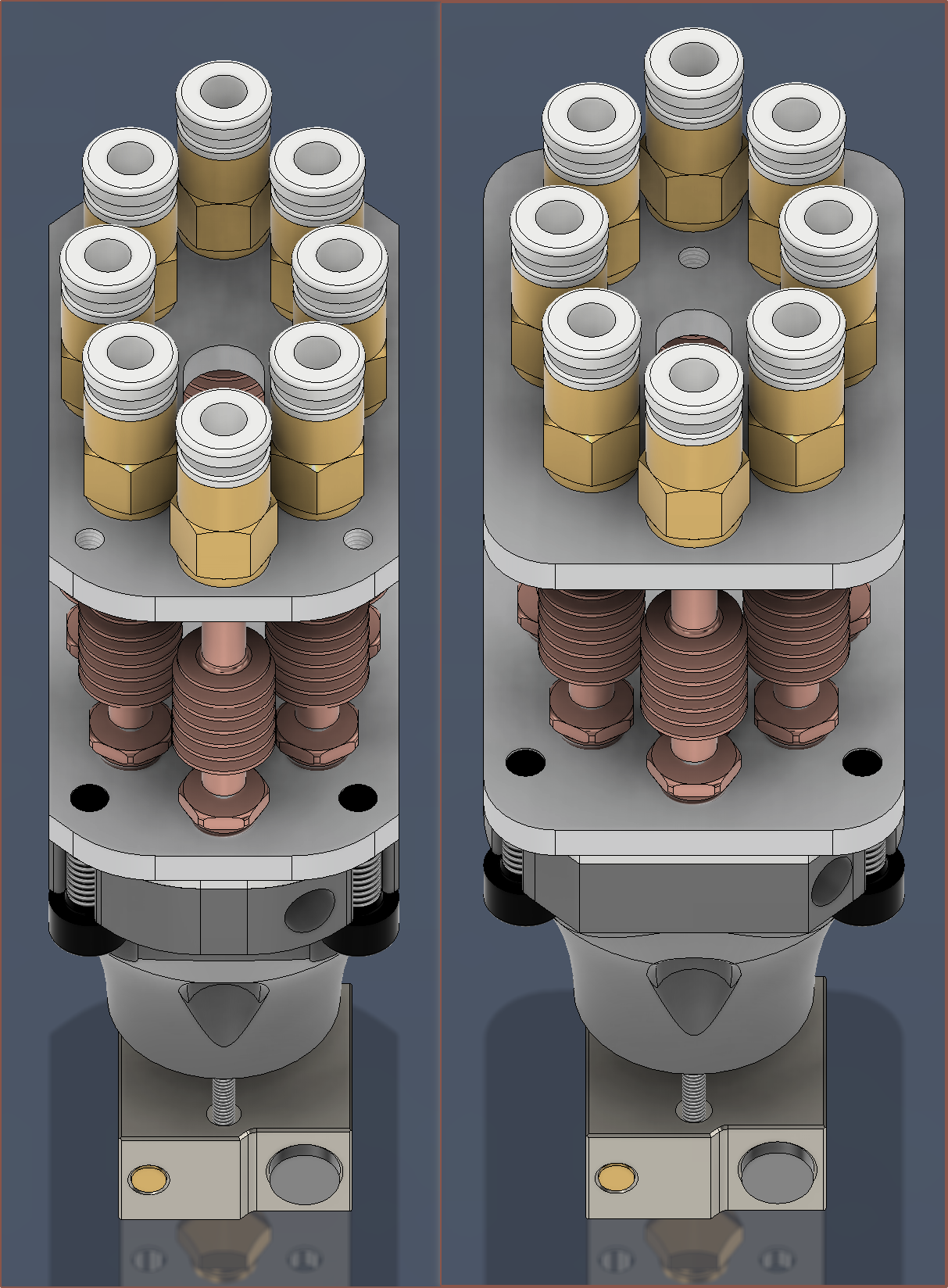
The first revision of the Coaxial8or
The new one is on the left. Also notice how I've been able to use filleted chamfers on the plates too, as I've swapped what edge gets filleted on the heatblock and it no longer would conflict aesthetically. This filleted chamfer orientation is the same as the Coaxial8or cover, providing design consistency.
When I finally finished with the CAD, I was thinking that it looked quite slim considering that the dimensions have only changed from 35*49mm to 30*50mm (notice the divisibility of 7 and 10 respectively as it's one of those nice round numbers that nobody but the engineer (aka myself) would care about). It's only when I got this screen snip that I could certified say that it was notably thinner. At the same time though, the minimum distance between inputs has actually increased (to 11.3mm), meaning that I could use 10mm diameter couplers if desired.
The thinness is important, since I'm trying as hard as possible to preserve a 300*300*300mm print area on my CR600s. Without modifications, a CR-10 or Ender3 would presumably lose only 9mm from the Y axis with this hotend compared to the default hotend (which is 12mm thick).
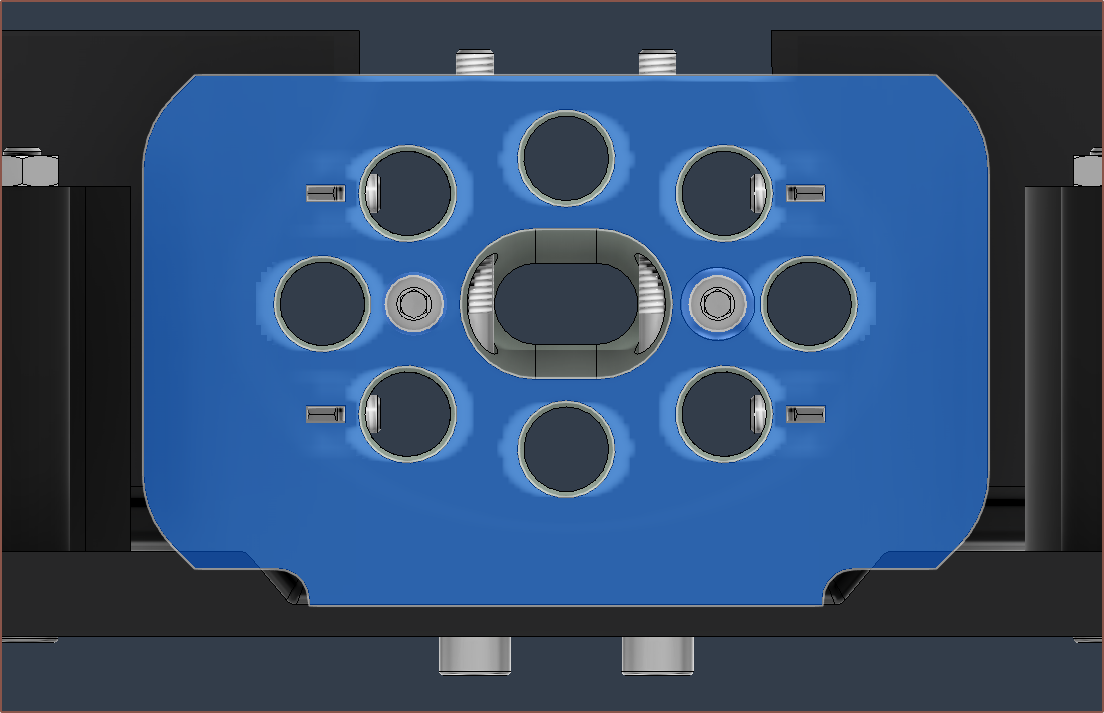
I thought it was game over when I couldn't find space for the M4 clamp plates, but after a break, I quickly realised that I could just delete a 135-degree constraint so that I could move the grub screw hole out of the way.
I've set the centre-offset (the small line on that blue L) to 0.75mm. In other words, the thread line is 0.75mm off from the centre of the cartridge.
I've also now gone with 4 M3's on the outside for the coupler plate, and that's so that I can print 2 halves of a hotend holder and screw them on with an allen key after aligning the heatsinks to the couplers.
I've deleted all the really small triangles that I had made in the negative mould geometry:
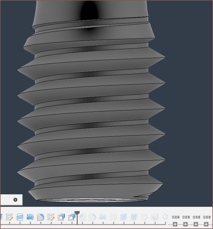
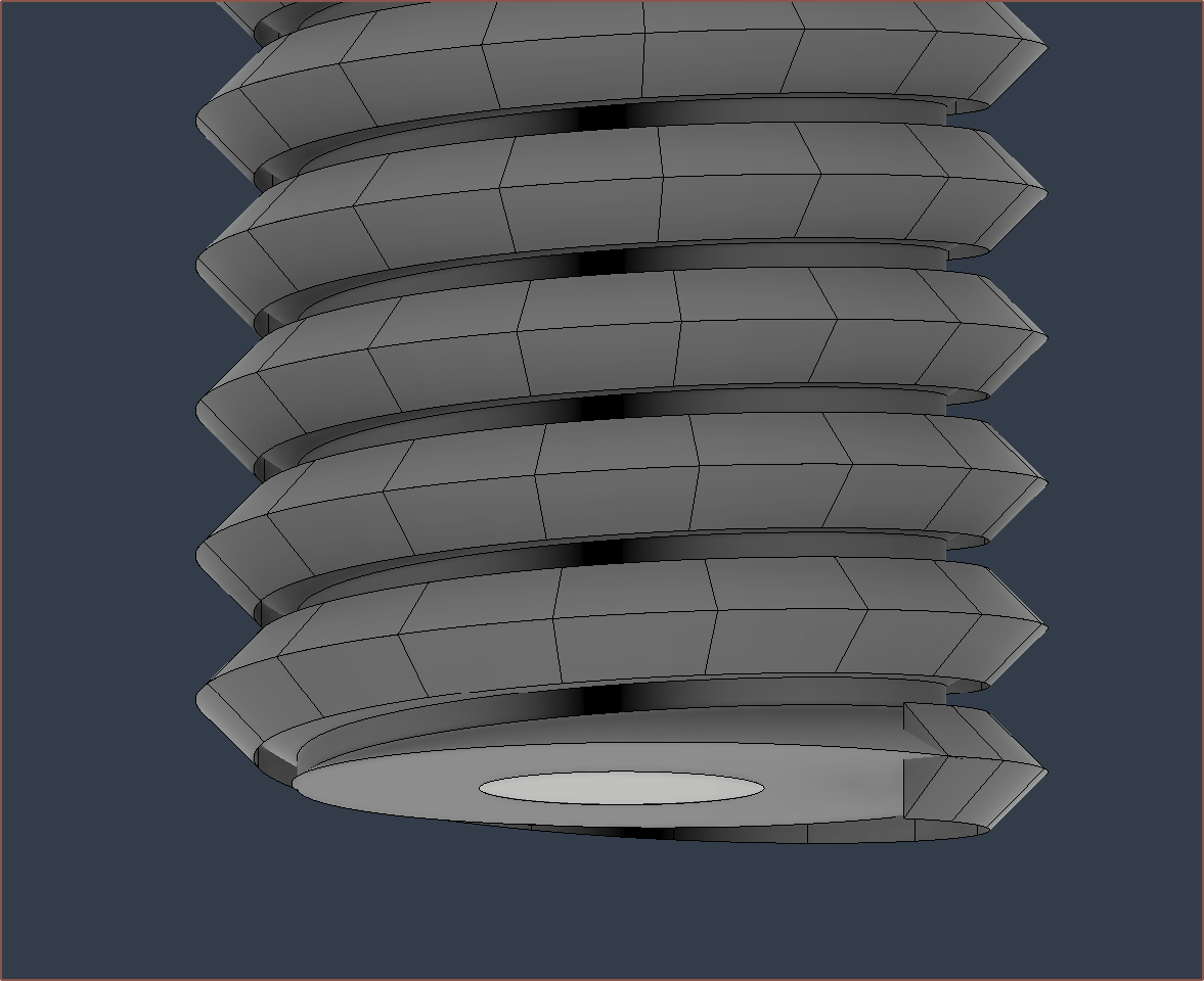
I've sharpened the printed M6 thread since the thread that was printed seemed a bit lacking. Ideally, I'd actually make a custom thread that has 45 degree angles instead of the 32 degrees seen here for a traditional M6:
I also want to mention that I got rid of the legacy Unibody Coaxial Hotend geometry (a.k.a. the heatsink part) from the file.
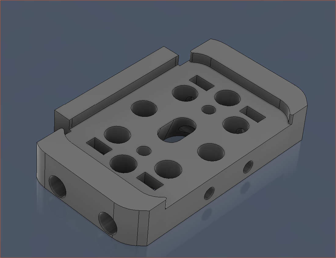
Oh, right, speaking of heatsinks, I've made sure that there's enough space so that they can be taken out without having to unscew any heatsinks. In the currently-printed design, the heatsink covers the heater cartridges by 1 entire millimetre, stopping it from being taken out.
Conclusions
So there you have it, a new design that actually took 3.5 hours to generate, not "15 minutes" as I claimed.
I was just worried that, if I needed to increase the spacing of the coaxialiser center, I would essentially have to be trying to do a respin of everything just because of a single change. Despite me worrying about it all week, I still haven't increased the spacing from 0.95mm, as I want to test out the current one before I increase it. I'm just somewhat glad that, if I desire to get the Coaxial8or respun, it's not a ClickOnce change. Still though, I doubt I would've actually needed a physical model to apply the changes that I've done today.
Trivia
I like how I finished the new design on the 7th save, resulting in "Coaxial8or r1 v8":
As you may also notice, I haven't added a fillet to the main body of the heatblock, and that's because everything was already so smooth and flowing that I thought that the sharp edge in the surface would make it look sleeker and less bottle-like, similar to the surface designs on cars.
[Mar 22]
On the day I ordered the current Coaxial8or print, and today, I was thinking about Mark Rober, a youtuber, talking about what he coins the "Super Mario Effect" (and mentioned by Forbes). The main takeaway is that, with no penalties or drawbacks, participants tried nearly 2.5x more attempts and got a 16% better result.
I found that interesting, but moreso was the flipped around argument; even with a penalty and, as a result, attempting 2.5X less, the other participants were only 16% away from a more optimal result. This gave me the confidence to finally order the hotend, knowing that "well I'm probably within 16% of the optimal solution".
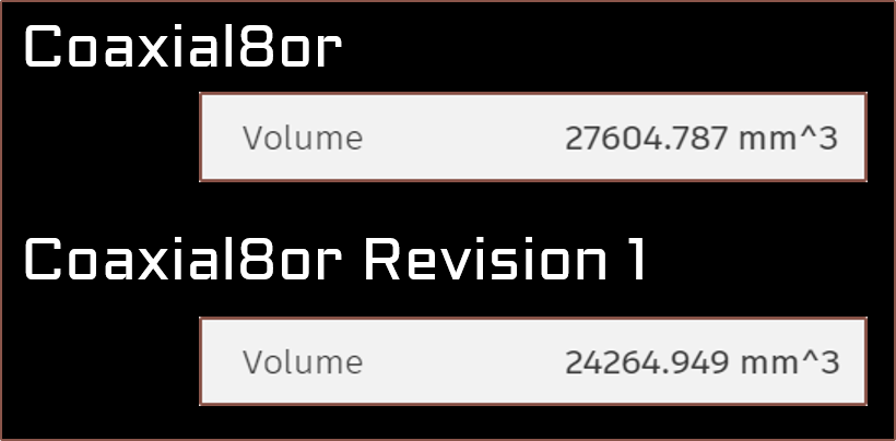
Today, I was able to get the depth down to 29mm and mass to 63.5g. To sound a bit like Apple, the resulting design is a 17.4% reduction in depth and a 14.7% reduction in volume from the current "r0" design. I've broken the sub 24,000mm^3 barrier and now the heatblock sits at 23,555mm^3. It also means that I've now cut the Y offset by a round 3 milllimetres.
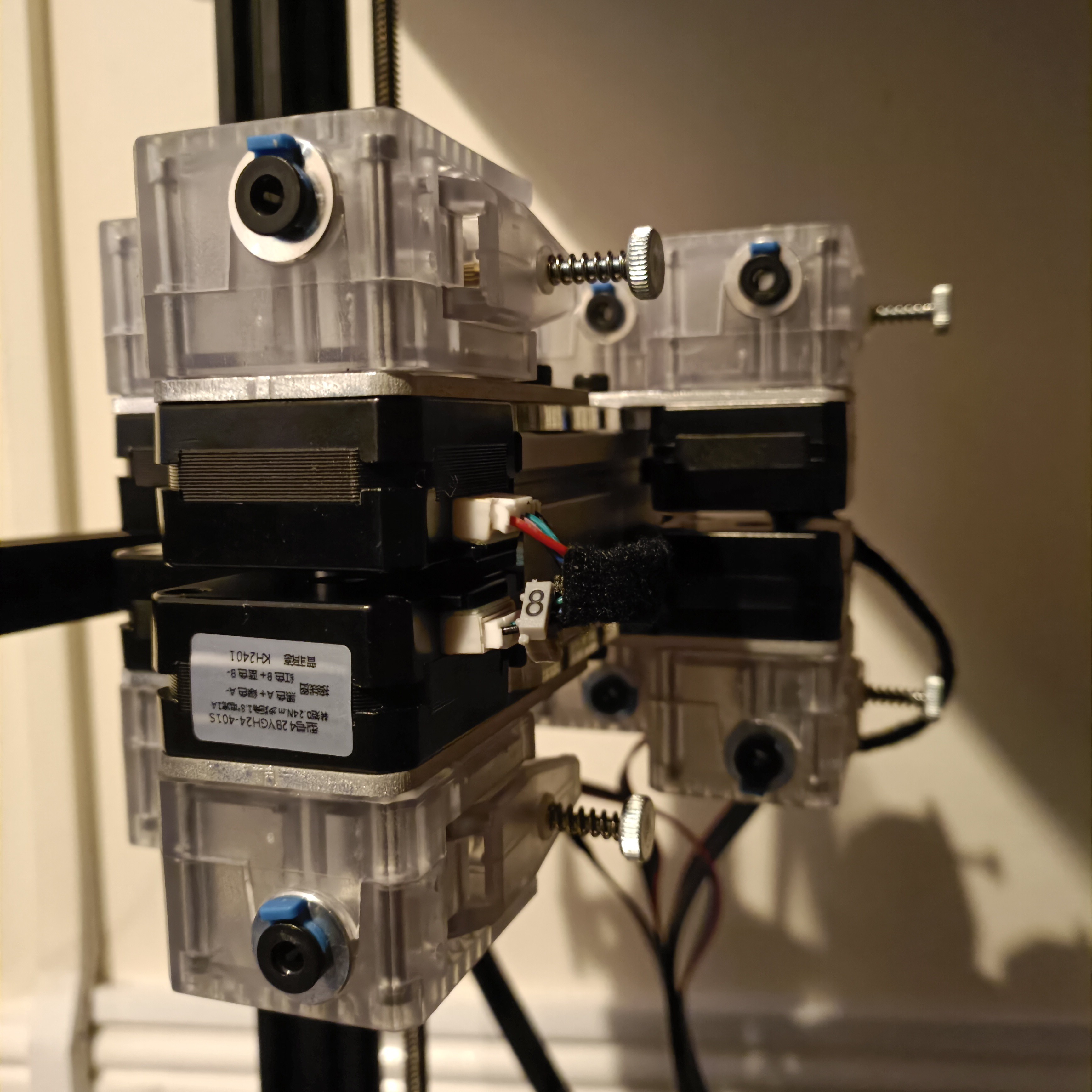
So I should mention some thing if anyone is planning to use a 3mm mounting plate and 35mm bolts with these DDE extruders:
The holes that they go into are 5.5mm for the bolt cap, and unlike the ones that come with the extruder which is 5mm, the bolts I got in the mail are 5.35mm meaning that the tolerancese are tight and thus need more effort to screw in. The benefit is that they're unlikely to unscrew due to vibrations.
I needed to use M3 washers (that my university happened to have) to have enough clearance between the end of the bolts and the thread depth of the motors. The washers are 0.48mm.
Other than that, they seem rather nice:
They're translucent so I can see things like mounting bolt depth, if the motor gear is turning, how deep the bowden tube is...
There's a small cutout to be able to pull the bowden coupler as far forward as possible. It move slightly inwards when pushing the bowden tube in.
Perhaps it's the thinner motors having less unpowered torque, but I find that the metal gear is both easier and more comfortable to spin than the plastic gear.
It's much easier feeding filament in compared to the black ones I had.
It seems that the perfect height for the motor gears is such that the bottom of the gear coincides with the bottom of the D shaft section of the motor.
Holder
So I had the hypothesis that it was the holes in the hotend holder that was preventing me from just aligning the heatsinks by feel, and so I made a through hole of the clearance holes used to allow the M6 threads to stick out from the other side of the coupler plate. The good news is that it worked and the grub solution seemed to work nicely (I only needed to softly tighten them for the assembly to stay fixed in place. The bad news is that I did all this in "Isolate" mode and didn't check for intersections:
It worked, but it was not ideal, so I did a respin with the extras cut out.
I modelled those side-wall, locking screw holes to be 6mm for the M3 bolt head, but it was hard to get on. I've changed them to 7mm so that it should be easier in the future. Actually, the same could be said for the M3x45 holes too, since instead of the handful of seconds I was expecting, it took multiple minutes to slowly screw the 45mm long bolts though the entire thing.
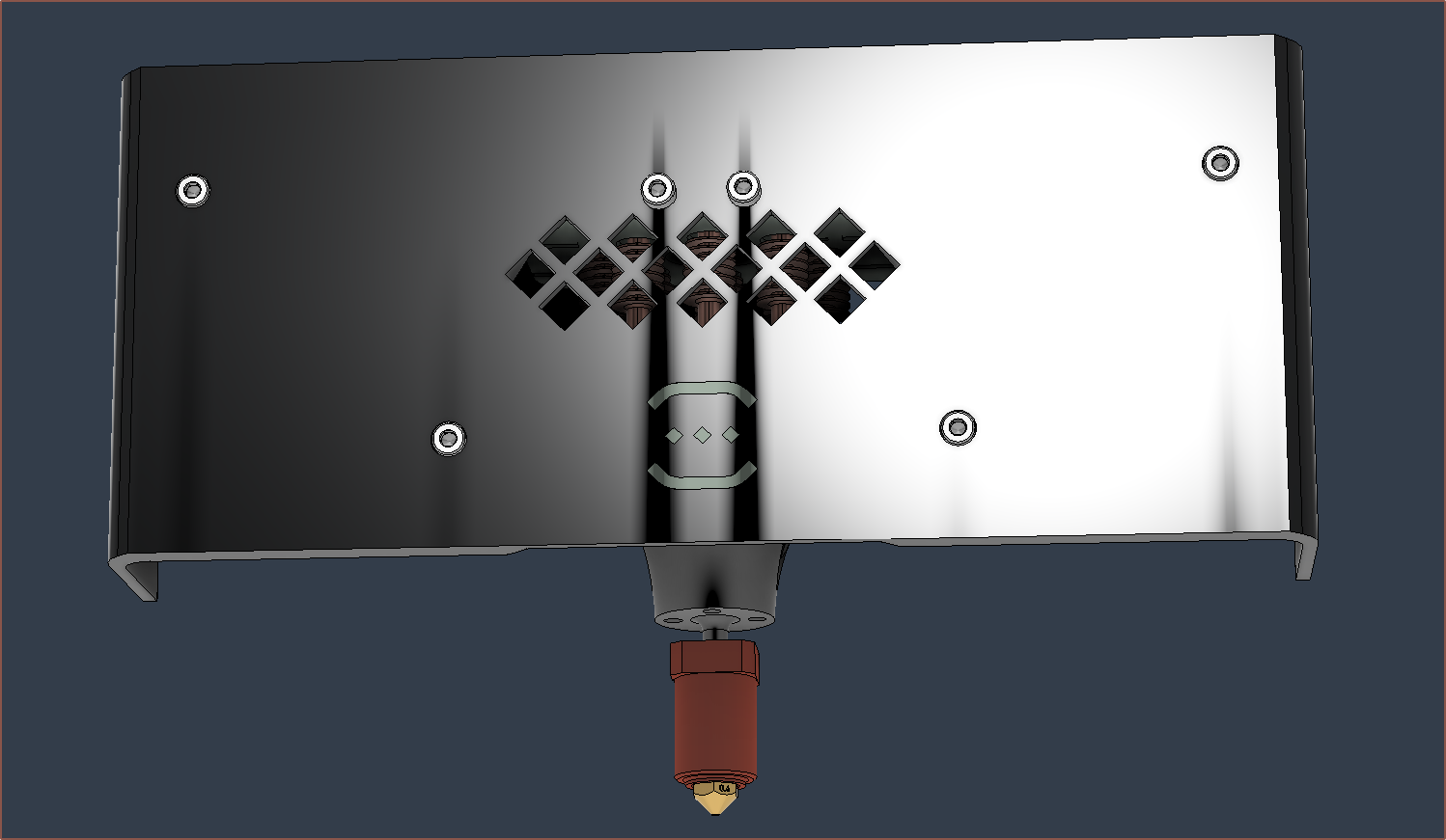
This quick cut was after I made the changes for when I reprint the cover. One of the changes is that I've flipped over the fans because I found out that one of them has a broken clip that is supposed to act as a wire strain relief. There should be enough of an air gap for it to work, and it means that I can reduce the size of the grill:
I also took this time to (somewhat slowly) helix-ify the 70W heater cartridge wires.
Bowden tubes
For E0 to E7, I've gotten { 50, 50, 46, 50, 36, 40, 36, 36 } in centimetres for the lengths of the bowdens.
You can also see the kitchen roll I used to prop the X gantry up while I was installing the extruders.
I then put black filament through (so that I could easily see it through the PTFE) and pushed untill I couldn't see it anymore and then pulled back until I could. Then I'd look at how much I pulled out and if it was about the length between the heatblock and the coupler, I assumed that it went all the way in. For those that didn't, I unplugged the PTFE tube, thread some filament in (approx 40mm) and then thread that into the coupler before putting the PTFE back on. That seems to ensure that the PTFE is properly aligned as it solved the issue every time so far.
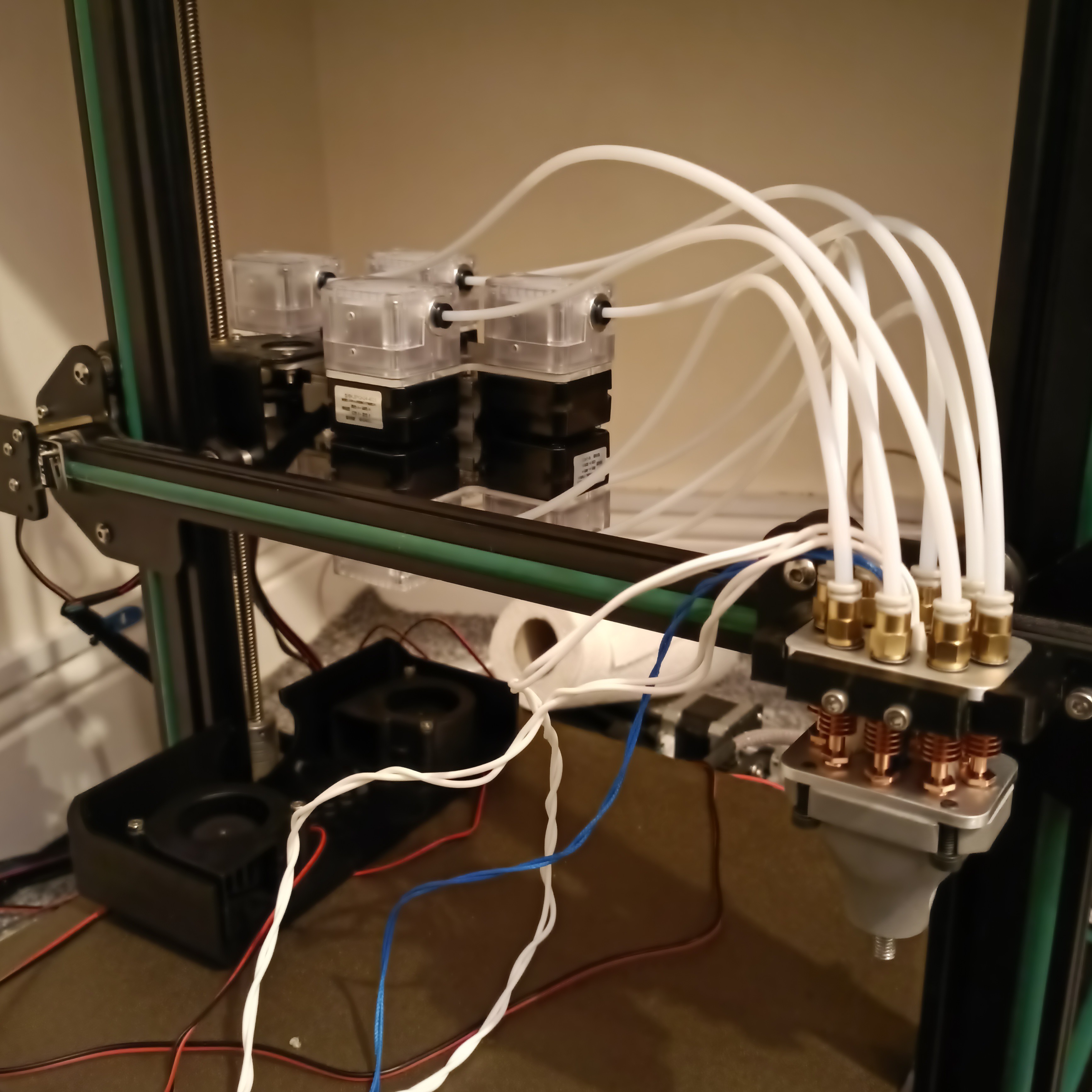
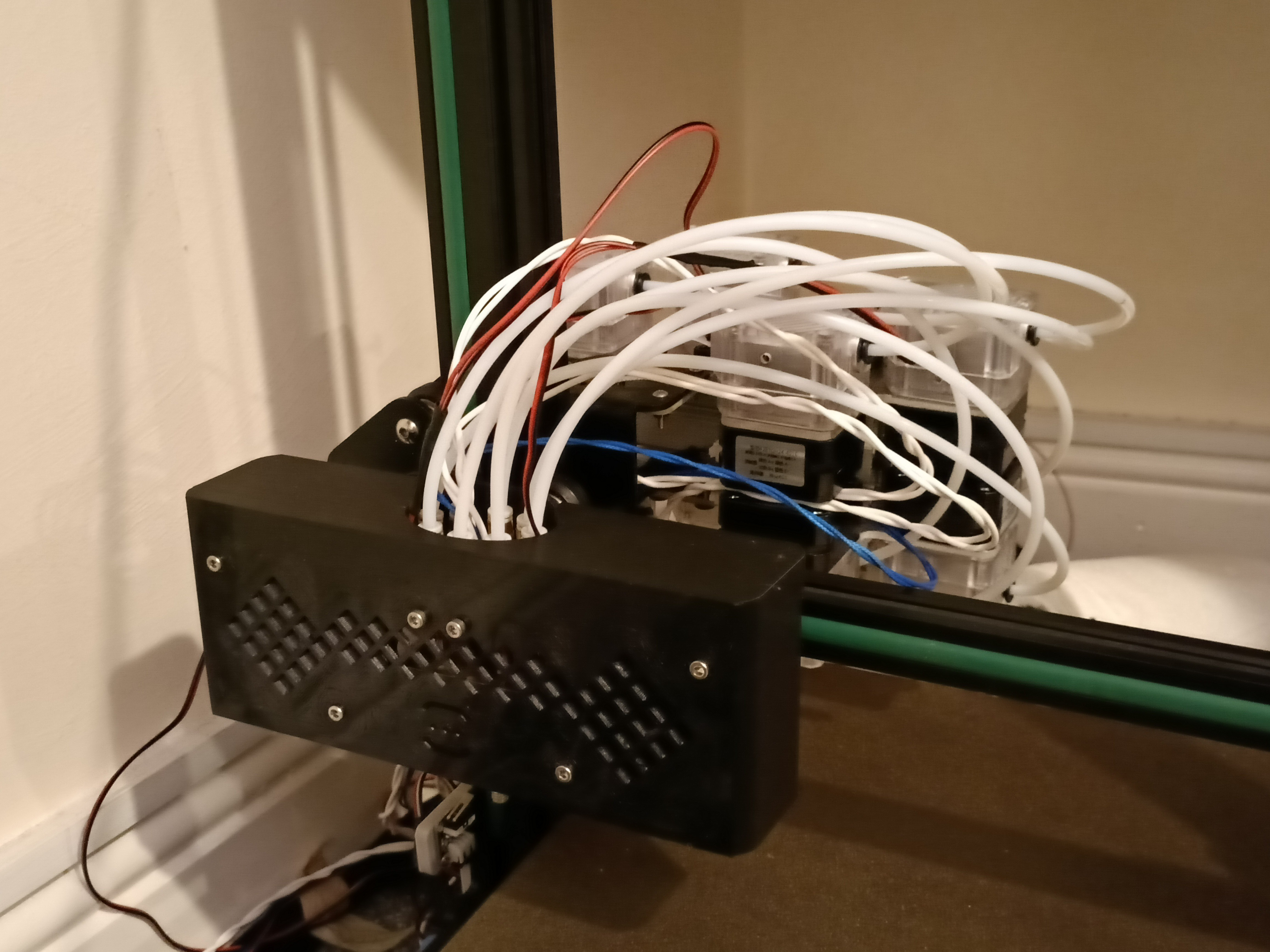
Lastly, I installed the cover:
I wasn't expecting the end result to look so messy.
 kelvinA
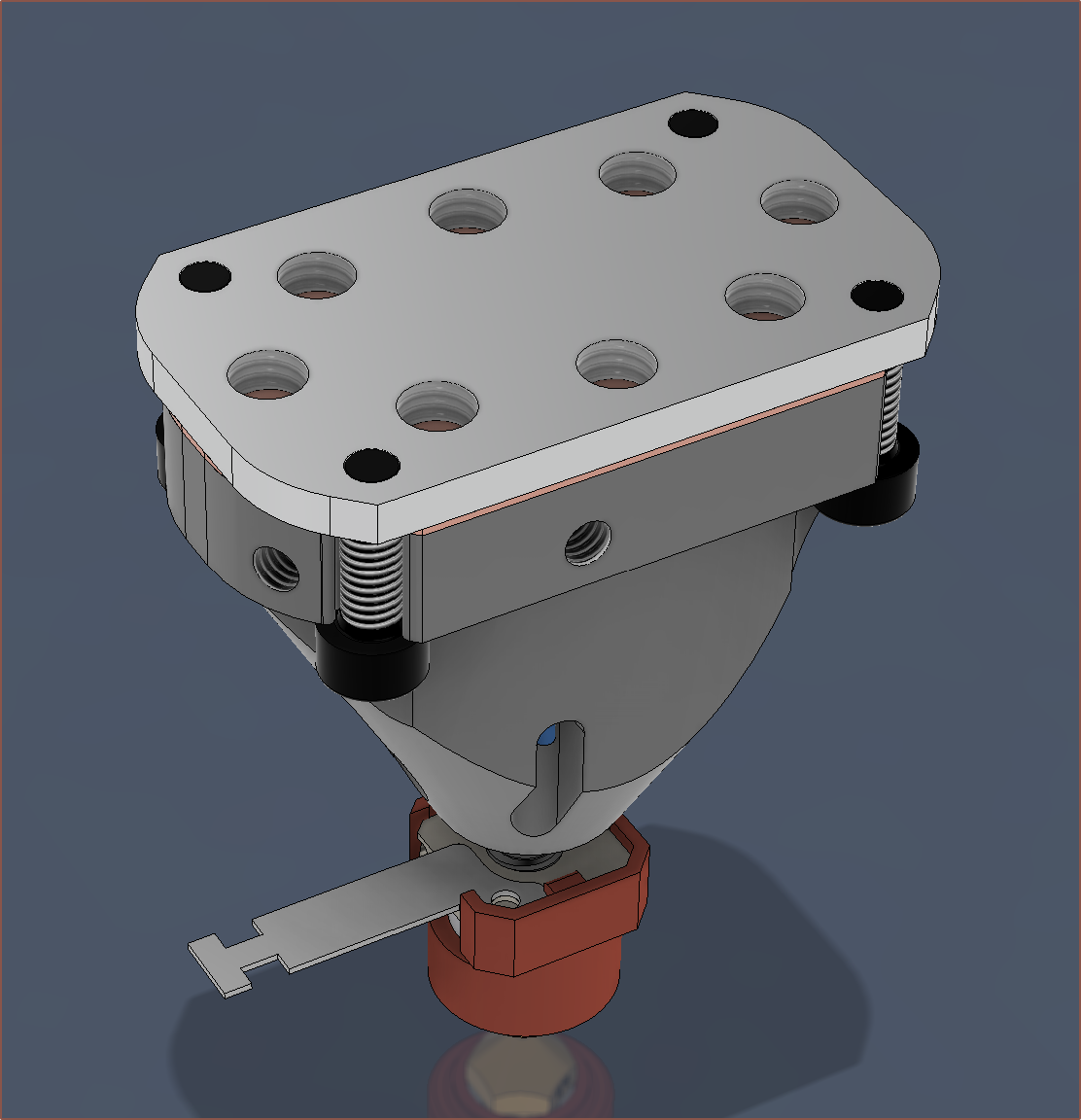
 I started today with an extrusion test to get some real numbers for volumetric flow rate. So that I could also finally answer the question of "Does it coaxialate?", I decided to create a virtual filament of white + some other colour.


 This is when I decided to look for leaks. I peeked through the grill and the back of the cover and saw no leaks peeking out anywhere. The mysterious synthetic odour I forgot to mention in the previous log was also much lower to the point where I forgot about it; I assume it's just like getting any new appliance and heating it up for the first time. I was also able to loosen the nozzle when cold, which is another good sign that there are no leaks. Lastly, the face at which the coaxial8or meets the nozzle still looks clean, so I assume that the leaking issue has been sufficiently addressed.