 Bud Bennett
There has been a lot of DIY effort to make a good, cheap constant current electronic load. I must give homage to the efforts of past attempts, mostly successful, to create something useful for evaluating a power supply's capability or a battery's capacity. It's not easy.
One of the best is Dominik's: https://github.com/Dominik-Workshop/Electronic_load/tree/master
His implementation covers most of the bases and we used it as a benchmark. But it is a bit lacking in user stupidity protection. (And we wanted more.)
Another implementer worth mentioning (besides our eminent Hackaday colleagues) is John Sculley with his excellent treatise on YouTube: https://www.youtube.com/playlist?list=PLUMG8JNssPPzbr4LydbTcBrhoPlemu5Dt
But alas, Mr. Sculley descends into the mire of fixing unforeseen predicaments in a seemingly never-ending fix-it scenario. I guess a nice way of putting it is "Feature Creep".
We recommend viewing Kerry Wong's excellent YouTube videos (https://www.youtube.com/watch?v=WUPrj03UbTM) on Linear MOSFETs for an education in the reality of "Safe Area of Operation", or SOA, for the uninitiated.
A Bit of History
Paul has been working on this for a while. I entered the scene when he had a problem with oscillation that he couldn't explain while evaluating his latest prototype. Paul's blog on this subject is here: https://www.paulvdiyblogs.net/2022/08/dynamic-acdc-load-cc-cv-cw-batt.html
He was attempting to design/build a DC/AC electronic load. I have no need for an AC dynamic electronic load, which is a lot more complicated to design and build, so we settled, temporarily, on a DC version.
A lot of issues have not been entirely addressed yet. There are both hardware and software problems that remain to be addressed, but we're hopeful to overcome them with a bit of persistence.
Project Status (2024-05-19):
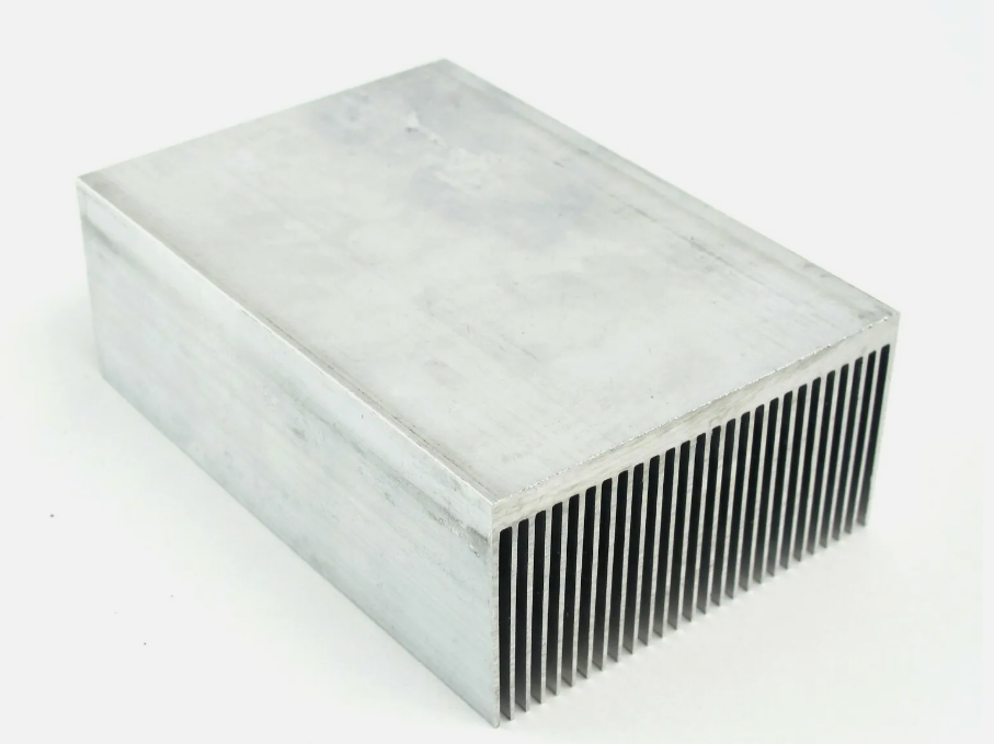
We are releasing the second pass PCB today. There was a couple of weeks delay while we searched for an readily available heat sink that would allow at least 150W of continuous power dissipation. The heat sink is flat finned 100x69x36mm aluminum extruded. The PCB will be mounted above the flat surface of the heat sink and the NFETs and temp sensor will have 90 degree lead bends and attached so they are parallel to the PCB instead of orthogonal. See the layout discussion below for details.
There are now two fans for thermal management. One fan, 92mm, will sit below the heat sink and blow air up into the fins. The other fan (60mm or 80mm, TBD) will be mounted at the rear of the enclosure and suck air out of the enclosure. We have not tested this in an enclosure yet, but it works on the bench. The two fans will be wired in parallel -- there are two 4-pin fan connectors on the PCB.
The enclosure is another problem. It should be plastic, to isolate the heatsink (which is connected to the output terminal) from the user. Paul found an acceptable enclosure -- a Teko AUS 33.5 (198x178x108mm) -- but it is not readily available in the USA and the shipping is costly. Paul is going to create PCB panels for the front and back to make it look less DIY, so this is the only enclosure we recommend now.
Target Specs:
Input Voltage: 1V - 100VDC
Input Current: 1mA - 4A for 40V < Vin < 100V, 1mA - 10A for 1V < Vin < 40V.
Maximum Power Dissipation: 150W (Depends upon heatsink and Fan. Bud still has doubts.)
Voltage Accuracy: 0.2% (Trimmed, but there are temperature drift terms.)
Current Accuracy: 0.6% (Trimmed. Best guess right now. Mostly temp drift error.)
Lowest Conductance: TBD. (Current NFETs + Sense R + Relay contact R = 75mR)
Ripple: TBD
Protection: Reverse polarity to -100V. 15A fast blow fuse at input.
Power Input: 12VDC/1A Wall Adapter. Reverse polarity protected to -24V.
Cost: $TBD (Maybe $100 depending upon enclosure/fans/heatsink and where you order components.)
User Interface:
Display: 128x128 Color OLED.
User Input: Rotary Encoder with push switch. Remote/Local...
Read more »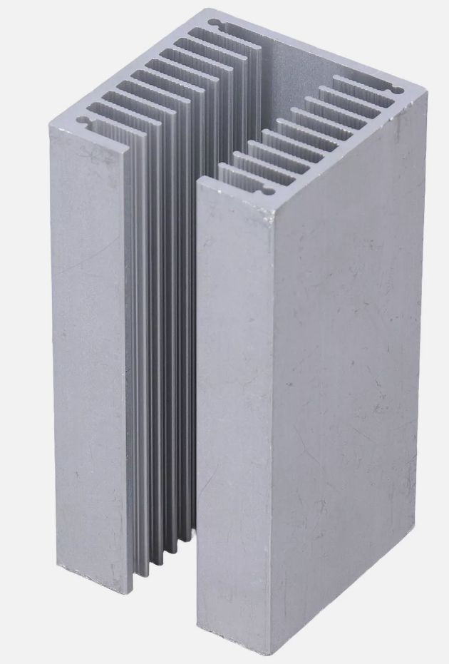
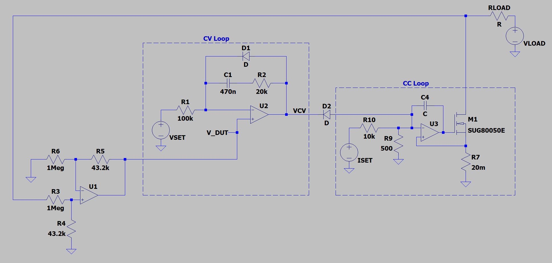
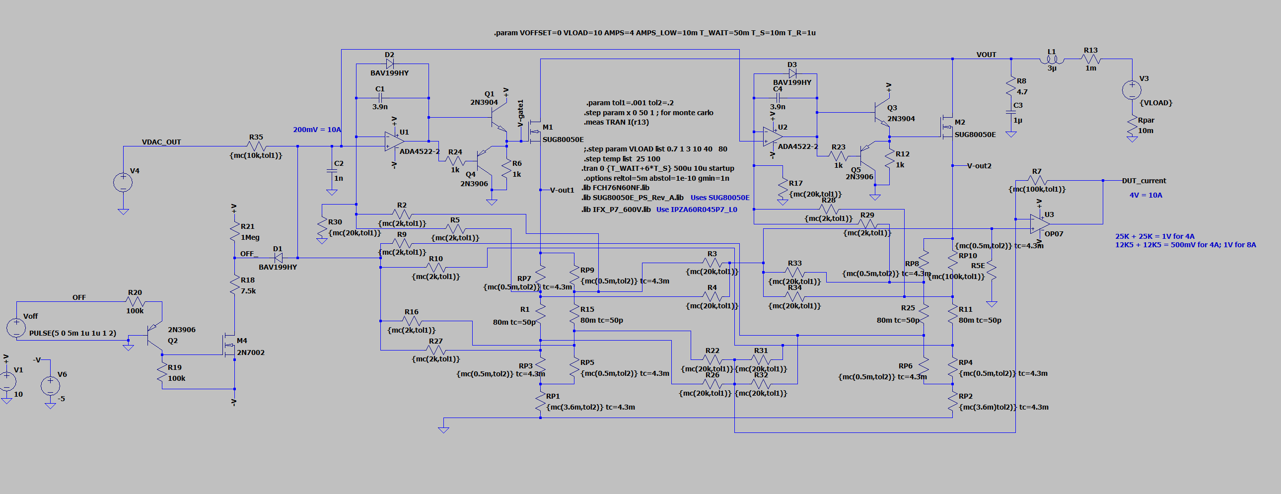
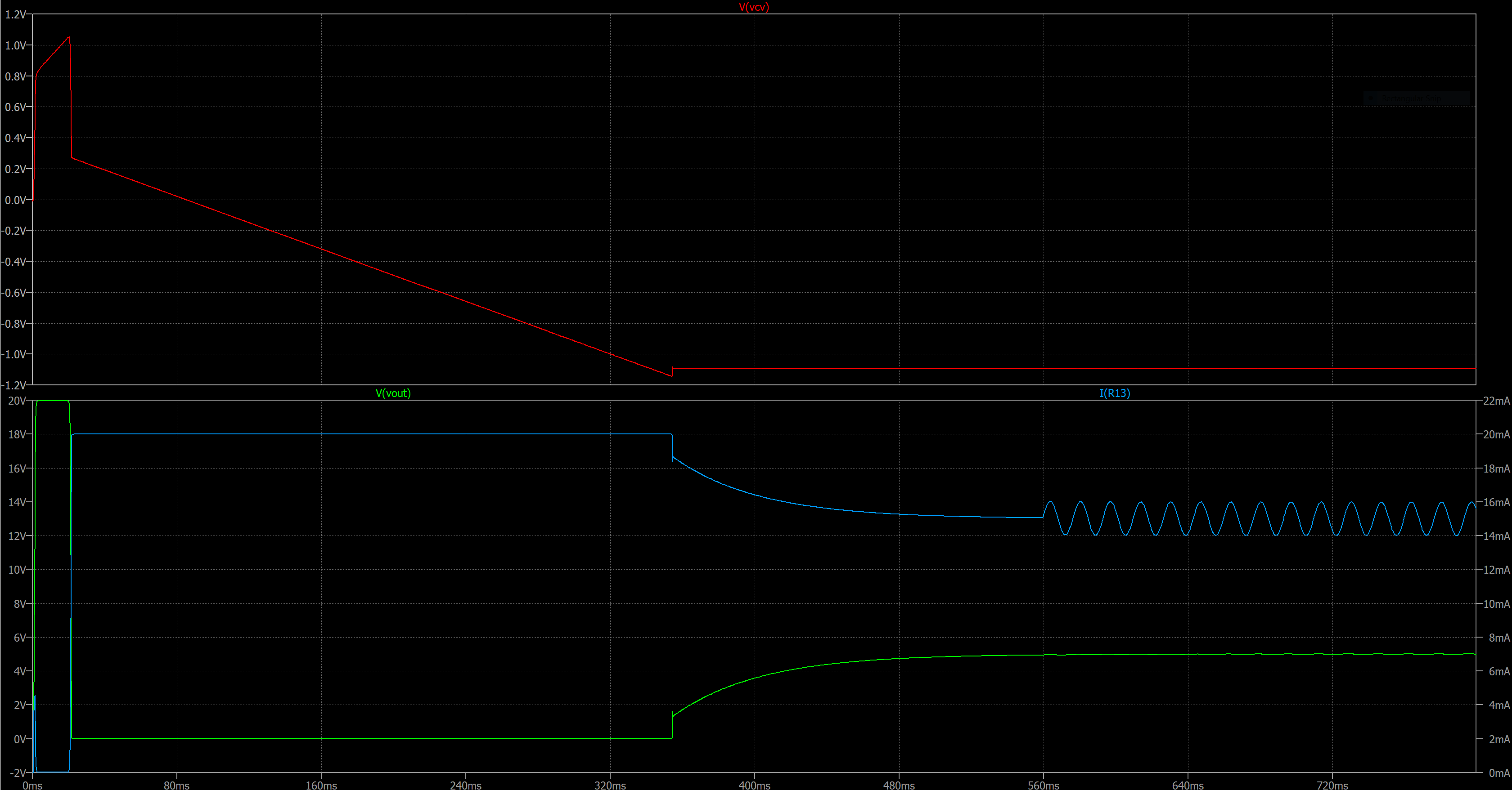 The system is held at zero output current for 5ms and then released. The CV opamp is out of control until VSET changes from zero to 0.2V, but it has to slew to 1.2V below GND before it takes control from the CC loop. Since the CC loop can output 125mA it drives the output voltage to zero (125mA x 1k = 125V, but only 20V is applied). Once the CV loop overcomes the CC loop the current decreases in the CC loop and the load voltage rises to the set point (5V). A 1V-peak sinusoid on top of VLOAD is applied at 560ms to show that the CV loop can keep the output voltage stable when disturbed. I think it performs pretty well, if slowly.
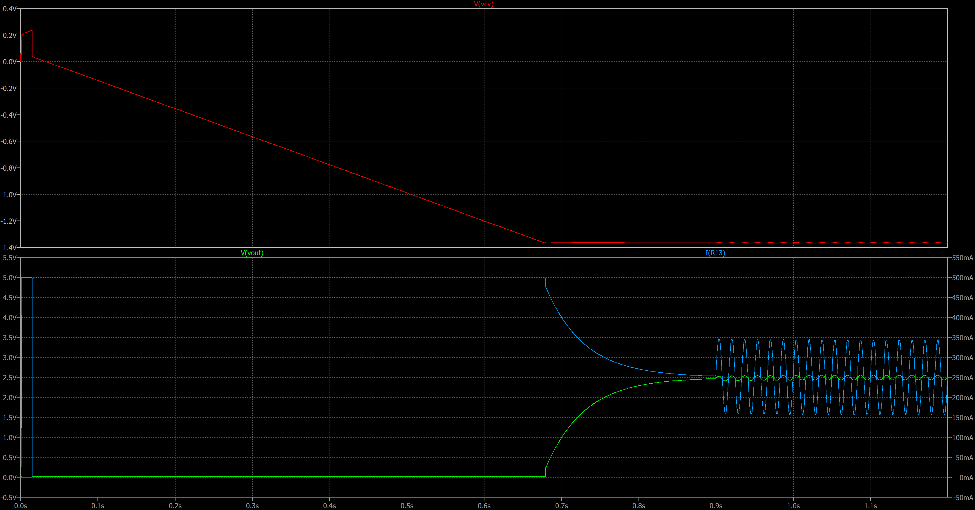
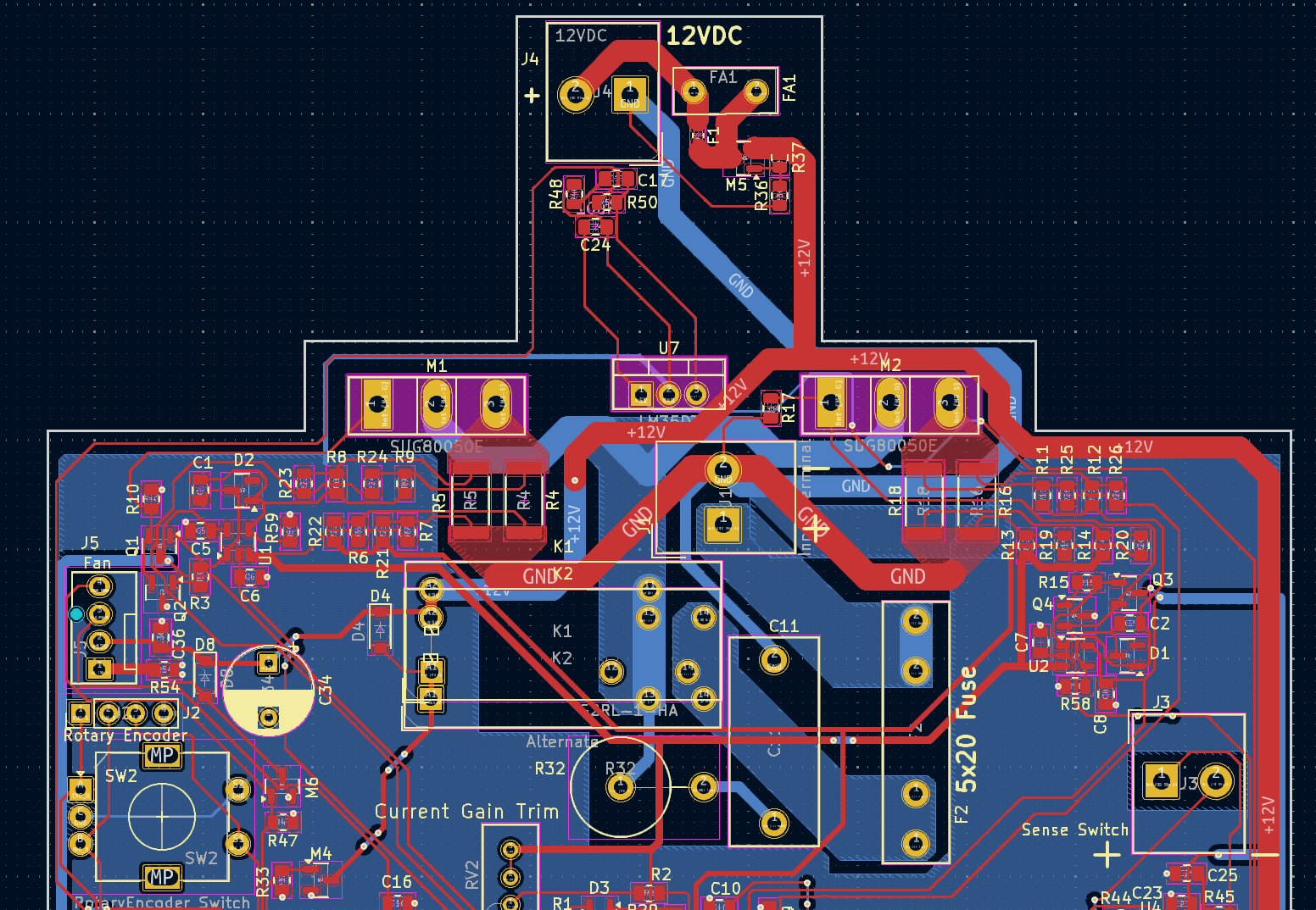
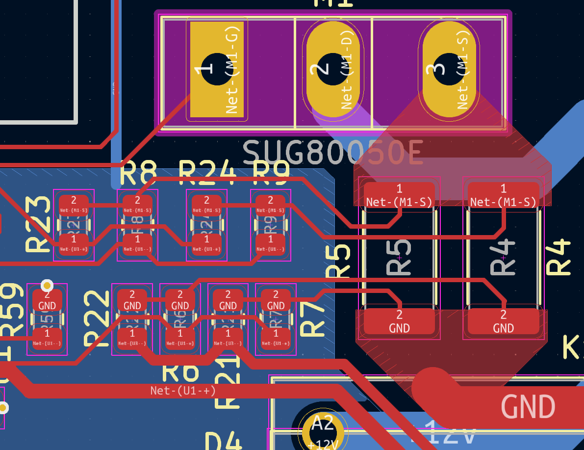 The current tends to spread in 45 degree funnels from a single point to a connection point, such as a pad on a component. In order to make the Kelvin connection the current should be zero at the point of the Kelvin connection. I made triangular copper pours to distribute the current to the two sense resistors. The back-side of the pads should have zero current flowing to it and therefore a good place for a Kelvin pickup. The pickup points are on the middle-inside of the pads on the sense resistors. Those traces connect the feed resistors for sensing the voltage across the sense resistors.


 jbb
jbb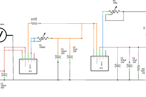
 MrWunderbar
 James Wilson
 Richard Dudley
Hi,
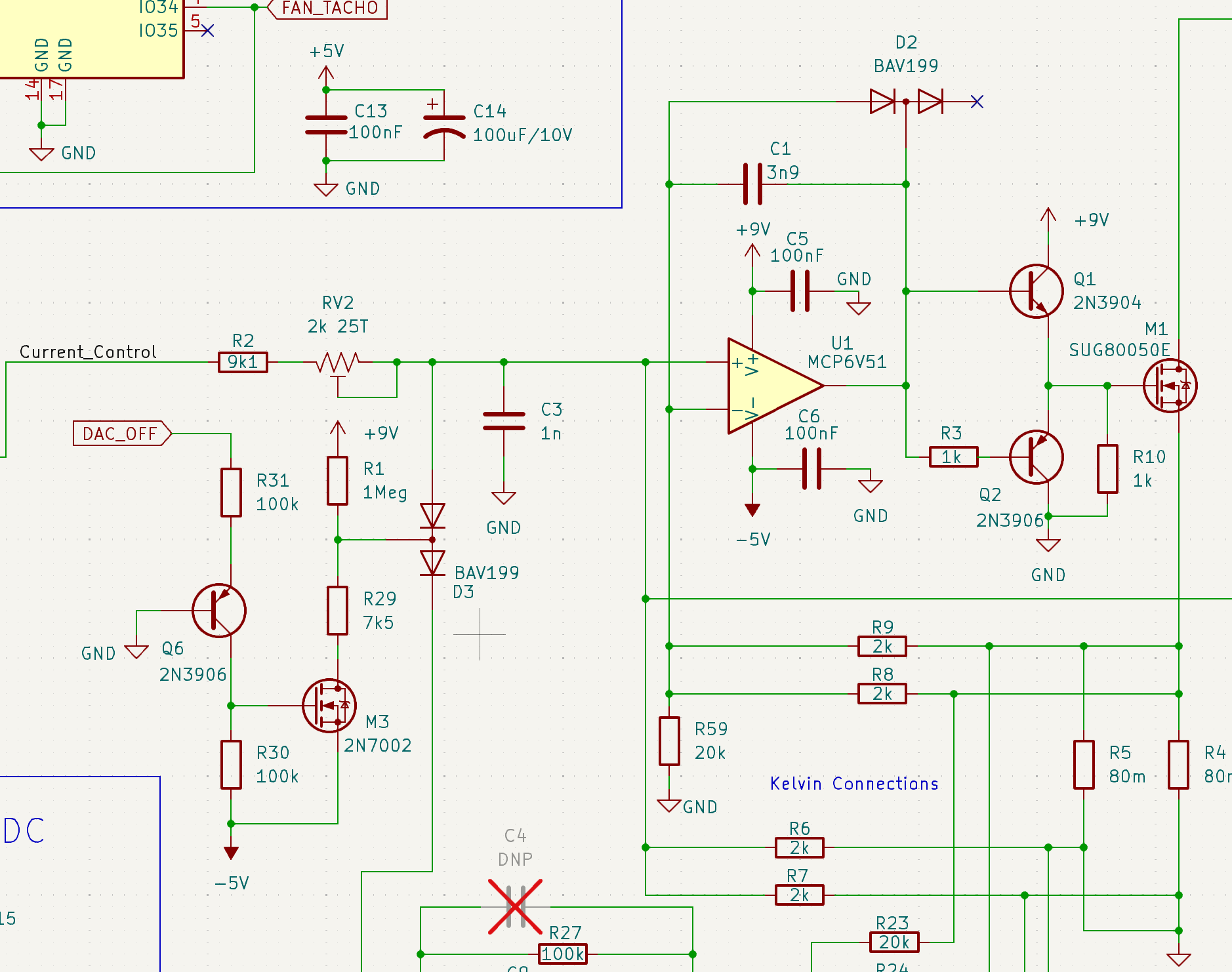
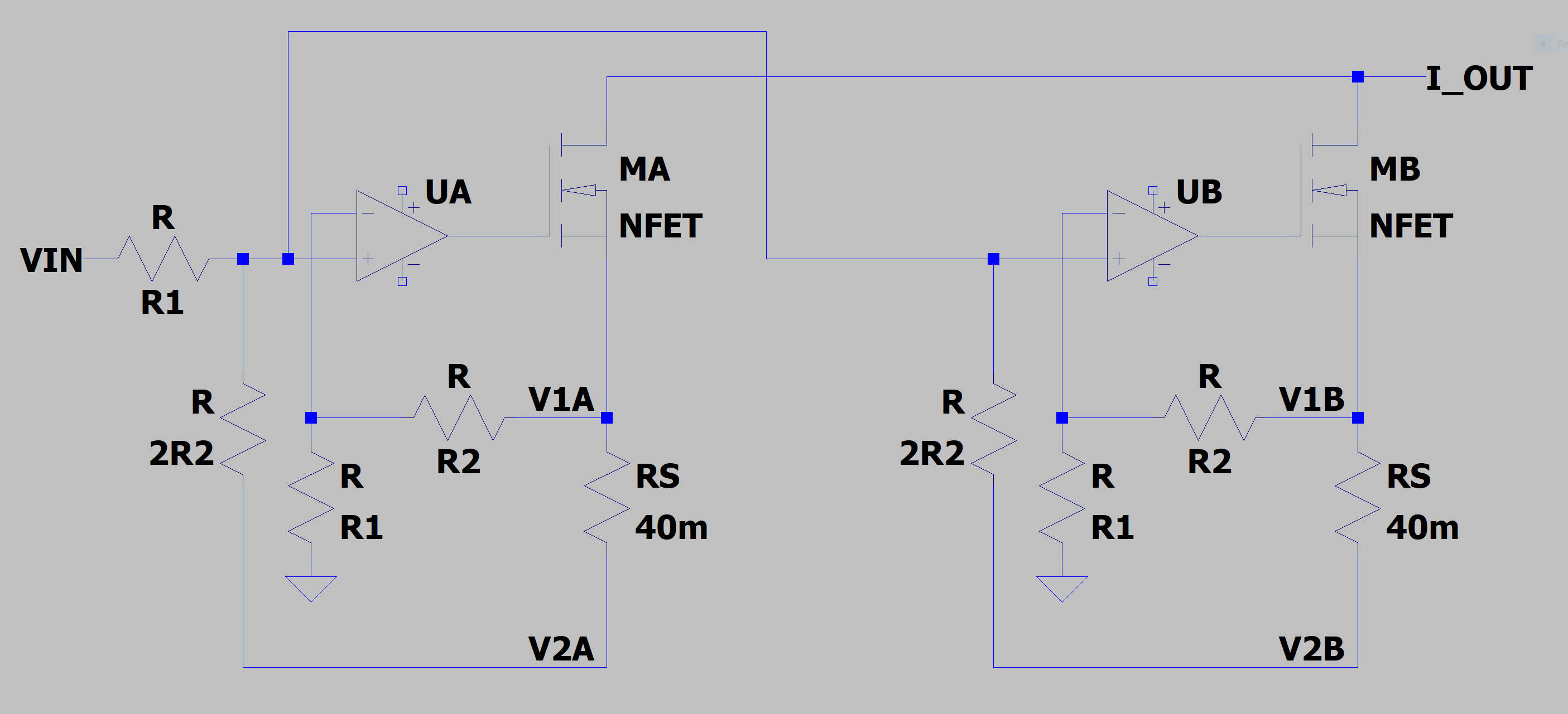
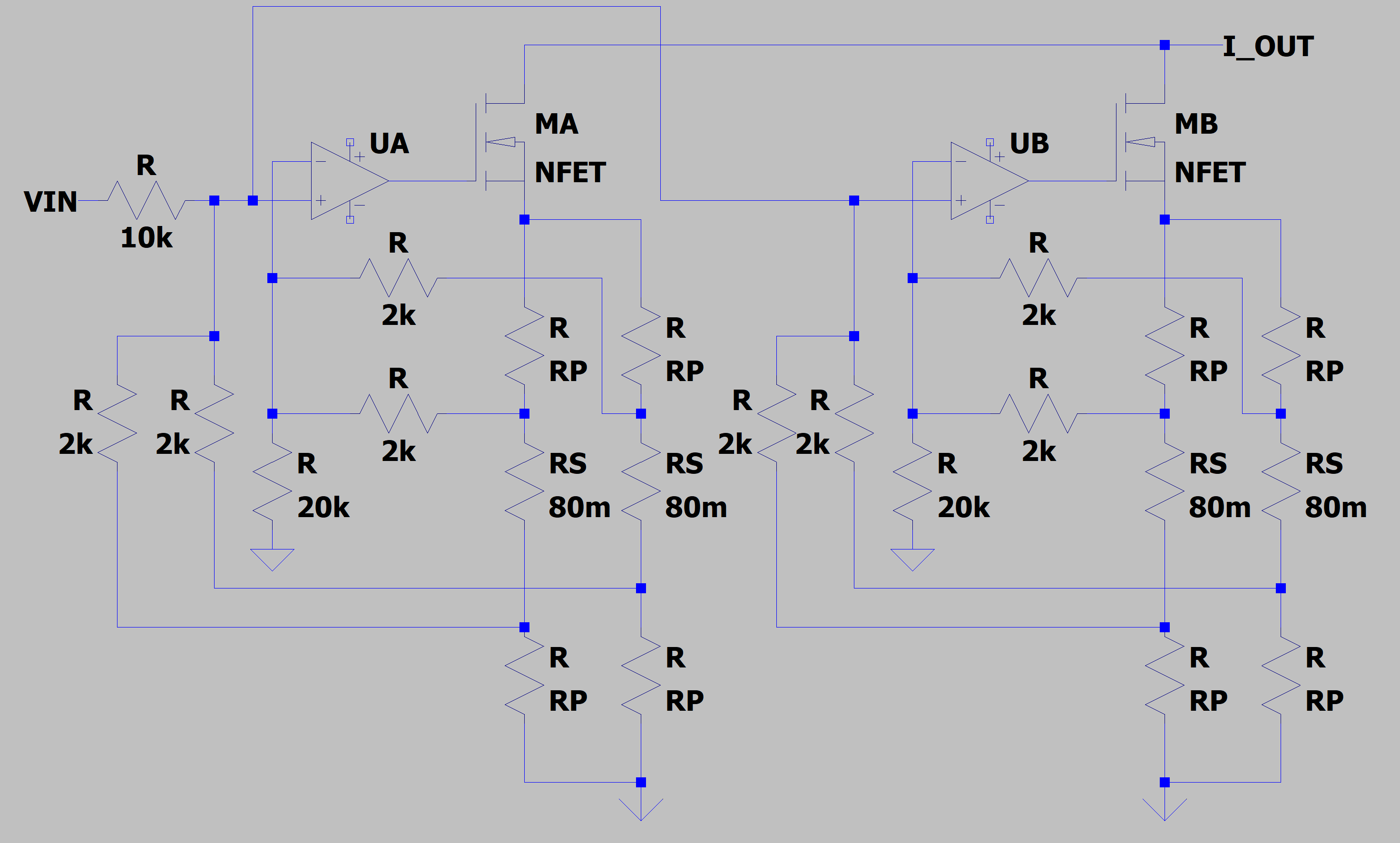
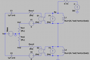
Looking at your schematic, I see two completely separate output sections including sense resistors. Is that setup going to load share properly?