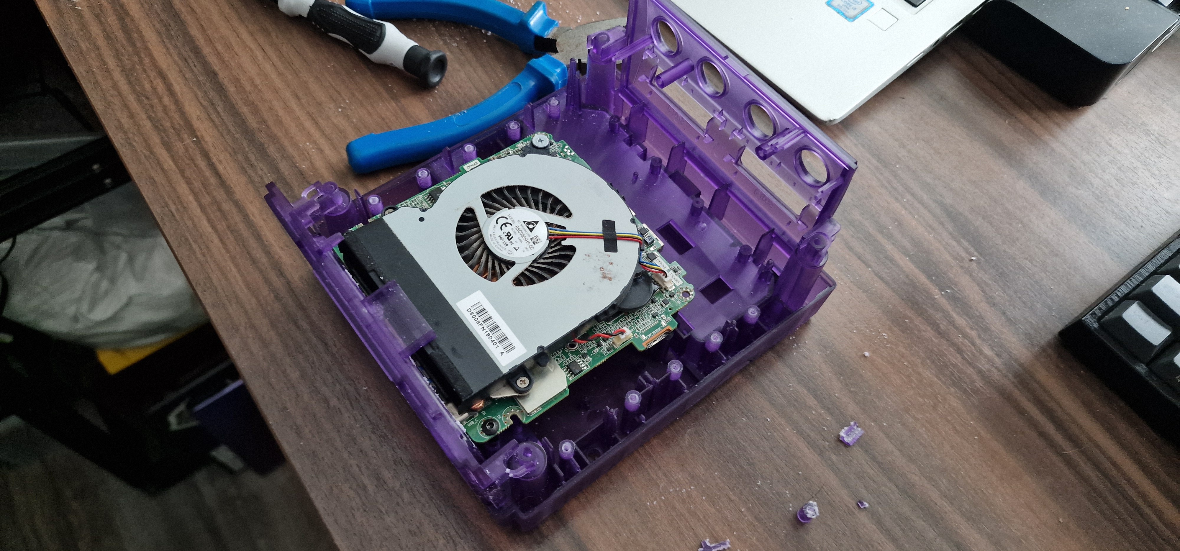
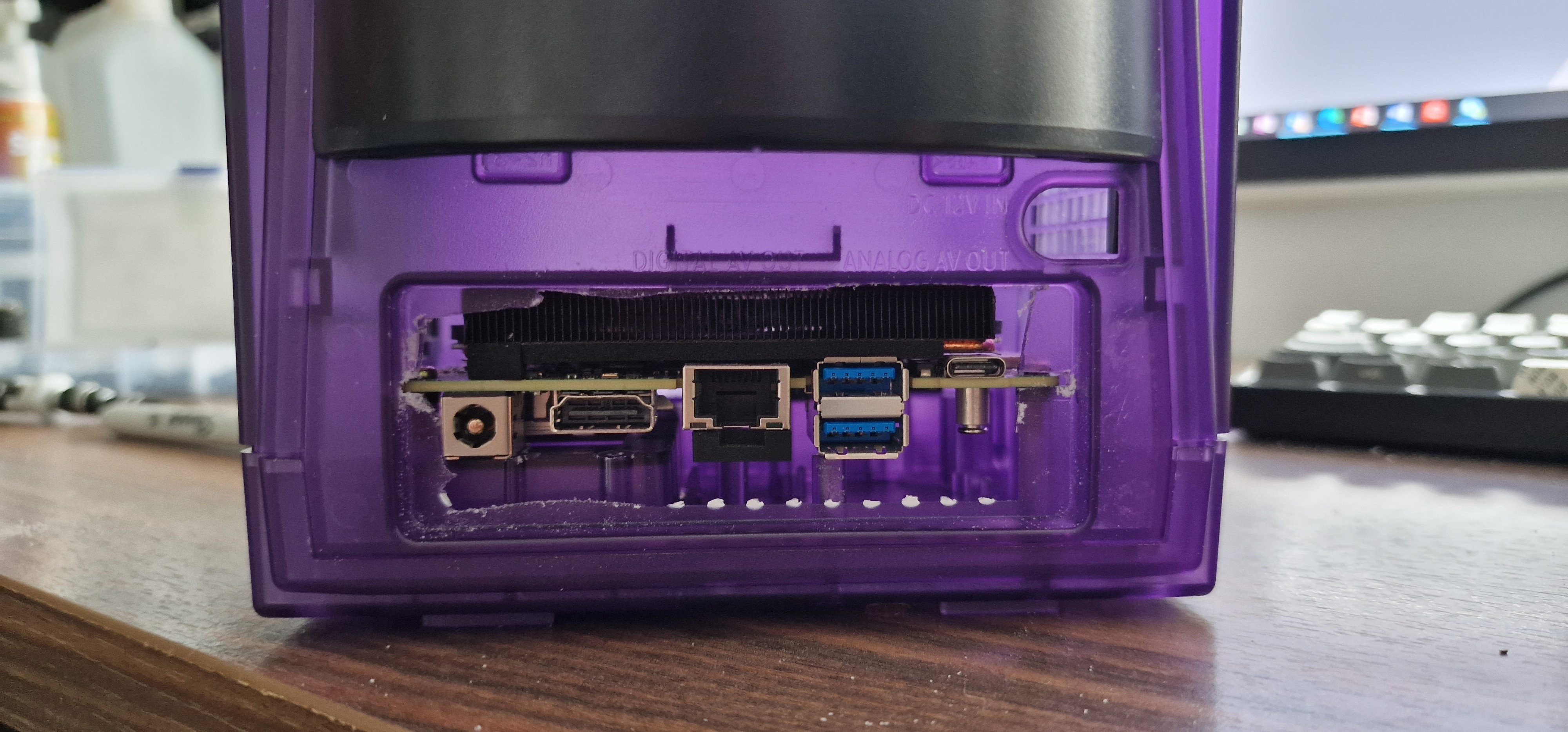
• Power Button Pt. 3

    Jamie5 days ago 0 comments

    Long time no see eh?

    I could give you the whole spiel about my exams getting in the way etc. but between me and you, I am simply just a pathological procrastinator.

    JLCPCB Order

    Let's get cracking with where we left off. Firstly, PCB V0 arrived from JLCPCB:

    And, I have to say, I was very impressed. I wasn't paid by JLCPCB to say this, but the quality was fantastic. 5 boards arrived pre-assembled and the total cost including shipping was just £24.08 (That's $30.50 for you yanks across the pond) and it only took 10 days.

    Despite this, these boards were absolutely useless to me. So I guess they'll look pretty in my box of random electronic components for a few years until I decide to make art out of them or salvage some components.

    PCBWay Sponsorship

    Whilst pondering over the limited funds in my bank account, I decided to check out PCBWay's sponsorship program. I figured there would be no harm in submitting an application (Here is the post in case you were interested) in the hopes that I could get some support from them to fulfil this project. 

    Shortly after being accepted for sponsorship, Liam independently slid into my DM's and asked if I would be interested in collaborating with PCBWay on this. He provided my account with the funds to ensure all of my V1.1 boards could be assembled in house rather than just one or two. This would have come to a total of £48.17 ($61.01).

    Over the next 19 days I obsessively checked my order status until the boards arrived in my hands. I will admit, I was slightly addicted to the thrill of seeing it move through each stage of production. And don't get me started on the excitement I felt when they even sent me a photo of one of the boards to make sure everything was up to standard before shipping! 

    Throughout the process, the engineers had a few questions which, instead of simply assuming the answer to, they pinged my way. I was surprised and impressed with this level of service given how quickly the turnaround was. 

    With all of this build up I'm sure you're absolutely on the edge of your seat in anticipation to see some photos of the finished boards, so here you go:

    Programming the ATTiny85 with Arduino Uno over ISP

    I hooked up the board to an Arduino Uno and took the following steps to program the ATTiny85:

    1. Select the Arduino Uno Board.


    2. Open the ArduinoISP example sketch.


    3. Verify and upload to the Uno.

    4. Place a 10uF capacitor between RST and GND on the Arduino to prevent it from resetting during programming.

    5. Make the following connections:

    Arduino

    GC2PC

    5V

    5V

    GND

    GND

    10

    RST

    11

    MOSI

    12

    MISO

    13

    SCK

    6. Ensure the ATTinyCore board manager library is installed within the Arduino IDE.


    7. Select the ATTiny85 from the board menu.


    8. The default settings should be fine but double check the clock is set to 8MHz.

    9. Select the programmer.

    10. Burn the bootloader to the ATTiny85.

    11. Now the board can receive some code! Here is what I wrote to debounce the GameCube switch and allow current to pass from SW to GND for 1s.

    const int switchPin = 4; // Pin connected to the switch (PB4)
    const int ledPin = 3;    // Pin connected to the LED (PB3)
    int lastSwitchState;     // Last stable state of the switch
    unsigned long lastDebounceTime = 0;  // Last time the switch state was toggled
    unsigned long debounceDelay = 50;    // Debounce delay to prevent noisy signals
    
    void setup() {
      pinMode(switchPin, INPUT_PULLUP); // Configure the switch pin with internal pull-up
      pinMode(ledPin, OUTPUT);          // Configure the LED pin as an output
      lastSwitchState = digitalRead(switchPin); // Initialize the last known switch state
    }
    
    void loop() {
      int currentSwitchState = digitalRead(switchPin); // Read the current state of the switch
    
      // Check if the switch state has changed from the last read
      if (currentSwitchState != lastSwitchState && (millis() - lastDebounceTime) > debounceDelay) {
     lastDebounceTime...
    Read more »

  • Power Button Pt. 2

    Jamie04/16/2024 at 11:56 0 comments

    While I wait for the arrival of V0, I've been refining the PCB as there were a few things about the component positioning that didn't *sit right* with me. Here is V1.1 for your viewing pleasure:

    r/PrintedCircuitBoard - Top

    r/PrintedCircuitBoard - Bottom

    I'm not too pleased with the placement of the MCU. It's looking a bit cramped over there, but I couldn't seem to move it down without traces interfering with the hole. 

    Next time you hear from me, hopefully I'll have PCB V0 to show off. 

  • Power On Button

    Jamie04/14/2024 at 09:42 0 comments

    I intend on using the original GameCube power-on button to turn the PC on, however there is a slight problem. The documentation for the NUC states that the power on header must be pulled to ground for at least 50ms via a momentary SPST switch to turn the PC on/off. The GameCube switch is latching.

    GameCube power switch on the fan assembly.

    Front panel header pins.

    I needed to find a way to detect when the switch state changes, and use this to generate a pulse that will allow pin 6 to be pulled to ground (pin 8) for a defined time period.

    To begin with I considered a more "analogue" solution. From my research, I learned that a resistor-capacitor network can be used as a dual edge detector. This can then be fed into monostable multivibrator (such as with a 555 timer) which can then drive a relay, optocoupler or other transistor to enable current to pass. After a bit of experimenting and not much luck, I posted my question here where I received some great responses and help. I can't take much of the credit here, but this appeared to be one of the most promising solutions from my simulation:

    Here is a breakdown of how it works (I think?):

    1. When the switch is closed, 5V is pulled down to GND via R1 and the upper capacitor/resistor/optocoupler network (C2, R3, R4, T2).
    2. When the switch opens, the current goes through T1 instead. Because of diode D1, the current is forced to travel through the lower capacitor/resistor/optocoupler network (R2, C1, R5, R6, T3) instead. 
    3. When the switch state changes, the capacitors discharge enough current to power the optocouplers. When they finish discharging, the voltage isn't sufficient to bypass R7 so it goes back to the steady-state pathway (the upper/lower networks on the left hand side) instead. 
    4. When either optocoupler is powered, current flows through R7 which powers T4. This then allows current to pass through R9 to relay SW2. The LED and 5V connection on the relay signify pins 6 and 8 on the NUC. 

    It is worth noting that the size of C1 and C2 have the most impact on the pulse length. R3, R4, R5 and R6 have some effect on the shape of the pulse. 

    But, truth be told, I have no idea what I'm doing here and I'm well out of my depth. I decided to search for alternative solutions.

    It was then that I learned about the infamous ATTiny85. I put together this beauty in TinkerCAD:

    And, surprisingly, it works! Here's the breakdown:

    1. The ATTiny85 is powered by 5V from pin 9. The switch is connected between any one of the GPIOs (pulled up via a 10k resistor, in this case PB5 is used) and GND.
    2. A second GPIO (here it is PB3) is connected to a 4N35 optocoupler. When the switch state changes, a pulse is sent by the MCU to the optocoupler. This allows current to pass from header pin 6 (illustrated here as a red LED) to GND. 
    3. The capacitors are for some basic filtering. Ideally, a 0.1uF cap will be placed close to the MCU's VCC and GND pins, and a 1uF cap close to the power supply.
    4. The ATTiny85 is programmed to do the following:
      1. The initial state of PB5 is recorded in a variable "lastSwitchState". PB5 is constantly monitored on a loop.
      2. When the state of PB5 is low and lastSwitchState is high or vice versa, a pulse is sent to PB3 for a set amount of time, then after this is done lastSwitchState changes.
      3. There is also a delay to programmatically debounce the switch.
        const int switchPin = 3; // Pin connected to the switch (ATtiny85 pin 2, Arduino pin 3)
        const int ledPin = 4;    // Pin connected to the LED (ATtiny85 pin 3, Arduino pin 4)
        int lastSwitchState;     // Last stable state of the switch
        unsigned long lastDebounceTime = 0;  // Last time the switch state was toggled
        unsigned long debounceDelay = 50;    // Debounce delay to prevent noisy signals
        
        void setup() {
          pinMode(switchPin, INPUT_PULLUP); // Configure the switch pin with internal pull-up
          pinMode(ledPin, OUTPUT);          // Configure the LED pin as an output
          lastSwitchState = digitalRead(switchPin); //...
    Read more »

  • Salvage and Planning

    Jamie04/02/2024 at 14:58 0 comments

    A small part of my heart broke, tearing down this old GameCube to take the most useless components and discard the rest. But it had to be done. Here are some photos of the teardown:

    I'm not going to delve into this too much. There are plenty of resources online for GameCube disassembly and details about what each part does. I then fitted some pieces into the new shell, transferred over the OG stickers (an essential step!) and made a cardboard cutout to represent the NUC motherboard so I could start planning where it would go:

    Once the NUC arrived, I proceeded to tear it down and figure out exactly where it would go. With a steady hand, I carefully cut away parts of the shell using a hacksaw, making as few modifications as possible to position the NUC exactly where I wanted it. By some miraculous coincidence, two of the holes on the NUC line up perfectly with standoffs inside the shell which allowed me to mount the board as follows:

    I then hacked away at the rear panel just enough to make the ports and motherboard fit. At some point I will design an insert that will be 3D printed to tidy this up, so I'm not worried about how it looks.

  • Humble Beginnings

    Jamie04/02/2024 at 14:43 0 comments

    I started off by buying the Bitfunx transparent purple GameCube replacement shell from AliExpress, which can be found here.

    The main reason I did this definitely wasn't in case I wanted to add any fancy RGB lighting inside, but to avoid having to chop up a perfectly good authentic GameCube case. Plus, I think it's a great way to show off all the hard work I have done internally once the PC and electronics are neatly assembled within.

    From here I started my research into small form factor PCs. Originally, I wanted to see if I could fit a mini-ITX form factor motherboard inside like in this build, but once I realised this would require extending the entire length of the case and making a whole bunch of cuts inside I decided that was non-negotiable. 

    This lead me into the world of mini PC's and NUCs. I had no intention of building an extremely capable and powerful setup that could completely replace a desktop computer, as this will likely just sit inside my TV unit and be used for light emulation and some gaming and media streaming. I eventually settled on the GMKtek NucBox G3 with 8GB of RAM and 256GB of storage. From what I have read, this is one of the most cost effective options out there. It uses an Alder Lake Intel N100 processor with integrated Intel UHD graphics.

    However, shortly after ordering this I ended up in a bidding war on Ebay and managed to score a second hand Intel NUC8i7BEH barebones PC for just £167! This PC uses the Coffee Lake i7-8559U processor which has 4 more threads, a 2.7GHz clock speed (as opposed to the N100's 1.8GHz), uses Iris Plus Graphics, and generally performs better across the board. Coupled with an Integral M.2 500Gb NVME SSD (Read: 3450 MB/s, write: 2400MB/s) and a single stick of Crucial 16GB 3200MHz DDR4 SODIMM RAM, this little machine should pack quite the punch for its size. Plus, I didn't want to deal with the risk of preinstalled malware that some buyers report from these Chinese mini PC sellers.

    Lastly to get started, I brought an old GameCube listed as not working for spares and repairs so I could gut it for the jewel, a black handle, all of the original screws, and anything else I could salvage. 

    The next log will detail the teardown and inital layout planning for the build.