 joedefa
-
1Step 1
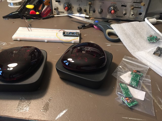
![]() 1.) I first decoded a random remote that the Beacon had in its list of devices. Those recorded values is what is used to tell the Attiny what code to send
1.) I first decoded a random remote that the Beacon had in its list of devices. Those recorded values is what is used to tell the Attiny what code to send -
2Step 2
![]() 2.) Cut Positive and negative lines from battery compartment
2.) Cut Positive and negative lines from battery compartment -
3Step 3
![]() 3.) Remove battery terminals
3.) Remove battery terminals-----------------------------------------------------------------------------------------
-
4Step 4
![]()
4.) Solder three wires to TSOP and enclose any exposed contacts
----------------------------------------------------------------------------------------------
-
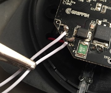
5Step 5
![]()
5.) Solder positive wire to V+ and negative wire to GND on Beacon
----------------------------------------------------------------------------------------------
-
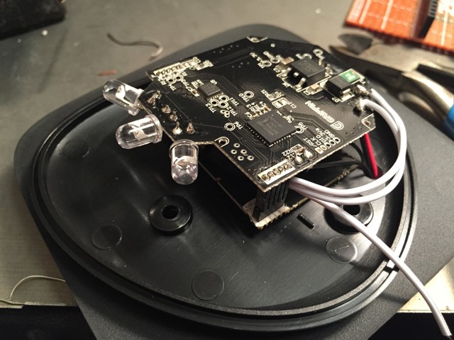
6Step 6
![]() 6.) Slide TSOP under the first board to avoid mounting screw holes
6.) Slide TSOP under the first board to avoid mounting screw holes--------------------------------------------------------------------------------------
-
7Step 7
![]() 7.) Snake the Data wire of TSOP through the hole that the power and ground wires go. Screw the bottom and cover back together.
7.) Snake the Data wire of TSOP through the hole that the power and ground wires go. Screw the bottom and cover back together. -
8Step 8
![]() 8.) The RF TX module i bought had a 90 degree pin header so I needed to resolder a straight header
8.) The RF TX module i bought had a 90 degree pin header so I needed to resolder a straight header -
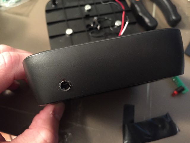
9Step 9
![]()
![]()
9.) Drill one hole for the USB power chord in the rear of the device and one hole in the front center for the indicator LED
-
10Step 10
![]()
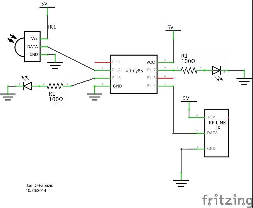
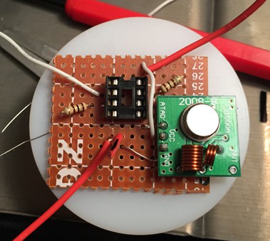
![]() 10.) Solder DIP socket, RF module, resistors and use wires as placements to connect the data line of the IR Receiver and LED
10.) Solder DIP socket, RF module, resistors and use wires as placements to connect the data line of the IR Receiver and LED
Ultimate Universal Remote
Improving a Griffin Beacon to add Bluetooth RF control, Command sequence sending and USB power
 1.) I first decoded a random remote that the Beacon had in its list of devices. Those recorded values is what is used to tell the Attiny what code to send
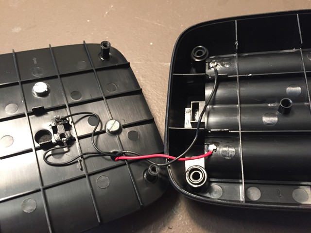 2.) Cut Positive and negative lines from battery compartment
 3.) Remove battery terminals
 6.) Slide TSOP under the first board to avoid mounting screw holes
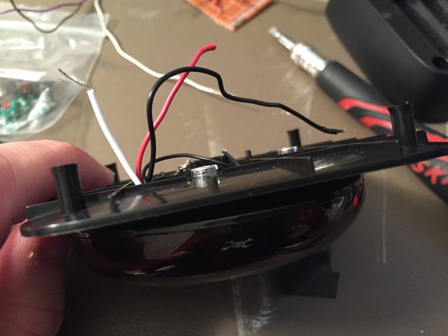 7.) Snake the Data wire of TSOP through the hole that the power and ground wires go. Screw the bottom and cover back together.
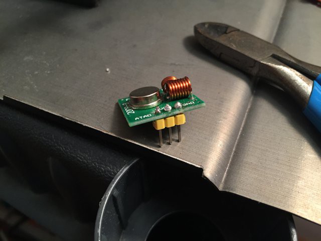 8.) The RF TX module i bought had a 90 degree pin header so I needed to resolder a straight header
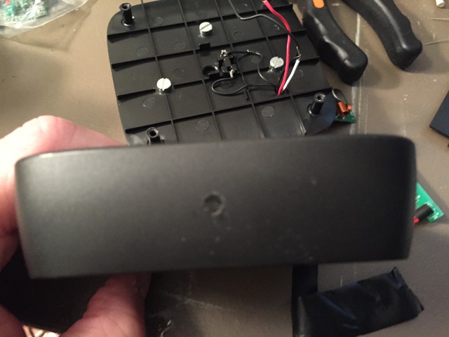
 10.) Solder DIP socket, RF module, resistors and use wires as placements to connect the data line of the IR Receiver and LED
Discussions
Become a Hackaday.io Member
Create an account to leave a comment. Already have an account? Log In.