 Ken Yap
-
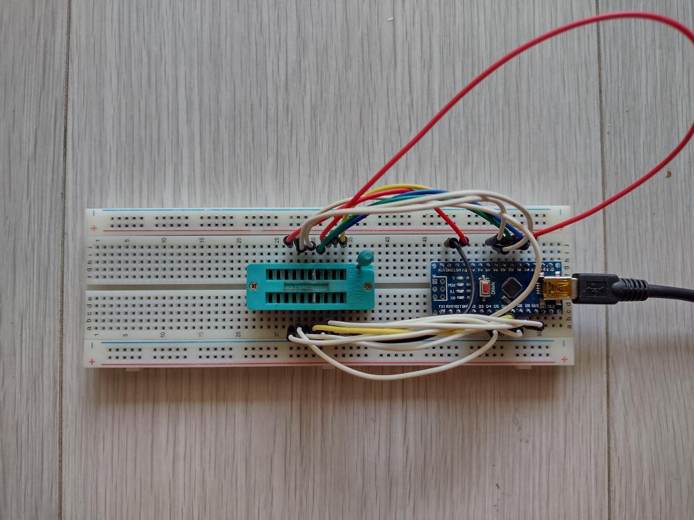
Flashing the CH552 dev board from the command line
a day ago • 0 commentsThis is a follow up to https://hackaday.io/page/13802-a-quick-foray-into-the-ch552-mcu
I finally got around to having a use for these cheap and tiny MCU boards.
Instead of using the Arduino CH55x framework by Deqing Sun in my initial exploration, I'm developing using command line tools. Editing and compiling using SDCC is no problem, I've done this for other 8051 projects such as #Adventures with a STC89C52 development board The issue is how to flash the embedded code to the board. The tool I chose is vnproch55x which is maintained by Deqing Sun also. So I just made a link to the binary provided by the Arduino CH55x framework.
However I ended up looking at the code on GitHub also to work out how to invoke it. From observing the output of the Sketch > Upload action, it's called with two additional command line parameters. The full invocation looks like this:
vnproch55x -r 16 -t CH552 blink.hexThe -r parameter sets the number of seconds to retry, the -t parameter chooses the target MCU type, and finally note that utility accepts hex files also, all enhancements to the original vnproch551 by NgoHungCuong. So if you don't have the Arduino CH55x framework installed, Deqing Sun's utility is the one to clone and compile to get an executable utility.
Also confusing the situation was that any sketch uploaded by the Arduino CH55x framework contains a bootloader which makes it appear as /dev/ttyACM0 which is a CDC with USB VID 1209:C550. This confused me because I was expecting the USB VID to be 4348:55E0. When such a CDC bootloader is in place you need to set the serial speed to 1200 baud and drop DTR to make it ready for receiving a sketch. The Arduino IDE does this but to do it from the CLI you can use a short Python script reset.py from the repo Arduino_Loader in GitHub. I made one small change to upgrade it to Python3 since that's the current Python on my Linux system.
However once you have loaded a bare metal sketch, i.e. one that doesn't use a CDC bootloader, it will appear at USB VID 4348:55E0. But I could not get the attention of the board to receive a new sketch. Remembering how similar boards work, I found the sequence.
- First start vnproch55x to read the hex file and start attempting to connect to the board. You now see why I used a generous retry period of 16 seconds.
- Connect the USB cable to the port while holding down the BOOT button (the other one is the RESET) button.
- Release the BOOT button. It will accept a USB connection and receive the code and execute it.
Great! Now I can finish the development of the embedded program and put the board to use.
-
A fugly amplifier
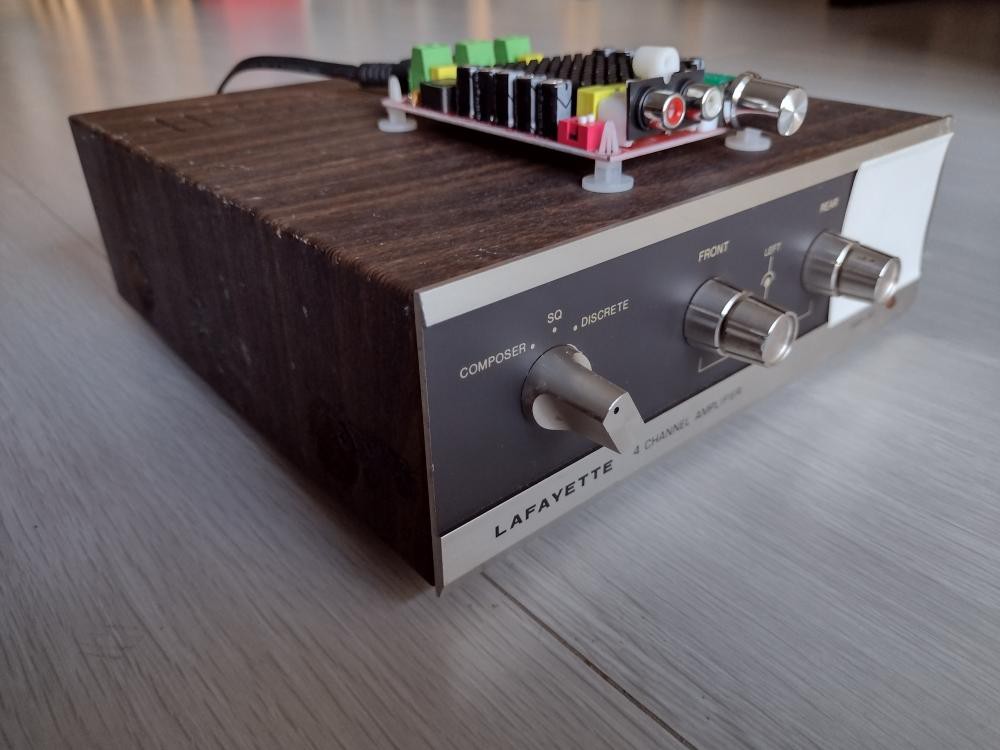
12/26/2023 at 08:09 • 0 comments![]()
My sturdy NAD amplifier developed a fault where the left channel got fainter and fainter. I have the service manual and I think I know where the fault is, but I haven't got a round tuit fixing it. Meanwhile I listen to music all the time so I would miss not having an amplifier. #Playing music remotely with bluetooth was partly a response to the deprivation.
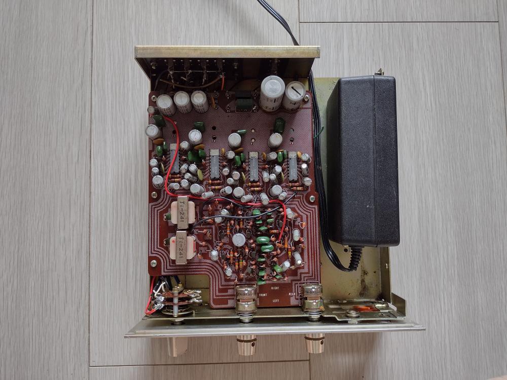
Knowing now that class D amplifiers are small, cheap and powerful, I thought I would buy another, more powerful, amplifier board and retrofit it to an old amplifier case. The amplifier you see came from some garage sale or other, I don't remember. I do remember that I bought it because it offered quadraphonic decoding. For a while in the late 70s, one could buy quadraphonic LP records that squeezed 4 channels onto the 2 channel groove of the vinyl. I had one or two such LPs and only ever heard them in stereo. But by the 2000s, multichannel digital recordings obsoleted the quadraphonic hacks. You can see the 4 power amplifier ICs in this top view of the amplifier.
![]()
I thought to put a SMPS inside the case and rewire the selector switch to choose between input sources. The amplifier board is totally disconnected and the volume pots do nothing. I only kept it because the volume pots are soldered on and removing them would leave even more holes in the front panel. (I may later take the pots off the PCB and remove the PCB, leaving the pots bolted on the case just for appearances' sake.)
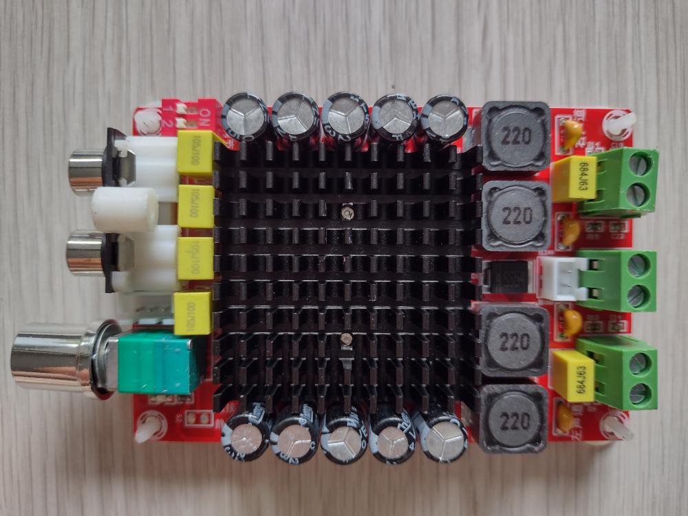
Here's the class D amplifier I bought for about $20 delivered. It takes up to 36V supply, and the SMPS which I think used to feed a laptop or something, can supply 32V. It's based on the TDA7498 chip.
![]()
So after a bit of of hacksawing and rewiring, I ended up with the fugly amplifier in the first photo. Fugly because the board is mounted on top of the case. To mount it inside I would have to think of some way to move the volume pot off the board.
Meanwhile I bought a modern AV receiver (not just a stereo amplifier, but multichannel, includes tuners, and even bluetooth input) on sale in the end of year offers so that does duty these days. I'll put this fugly hack to the back of my to do queue and get on with other projects.
-
Halving the execution time of an Arduino sketch
12/13/2023 at 08:04 • 0 commentsI have a large pile of 4164 and 41256 1-bit wide DRAM chips from the PC era. Many of them were extracted from sockets or boards. I was curious to know how many are faulty. A web search quickly turned up many designs for Arduino based DRAM testers. Most of them required only a few extra components in addition to an Uno or a Nano. Wiring is also simple so I wired up a tester on breadboard.
(There are complex versions that test a larger range of chips (e.g. additional voltage supplies), and have fancy features like an onboard display, but this was a one-off task. For the same reason I have no interest in any of the published PCB designs for Arduino shields.)
The first design I wired up was this:
![]()
This worked well. I didn't even wire up the LEDs because the serial console displays the status. Each chip takes about 80s to test. For succeeding chips I just have to press the reset button on the Nano as the program is already flashed into the MCU. It found a handful of faulty chips. Interesting that a batch of Mostek chips failed the test. Either their specs don't work with this tester, or a process fault ruined the chips over time.
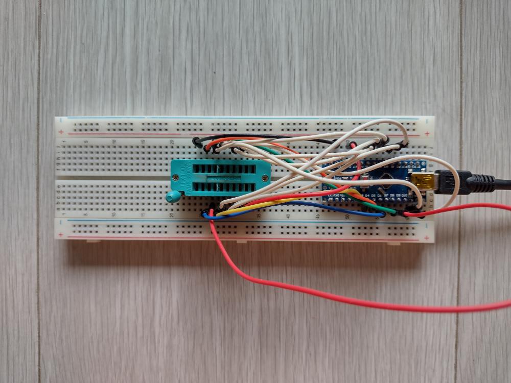
But this circuit didn't handle 41256 chips. So I turned to this design:
The wiring is different. Here they have tried to minimise wire crossings from each side of the Arduino to the chip socket, at the expense of a less logical pin assignment. But it doesn't matter since a table handles the mapping in the sketch.
![]()
This also worked well. But with 4 times as many bits the testing time ballooned out to 288s. This meant many minutes waiting. There is only so much surfing I can do on the computer while waiting for tests to complete.
Hacking the sketch
I know that the Arduino library digitalWrite() and digitalRead() routines do a lot behind the scenes and this is reflected in the execution time. The Arduino documentation shows how to do direct I/O on the ports, but discourages it because for most sketches it doesn't matter and the sketch loses readability and portability. But the same page acknowledges there are situations where direct access is warranted. This testing sketch is just such a situation; it does a lot of bit I/O.
So I looked into how to rewrite the sketch to use direct I/O. A goal is to not change the structure of the code but use conditional defines to replace the digitalWrite() and digitalRead() routines.
For digitalRead() on the data out pin there is only one instance that needs to be replaced with inline code to read the pin, so that is easy.
Since writing HIGH or LOW are different code sequences in direct I/O, we define separate macros for the two situations, called dWH and dWL. When the optimisation is disabled, these map to digitalWrite(port, HIGH-or-LOW) and the program runs as before. When optimisation is enabled, these are defined as routines dWH() and dWL(). They use a switch statement to direct to the appropriate code for that pin. To discover the appropriate direct I/O statement one needs to consult the pin table of the Nano. The pins are also labelled in the sketch comments. So the overhead of direct I/O on a pin is a call, switch, and return.
Not all the digitalWrite() calls need to be substituted. Those dealing with the LEDs are not time critical and can be left as-is.
#define FAST_RW

#ifndef FAST_RW

#define dR_DO() digitalRead(DO)
#define dWH(p)  digitalWrite((p),HIGH)
#define dWL(p)  digitalWrite((p),LOW)

#else

#define dR_DO() (PINB & 1)

void dWH(int p) {
    switch (p) {
    case XA1:
        PORTD |= (1 << 2); break;
    case XA7:
        PORTD |= (1 << 3); break;
    case XA5:
        PORTD |= (1 << 4); break;
    case XA4:
        PORTD |= (1 << 5); break;
    case XA3:
        PORTD |= (1 << 6); break;
    case XA6:
        PORTD |= (1 << 7); break;
    case CAS:
        PORTB |= (1 << 1); break;
    case XA8:
        PORTC |= (1 << 0); break;
    case DI:
        PORTC |= (1 << 1); break;
    case WE:
        PORTC |= (1 << 2); break;
    case RAS:
        PORTC |= (1 << 3); break;
    case XA0:
        PORTC |= (1 << 4); break;
    case XA2:
        PORTC |= (1 << 5); break...
Read more »
My Pages
Projects I Like & Follow
 Anders Nielsen
 Guy Dupont
 Stefan Wagner
 Keri Szafir
 Anders Dinsen
 Just4Fun
 Alan Boris
 biemster
 doctek
 Kevin Santo Cappuccio
 Jacques Pelletier
 Dan Julio
 yjmwxwx
 CanHobby.ca
 Frederico Souza Sant'ana
 Jay Riedl
 Walter
Share this profile
ShareBits


Thank you for following my Sol-20 Reproduction project Ken.

Hi Ken, thanks for the like for my TD4.
As far as a CPU it is pretty useless but it makes a great demo because of the flashing LEDs.
This seems to be a Japanese trait. When I was in Japan even the vending machines had animations. The TD4 book is half electronics and half anime imagery.
I am looking a more powerful 4 bit CPU in the same style as the TD4 (but for the prototype, using an IC PROM rather than a diode PROM). Only pencil drawings on graph paper at the moment.
Regards AlanX

A CPU with 11 TTL packages is interesting because I probably have all the parts needed but pity it doesn't do much more than flash LEDs. Looking forward to seeing your design.
Hi Ken,
I had a re-look at the TD4 and I had design a Paged version (https://cdn.hackaday.io/images/1250221502460302068.png) that increased the program space to 256x8. An ALU can be mapped in RAM space (16x4) but I did not pursue that option further (I could see better options).
Also an ALU (say an 181) could be connected to the A and B registers as inputs and the output directed to the "Zero Port". That is, replace "Move A,Z+Imm" with "Move A,ALU+Imm" etc. The Page register could be used as a function register for the ALU. The ALU would need to output Zero upon reset and to return to Zero under program control. Such is the problem with 4 bits is that you need more OpCode space.
Finally you could replace the original adder with an ALU and control the function with the Page register. You would need to be careful to be able to recover the CPU from a lock state. It was at this point I decided to build a new 4 Bit CPU from scratch.
Regards AlanX
Hi Ken,
I completely forgot, I have a redesigned TD4B version of the board (based on the one shown in my project posts: https://cdn.hackaday.io/images/5564921527557781106.png) but without the RAM and tidied up. It has not been tested (one day I will assemble it) but it should work. PM me if you want one.
AlanX
Thanks @agp.cooper
I'll think start small, with a zero bit CPU, just like I started learning juggling with zero balls. TBH I haven't progressed beyond that point. 🤣
Thank you for your comment to my #PERSEUS-8 homemade 6502 computer !
Thank you for liking my #Homemade Operational Amplifier and your comment !

Hi Ken, thanks for the like!
You've got a couple of nice projects, and I like your motto. Tinkering with electronics can be meditation.
Hello Ken, thanks for liking and following my new project, the Kobold computer, https://hackaday.io/project/164897-kobold-retro-ttl-computer !
Yes, obviously like me you appreciated the cleverness of the PDP-11 instruction set where the PC being R7, load immediate becomes load indirect R7 with autoincrement.
Thank you for liking and following my #Prehistory of my homemade PERSEUS computers !