When I started working on the new design around Christmas last year the first part I bought was a portafilter coffee machine pump with a high flow and pressure rating.
My initial idea was to use only one single pump for moving all fluid in the system and use a venturi nozzle to generate the needed vacuum for the return line and makeup/solvent loading.
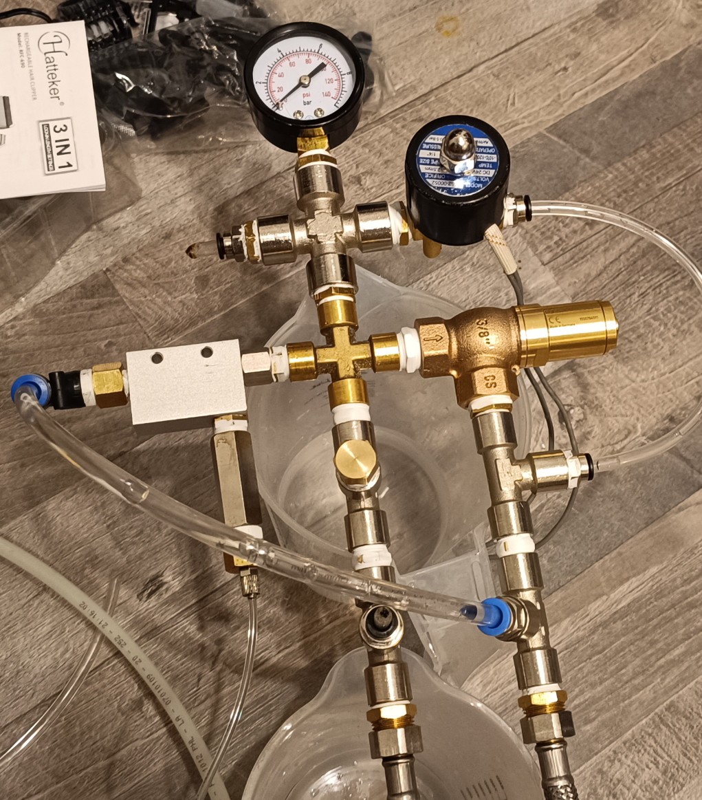
Venturi Valve and Pressure Pump
While it worked well with water and pure ethanol, more and more problems arose as the viscosity increased.
With the high-viscosity ethanol + PVB mixture that I want to use for printing, the venturi valve injected a lot of small bubbles at a high rate into the mixture creating a layer of foam on top of it which kept on rising until the ink tank started foaming over. At the same time, the small bubbles got sucked into the pump causing it to run unstable which would damage the pump over time while creating a loud unhealthy sounding noise.
Foam on the Ink
Over the last weeks, I tried a few things to reduce the foaming problem, but nothing of it could solve it completely...
Small Bubbles mixed with Ink
Another problem with this design was that while the venturi nozzle could still generate a high-flow suction when powered by a high-viscosity fluid, the vacuum level got reduced so much that it could no longer draw in the fluid through the return line...
While this wasn't already bad enough the pump also generated a lot of heat which makes it hard to keep the temperature inside the system constant...
With these problems and the fact that these kinds of pumps are pretty noisy and also quite expensive when bought new, it was time to start working on a better and cheaper solution.
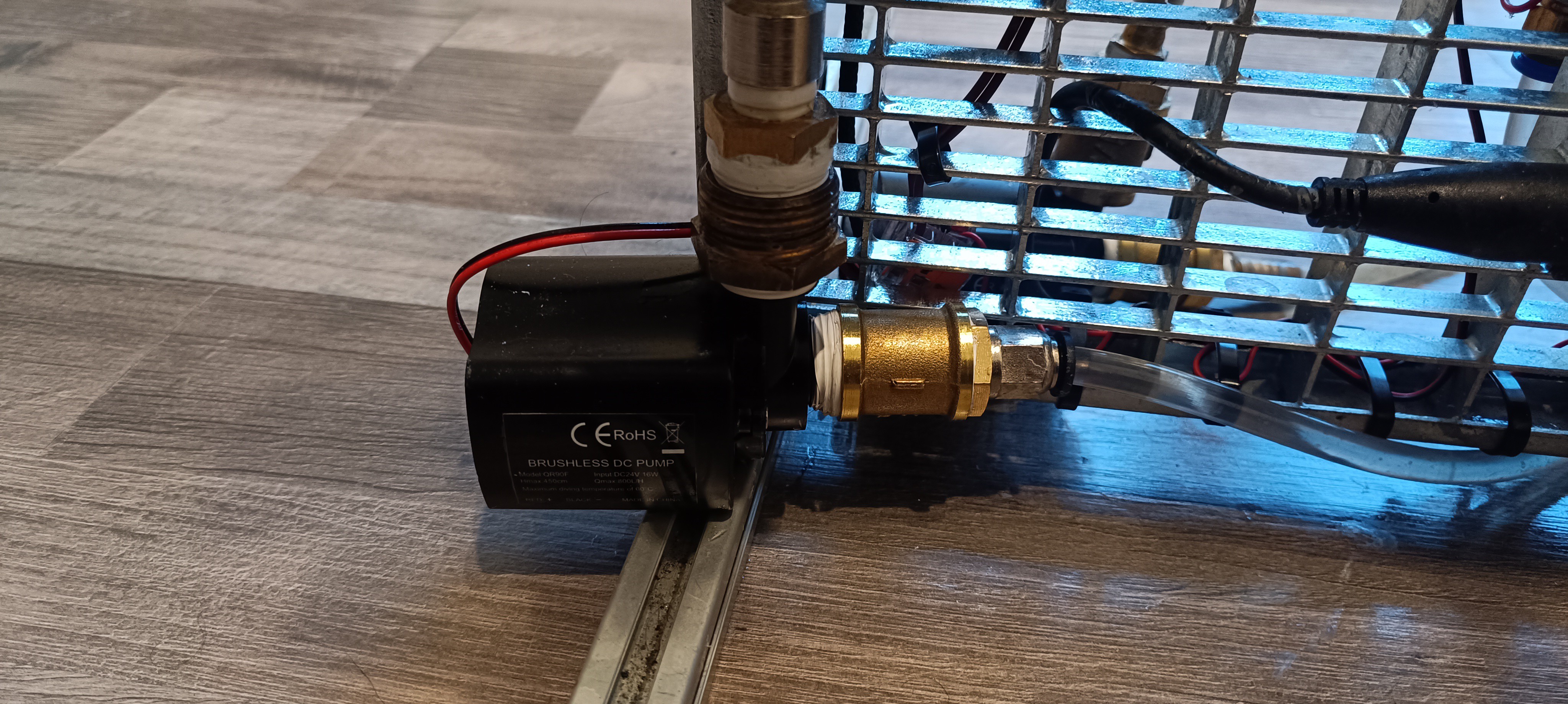
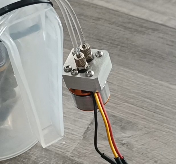
Brushless DC Pump for Ink Circulation
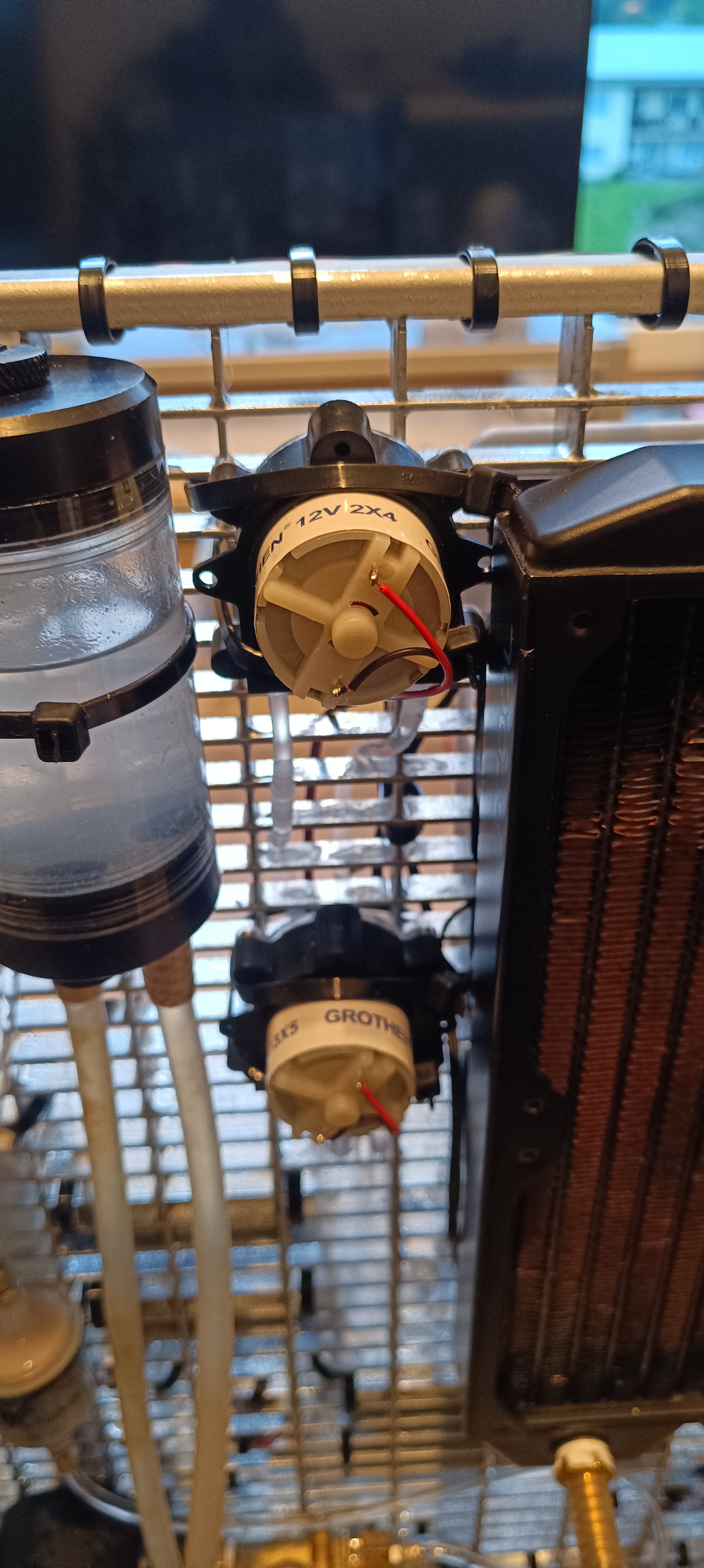
A few weeks ago I already added two small 24V brushless pumps to the printer for ink circulation inside the viscosimeter and for water cooling.
While thinking about the changes needed for replacing the large pump I realized that the viscosimeter circulation pump can also be used for circulating all the ink inside the printer and not only the ink inside the viscosimeter. Because of that I could remove the valves needed for the "viscosimeter sample refresh" function and just keep the pump circulating the ink all the time.
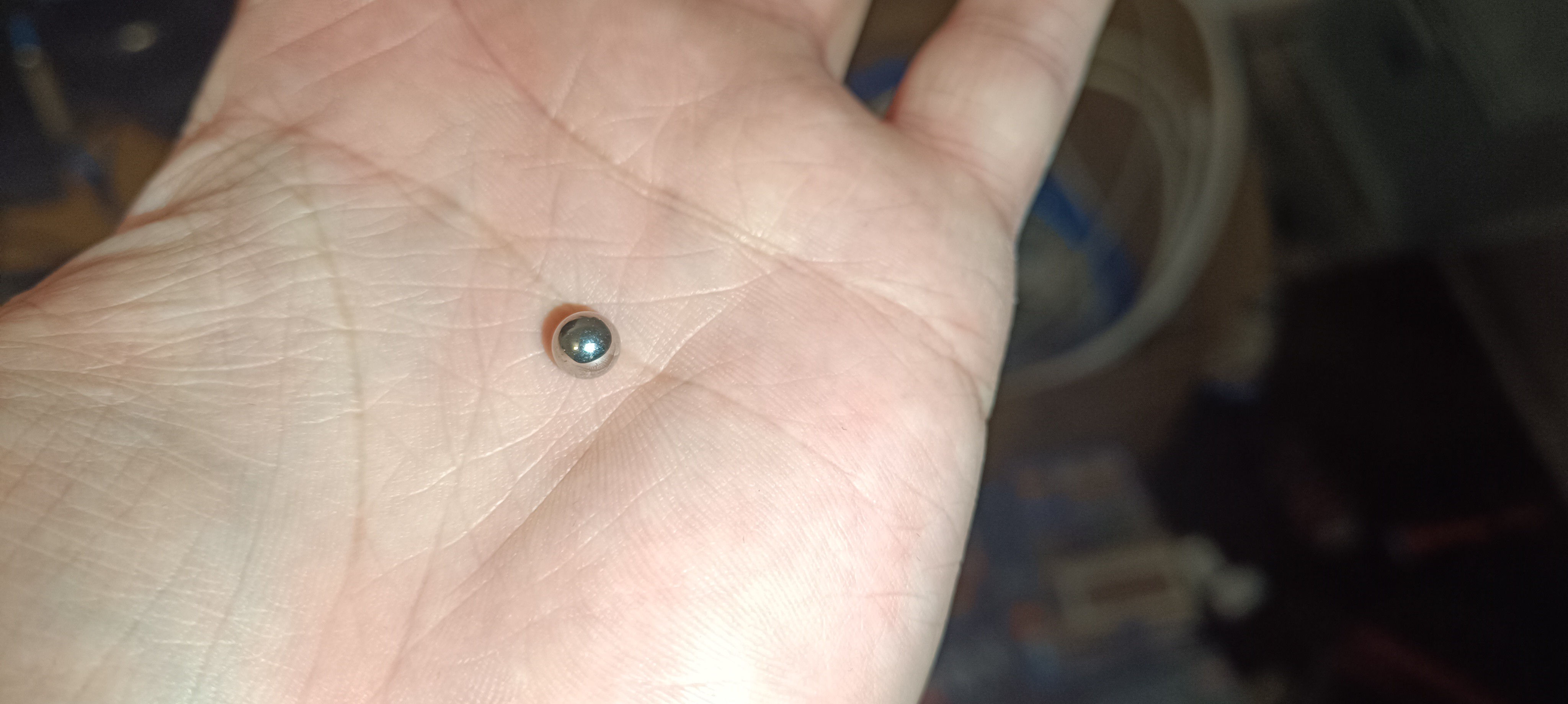
For lifting the steel ball inside the viscosimeter a solenoid valve connected parallel to the pump outlet can be opened from time to time.
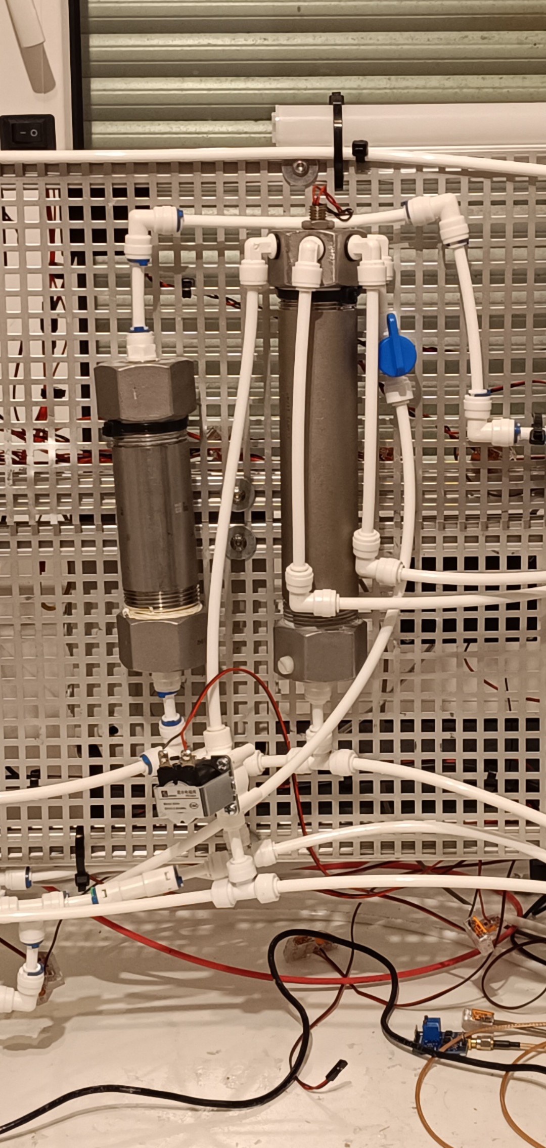
The ink flows from the ink tank to the circulation pump and gets pumped to the viscosimeter.
Outlet of the Ink Tank
Ink Circulation Pump
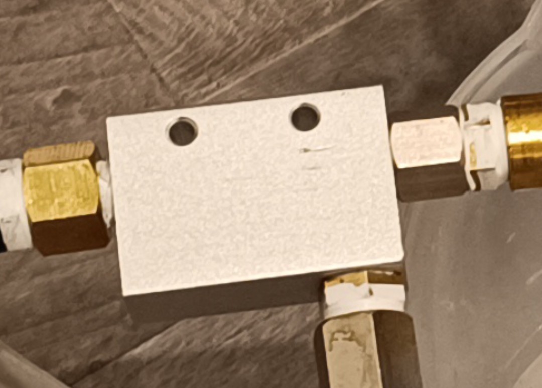
From there it flows into a T fitting which is connected to the outlet of the relief valve that regulates the pressure of the pressurized part of the system.
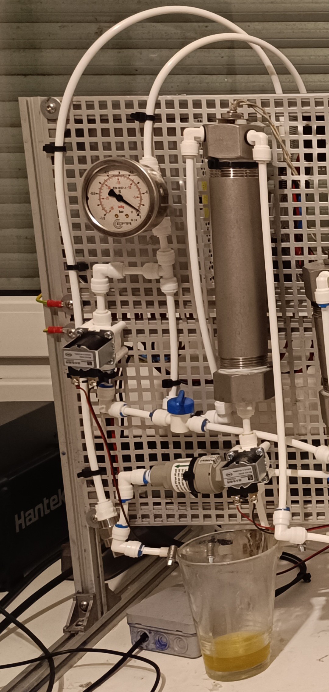
Viscosimeter
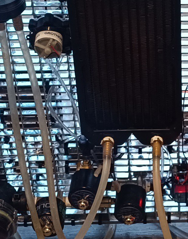
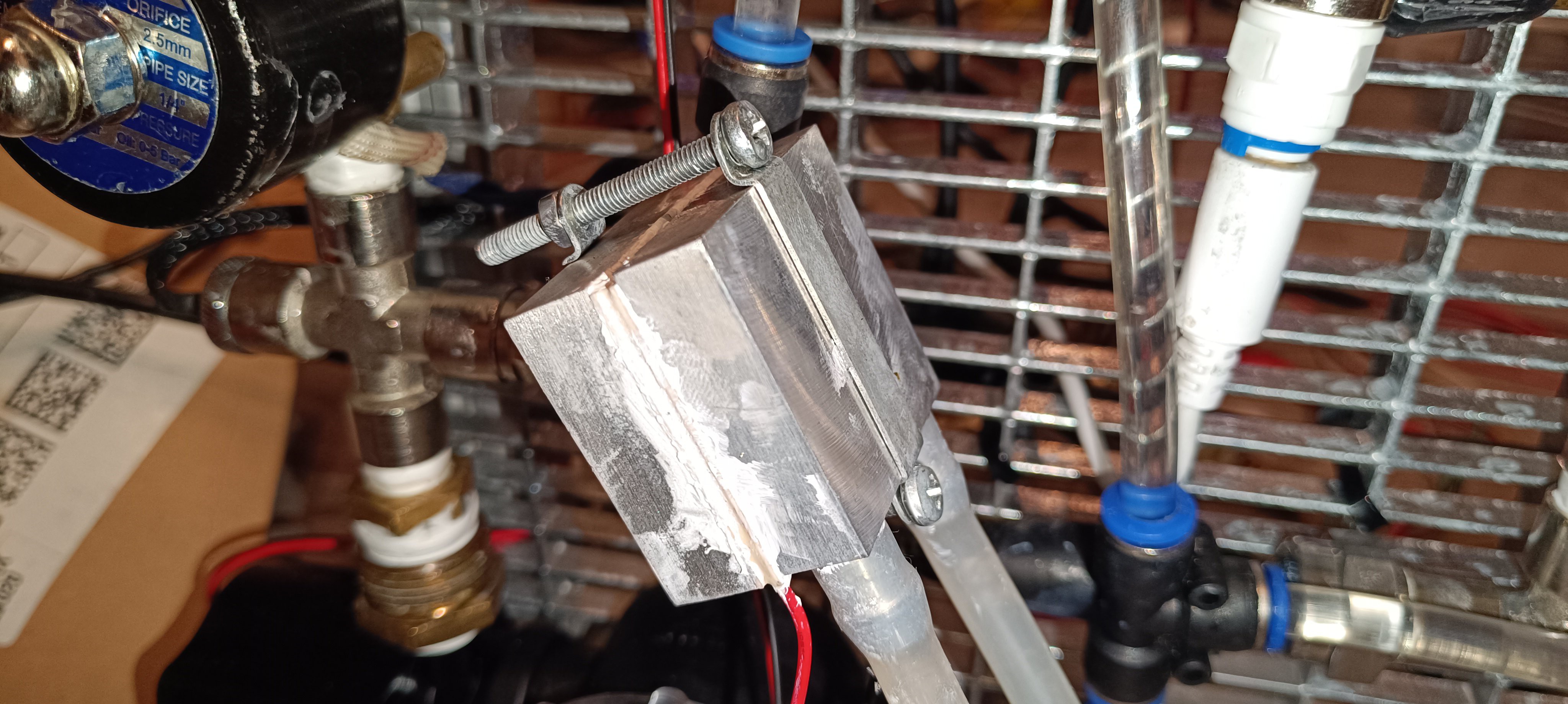
From there the ink flows into the heat exchanger that keeps the ink at 25⁰C by heating and cooling it.
Heat Exchanger
Finally, the ink enters the ink tank again to complete the cycle that keeps the ink well-mixed and at a steady temperature.
Inlet of the Ink Tank
Brushless DC Pump for Water Cooling
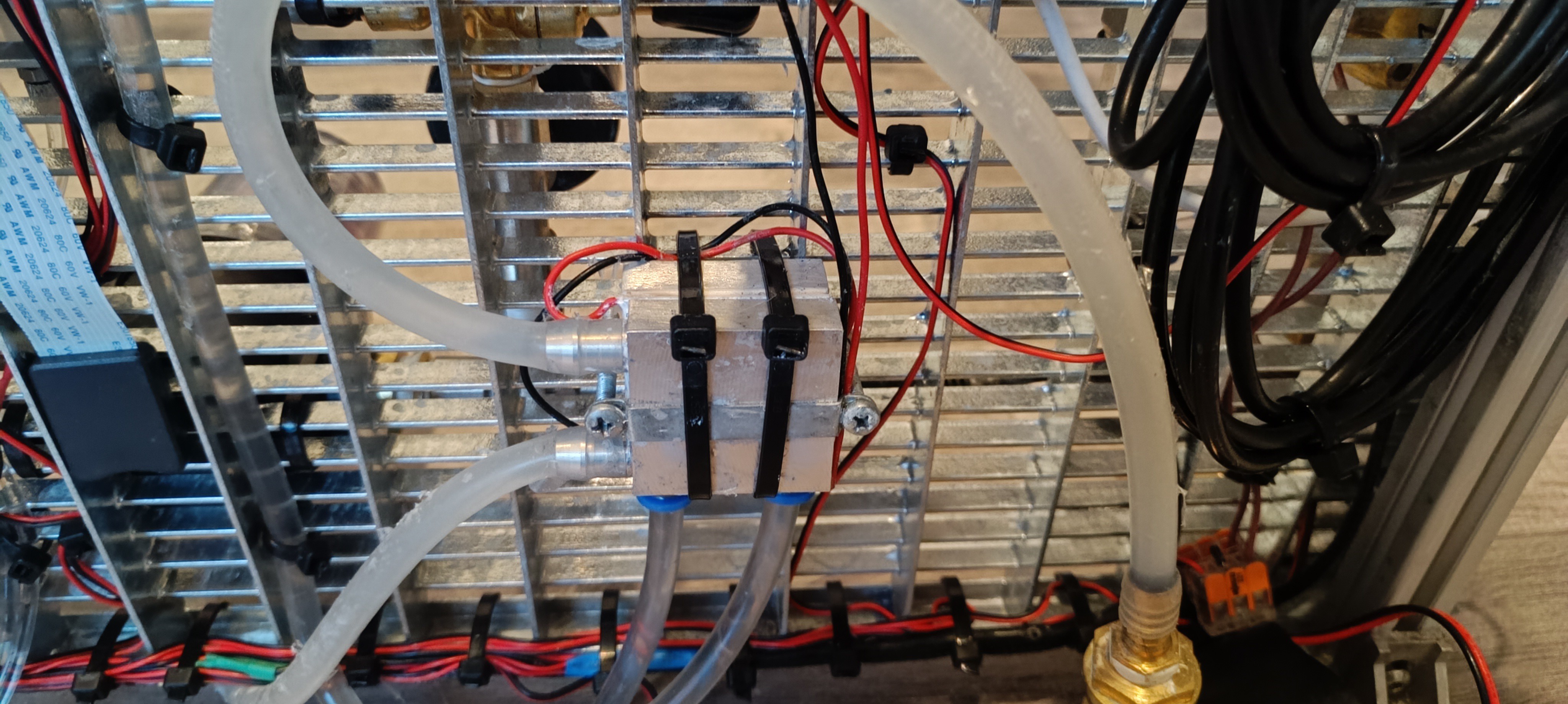
The water cooling system is used for cooling a TEC 12706 Peltier module for heating up or cooling down the ink so that it can be kept always at 25⁰C independent from the room temperature.
The water flows from the water reservoir tank to the circulation pump and gets pumped into the heat exchanger.
Water Cooling Pump
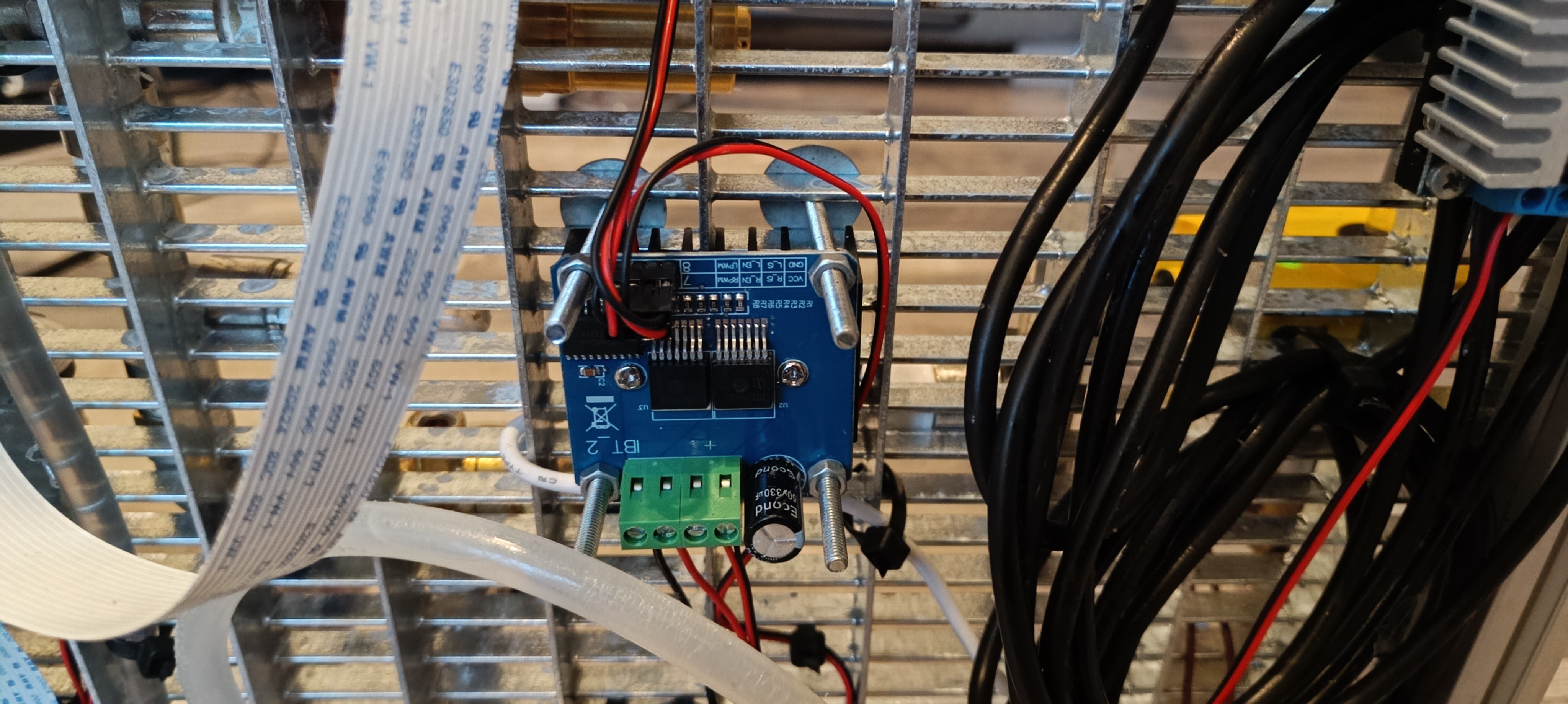
Heat ExchangerThe Peltier module is driven by a BTS7960 H-Bridge module so that it can be used for cooling and heating as well.
BTS7960 H-BridgeThe H-Bridge is powered by an XL4016 step-down converter module which outputs 12V.
XL4016 Step Down ConverterFrom the heat exchanger, the water flows into the radiator and from there it flows into the water reservoir tank to complete the water cooling cycle.
Radiator and Water Reservoir Tank
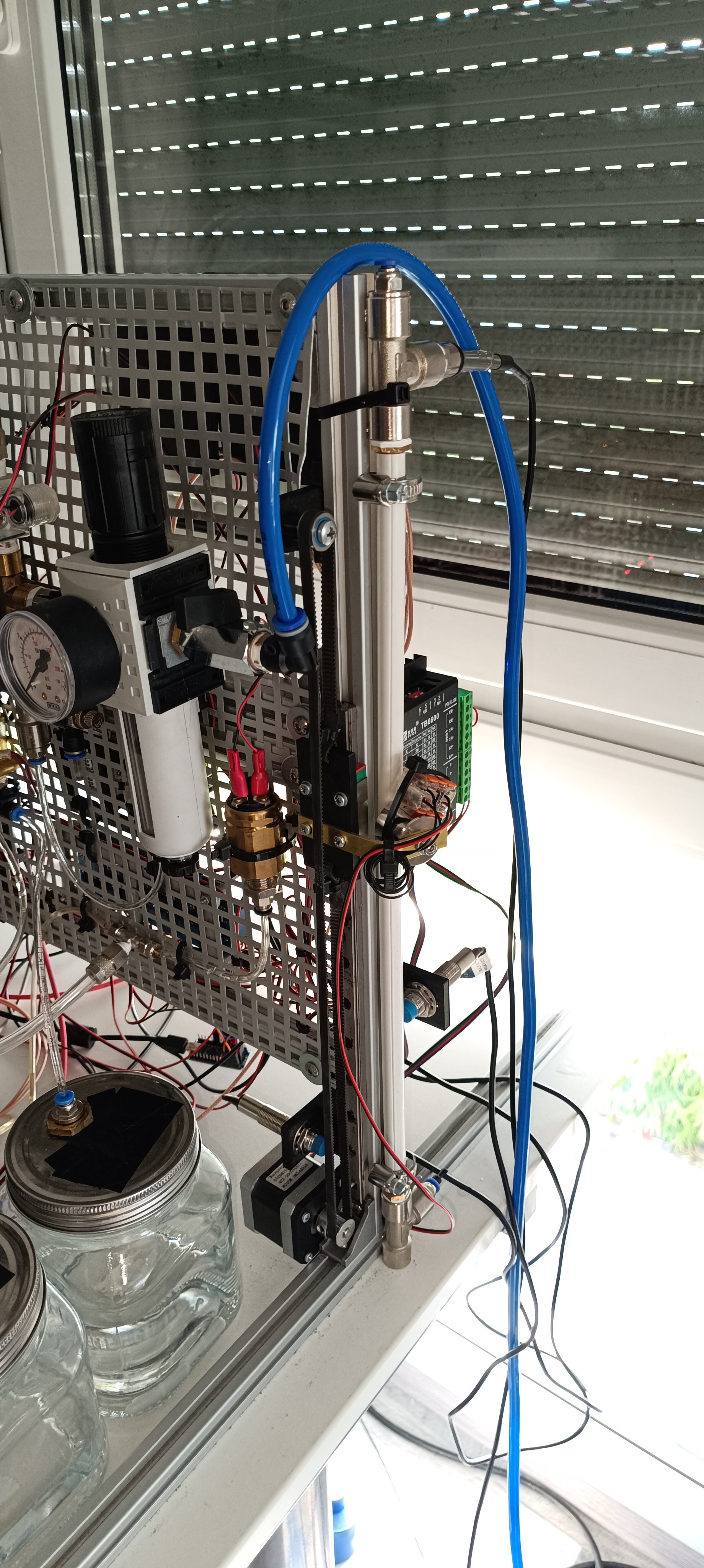
Peristaltic Pump for Solvent/MakeUp
For adding solvent/makeup (ethanol) to the mix I switched to using a peristaltic pump instead of the vacuum line. This pump should be able to add always the same amount of ethanol to the mix when running at the same speed for the same amount of time.
Peristaltic Pumps
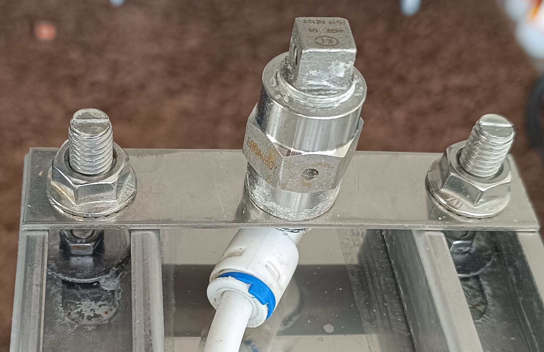
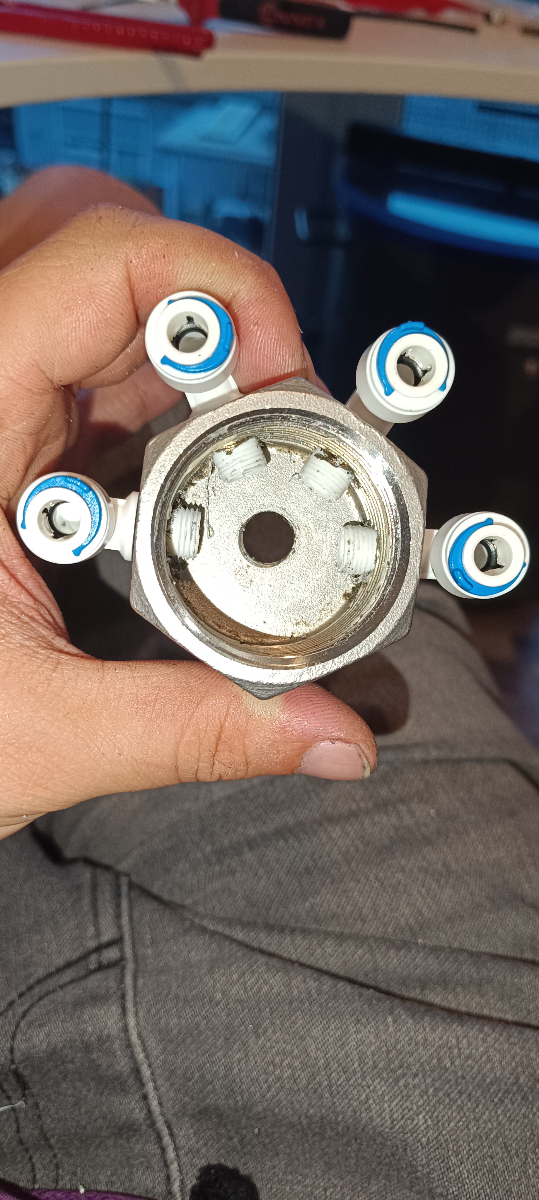
The ethanol is drawn from the bottle next to the tank and flows from the pump into the cross-fitting at the top of the tank.
The side connections of the cross-fitting are for makeup and return line and the top connection is for adding pre-mixed Ethanol/PVB ink and venting the air from the return line out.
A quick note here:
While writing this project log I just had the idea to relocate the two valves on the printhead over to the machine frame.
These valves are used for applying the vacuum either to the nozzle or to the gutter.
Two Valves on the Printhead
At the moment the printhead is mostly disassembled and only used for testing the fluid lines.
When everything related to fluid management is working nicely and reliably, I will build a separate prototype only for the printing electronics to ultimately merge both parts into another revision of the project.
Since this is the most complicated project I ever worked on, it will still take a long time until it can be used for anything useful.
Printhead without ValvesNew Location of the Valves
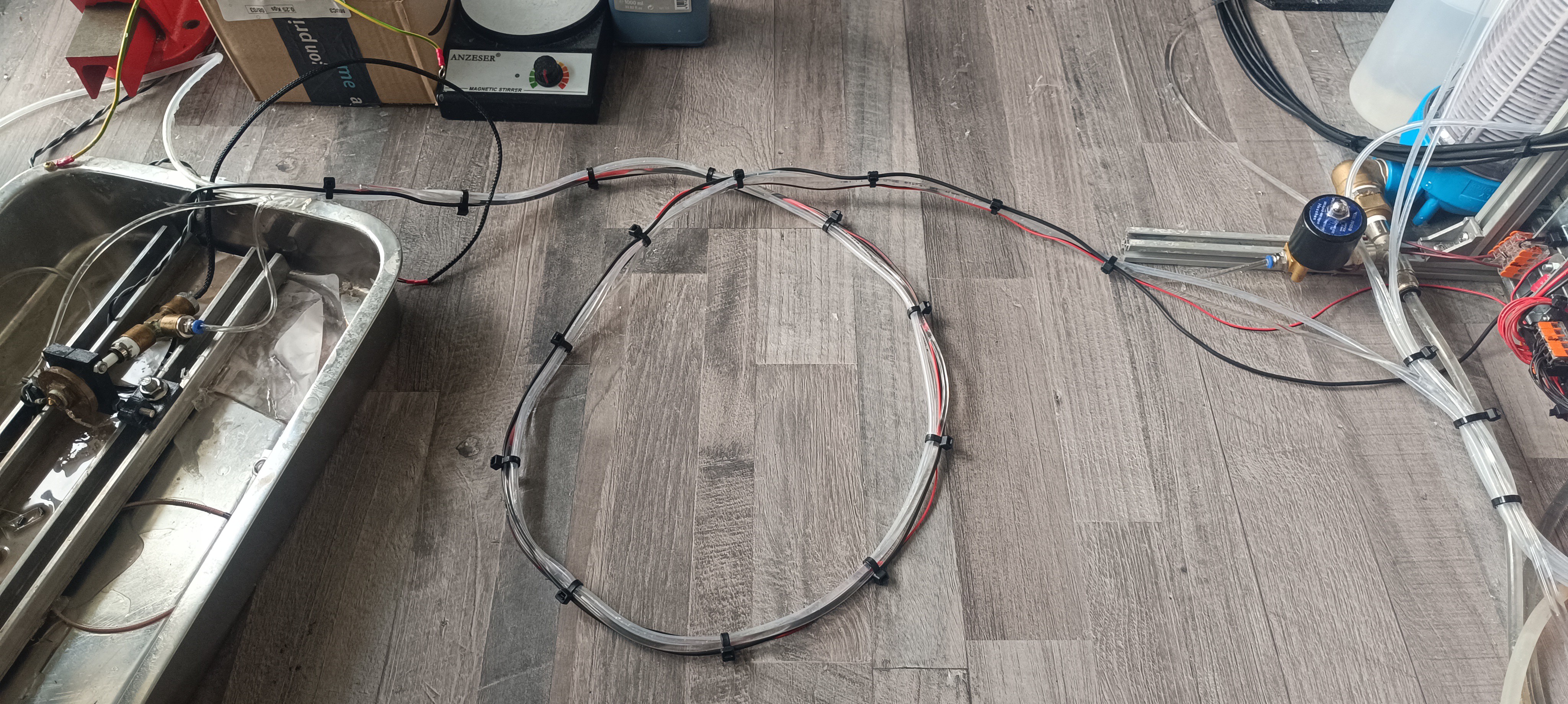
Currently, the printhead is connected to the printer via a 3m long connection line consisting of a ground wire for ESD protection, a cable connection to the nozzle thermistor that checks the ink temperature at the nozzle, the ink line which supplies pressurized ink or vacuum for cleaning to the nozzle, the return line which draws the ink back to the printer and a flush line which is connected to the ink tank that can be used for flushing the nozzle line and return line by applying vacuum to the line that needs to be flushed and connecting the flush line to this line. The vacuum draws the ink from the tank through the line that should be flushed to the peristaltic pump and from the pump back into the ink tank which has a mesh filter inside for separating any dirt that may get flushed out of the line.
3m long Connection Line to the Printhead
Peristaltic Pump for the Return Line
When I tested out the first peristaltic pump for adding makeup, I was surprised at how well these pumps can generate suction.
The generated vacuum level is higher than that of the venturi nozzle when driven with high viscosity fluid and the flow is much lower so that not as much air gets sucked in that could mix with the ink to form bubbles or foam.
Replacing the venturi with a peristaltic pump has not only the advantage that it solves the bubble/foam problem, it also lowers the required high-pressure flow rate, because now, without the venturi nozzle, the only thing on the printer that requires high pressure is the ink stream through the 0.1mm nozzle which only requires a very low flow rate what makes it possible to use other types of pressure pumps for the printer.
The return pump pumps the ink back into the cross-fitting on top of the ink tank which generates a vacuum on the input side of the pump that is used for either returning the ink from the gutter or cleaning the nozzle.
For returning the ink from the gutter, the gutter valve is opened so that the ink from the ink stream hitting the gutter block/pipe can be drawn back into the printer. This is normally done as long as the printer is active and the ink stream is present.
For returning the ink from the nozzle, the gutter valve is closed and the nozzle vacuum valve is opened, so that the ink can flow backward through the ink line via the return line back into the tank. This is normally done to clean the nozzle with either pure ethanol or ink from the flush tube.
While only a small amount of pure ethanol should enter the system to not dilute the ink too much, the flush tube can be used as long as needed for flushing particles out of the nozzle/ink line that may block the nozzle again if they don't get completely flushed out of the ink line.
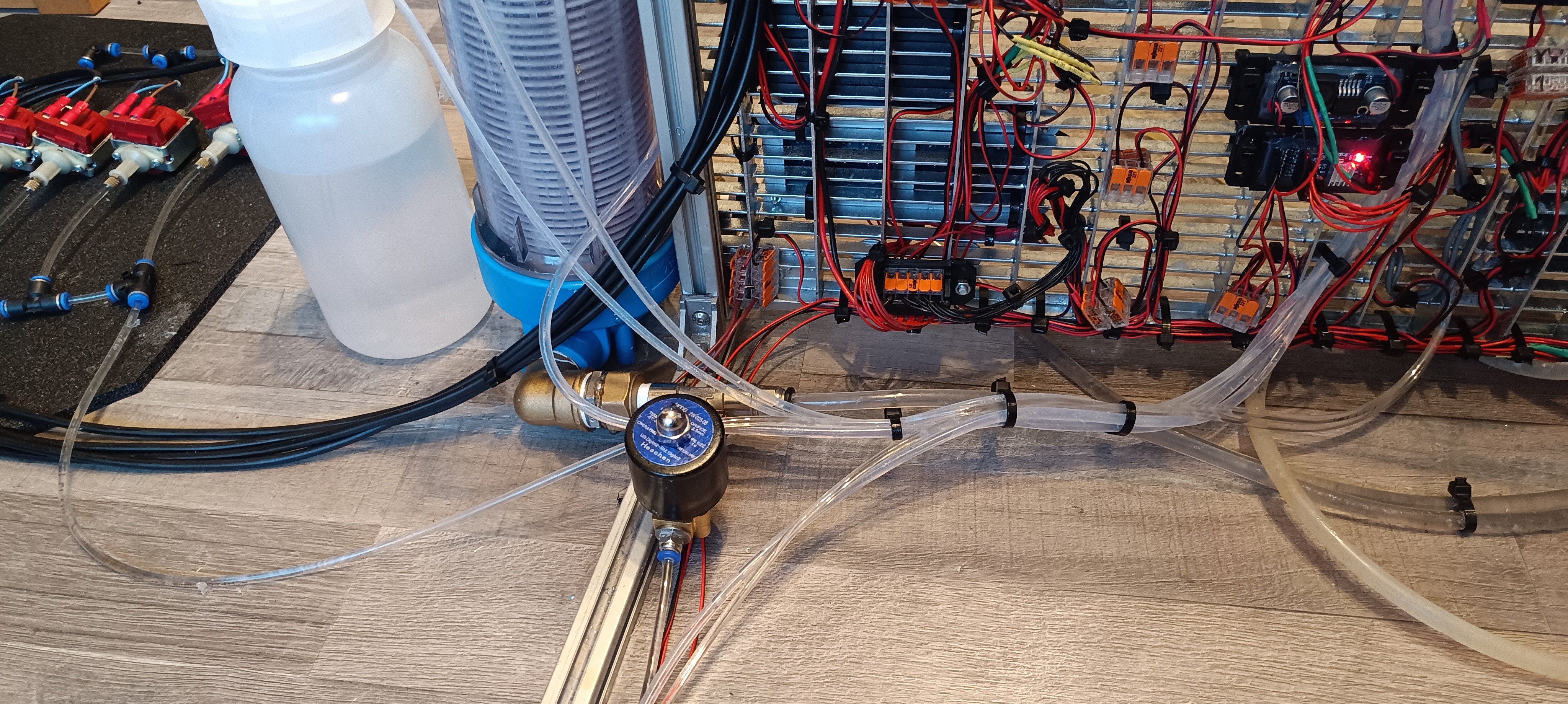
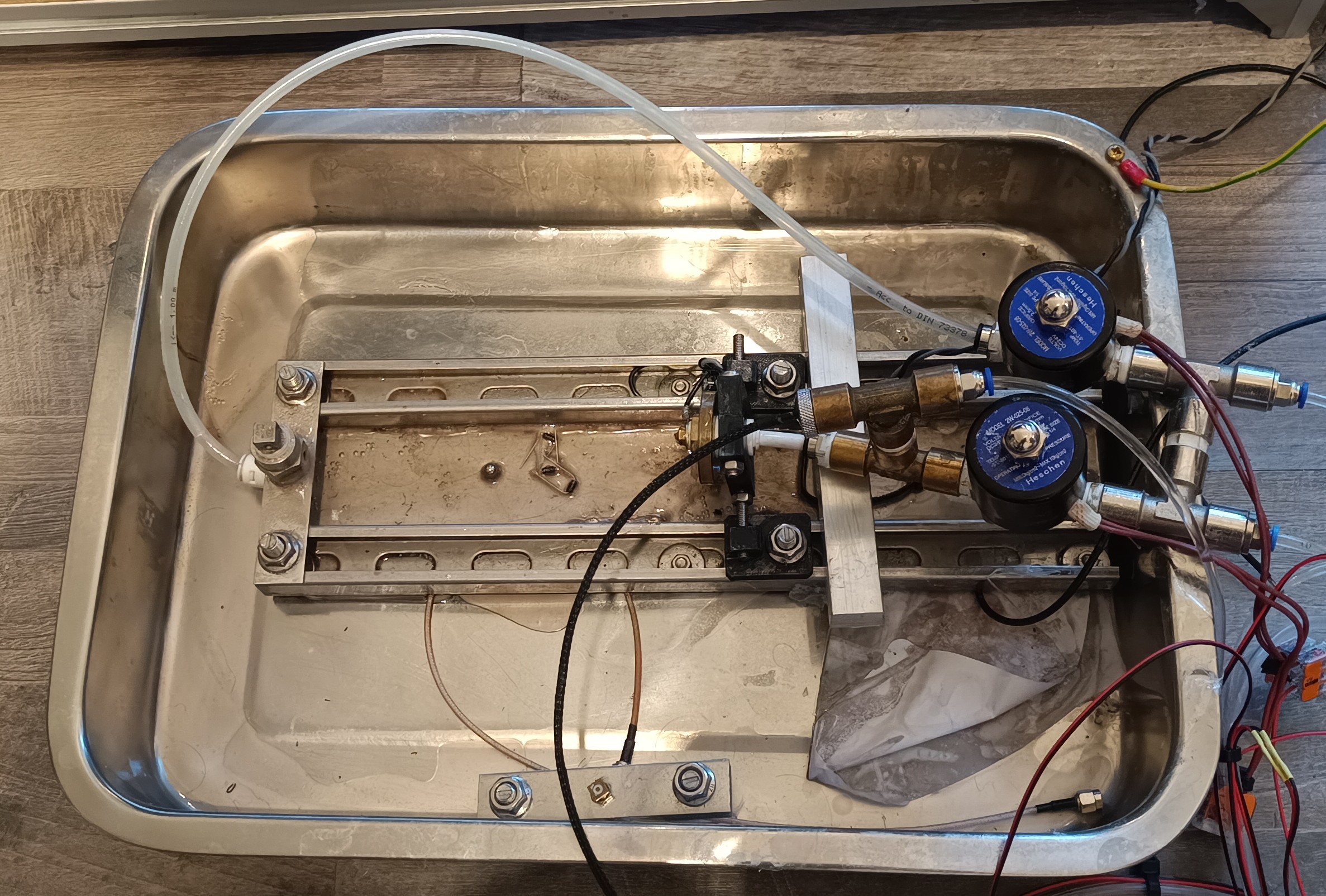
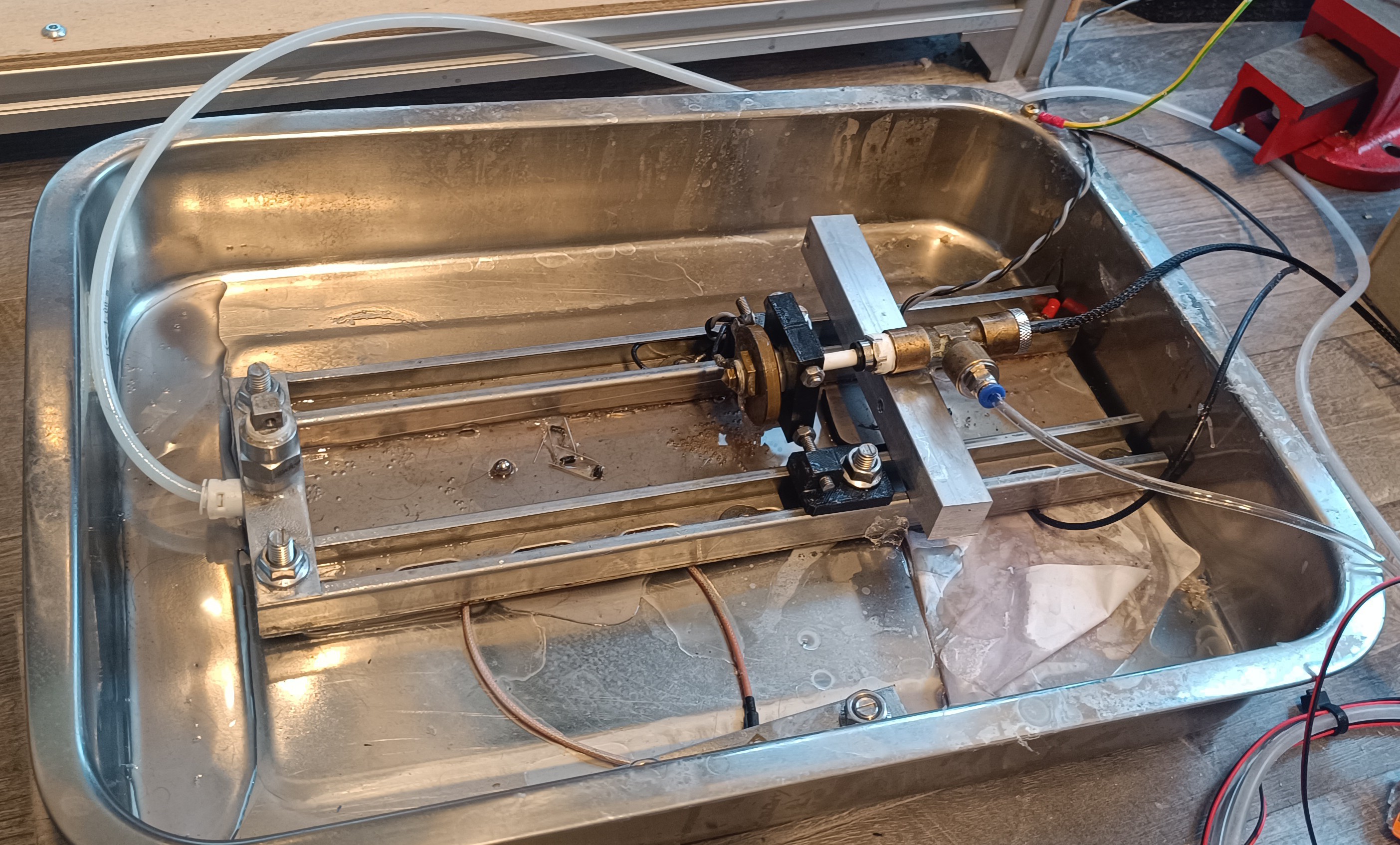
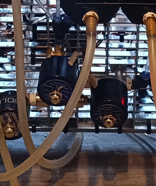
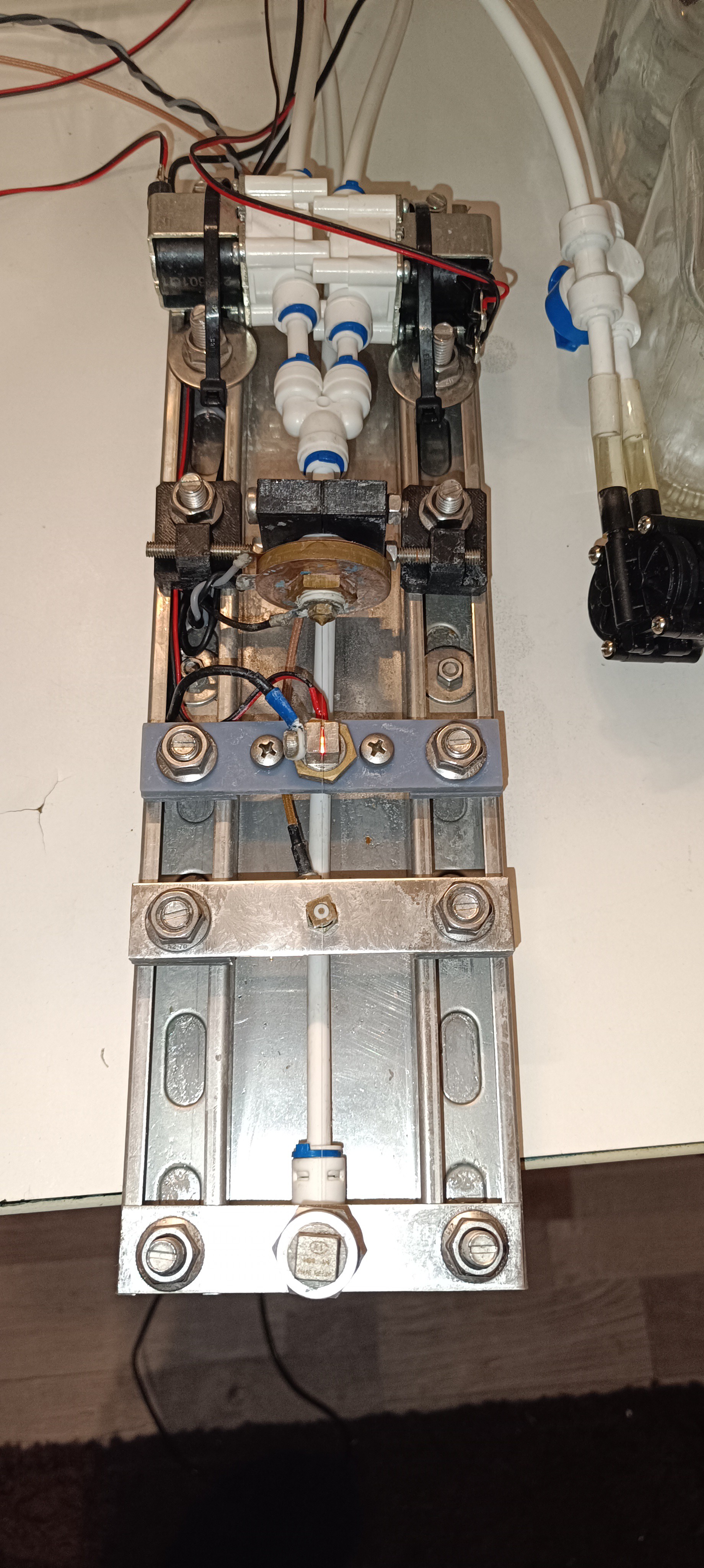
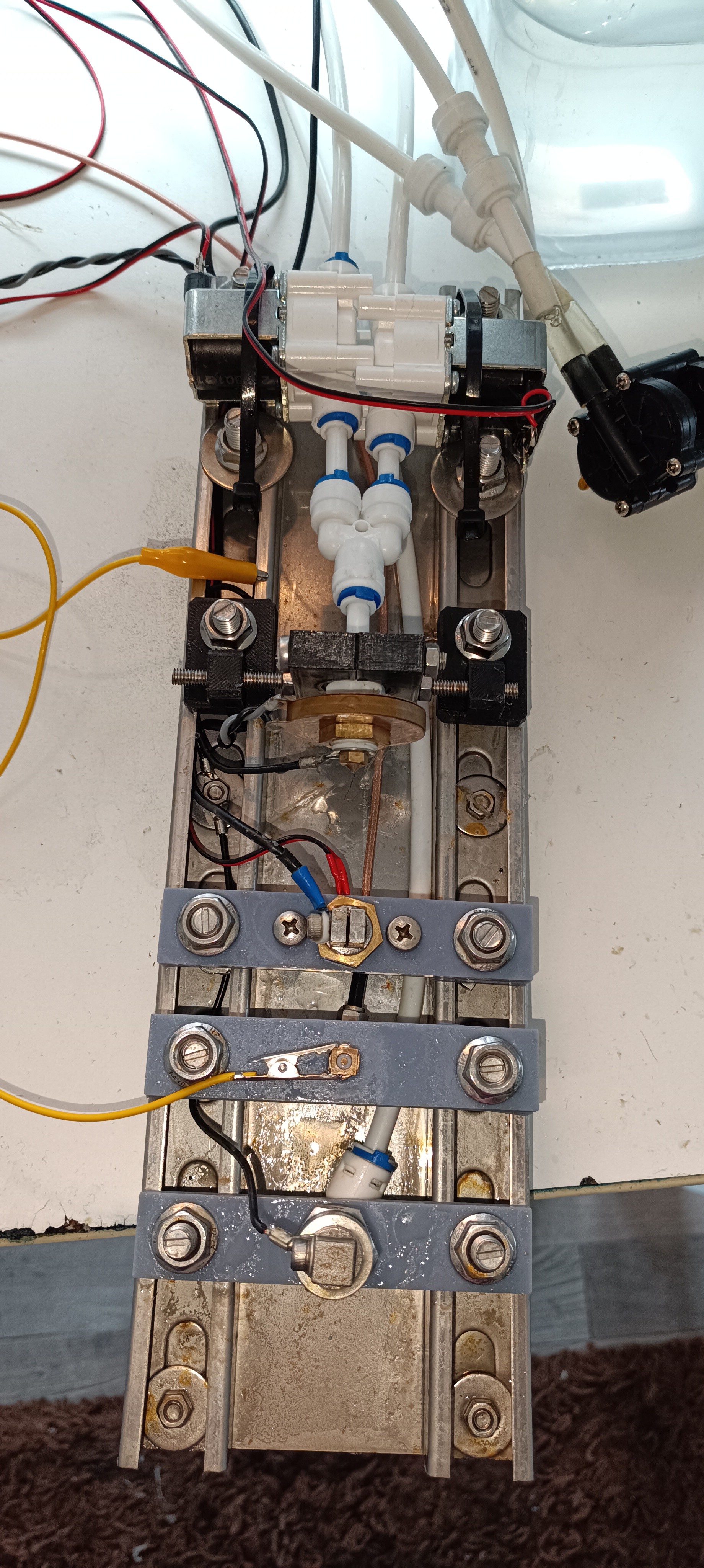
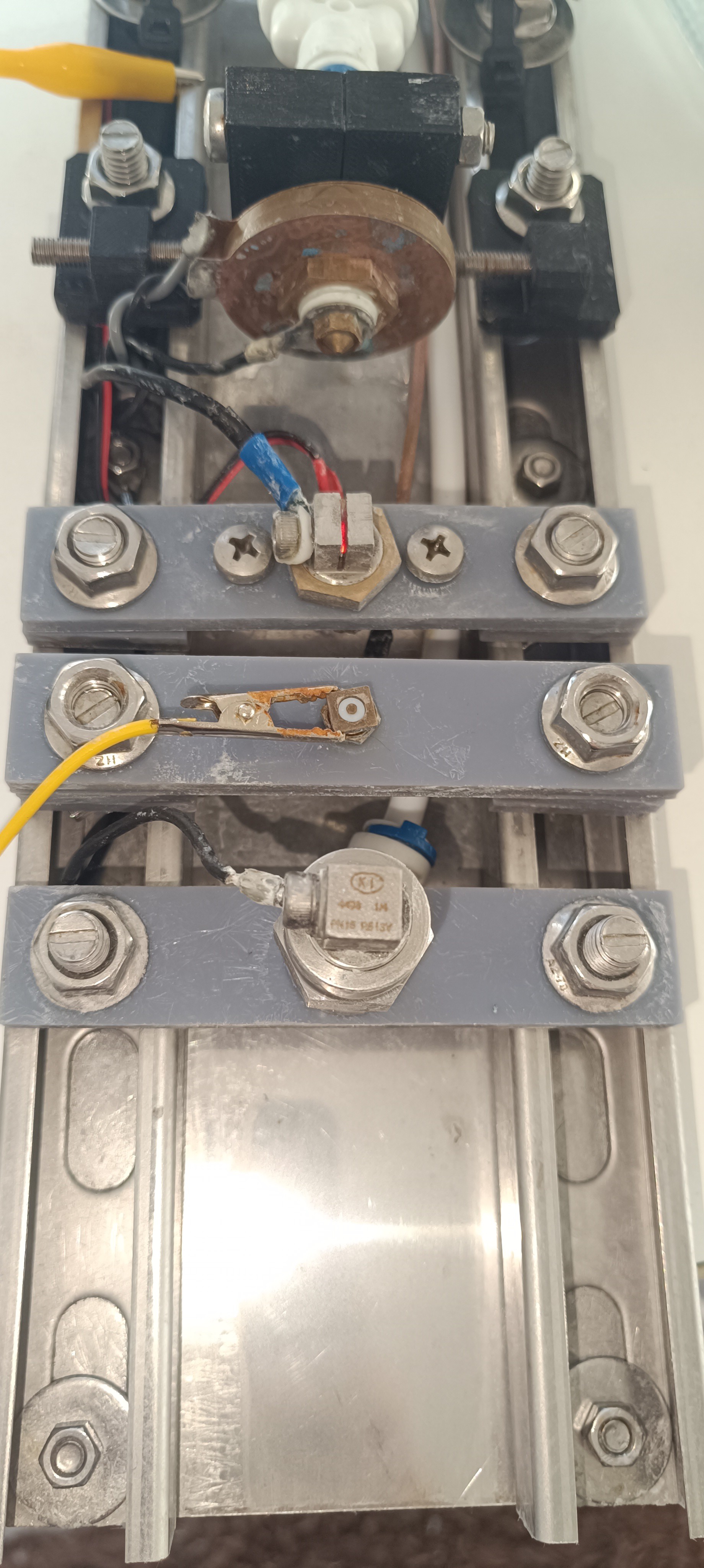
New Pressure Pumps: 4 Solenoid Pumps
Since the high-pressure flow requirement got much lower with the new design, it is now possible to use other pressure pump types for generating the needed pressure and because small solenoid pumps like the ones used in cheap coffee and fog machines don't make a lot of noise, I decided to use them for generating the needed pressure.
These pumps are available in many different sizes with different flow, pressure, and power ratings. While the smaller ones are very quiet, the larger ones make a louder humming noise.
While some models can run at 100% duty cycle, most of them are only rated for running in 1 min on / 1 min off cycles to prevent them from overheating. This is the major drawback of this kind of pump.
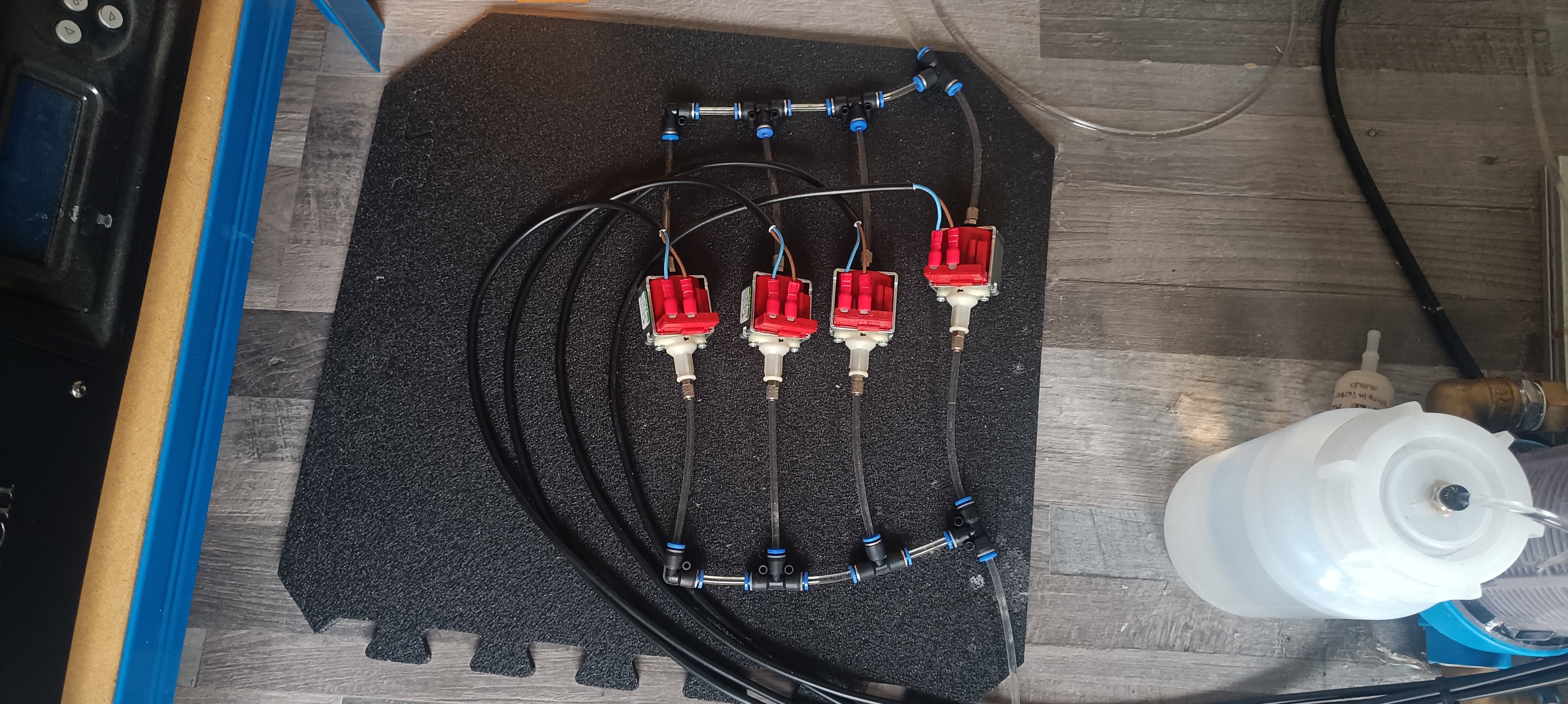
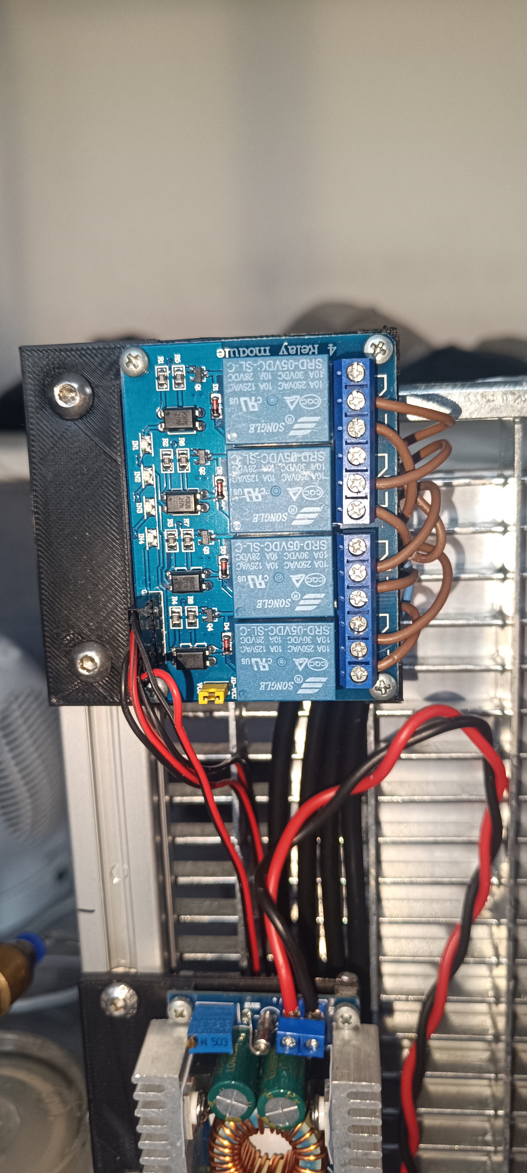
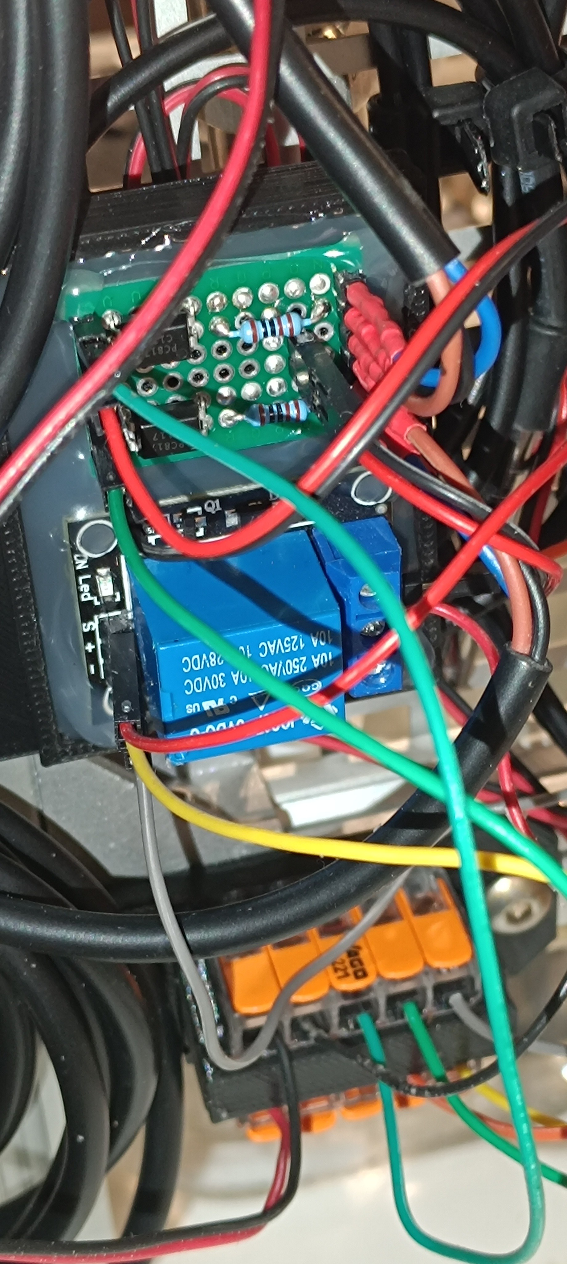
To deal with it, I'm currently using four of them connected in parallel to the ink line wired to a 4-channel relay module to run them one by one with a few seconds of overlapping to prevent the pressure from dropping while switching.
Four Solenoid Pumps connected in parallel4 Channel Relay Module
This way each pump is 1 minute turned on and 3 minutes turned off, which is 3 times the required off time for this model. While testing, they heated up, but not enough to be worried about melting the plastic around the coil.
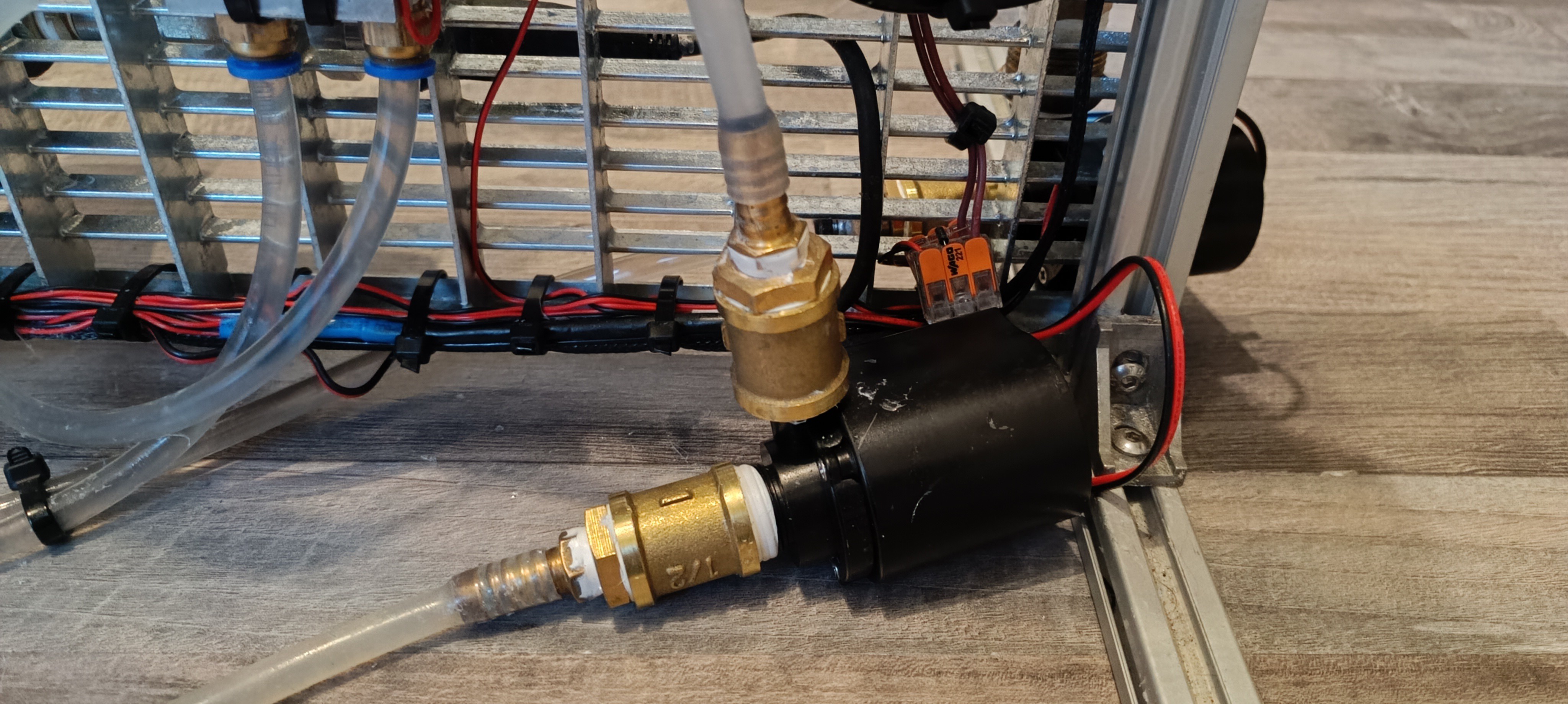
I'm currently using 4 of the ULKA NMEHP Type 1S models, which are small and silent pumps with a 1 min on / 1 min off rating.
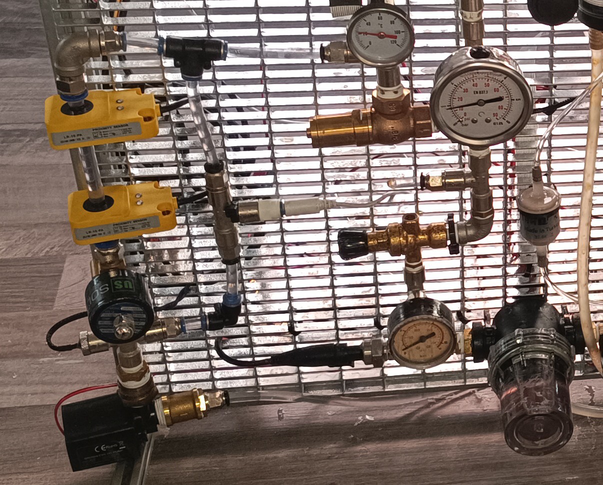
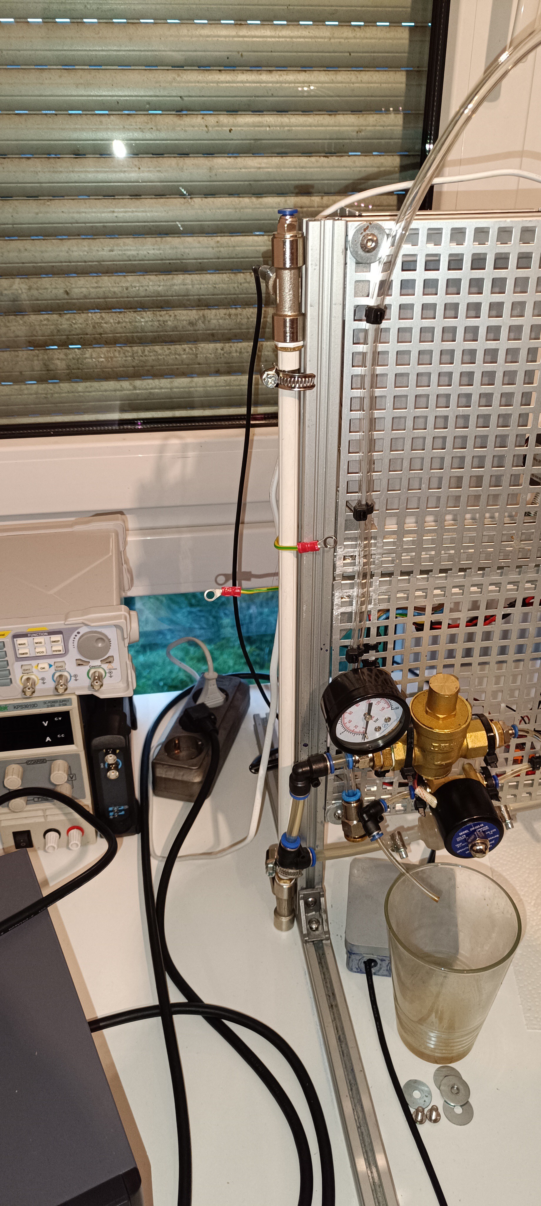
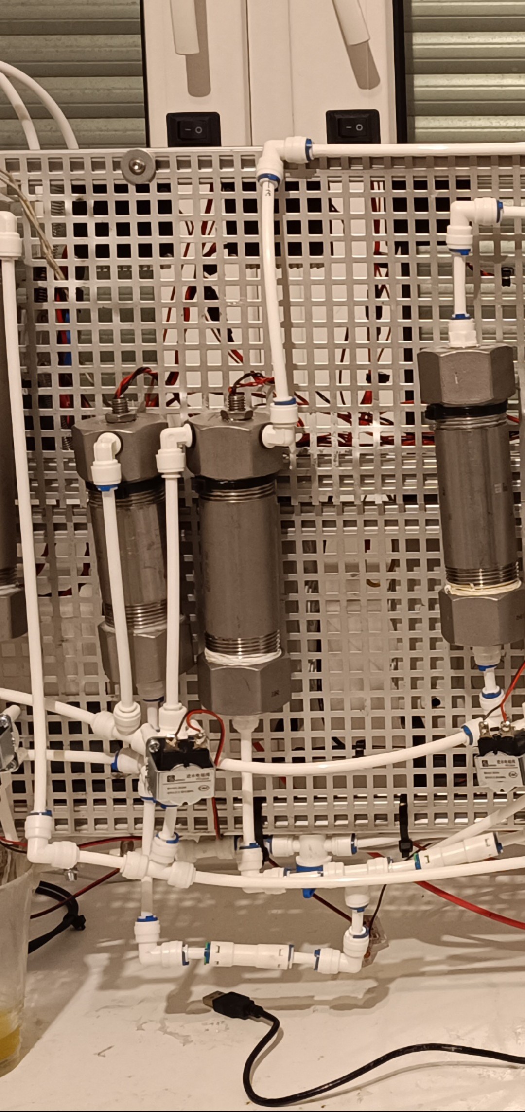
The ink is drawn from the tank into the pumps and is pumped into the high-pressure line. The system pressure is controlled by a relief valve which I set to around 50psi. The relief valve lets some of the ink flow back into the tank to keep the pressure steady.
The pressurized ink flows through a pressure regulator that regulates it down to the desired ink pressure of the stream (eg. 40psi). After that, it flows into a pressure accumulation tank/damper (just a tank with a hollow rubber ball inside) for stabilizing the pressure.
The idea behind that is, that by keeping the system pressure at 50 psi and by using a damper on the 40 psi side, pressure fluctuations on the 50 psi side will not affect the 40 psi side as long as the pressure doesn't drop below 40 psi at some point.
Now, when the ink valve is open, the ink flows to the printhead into the nozzle for ejecting the ink stream that hits the gutter to close the cycle.
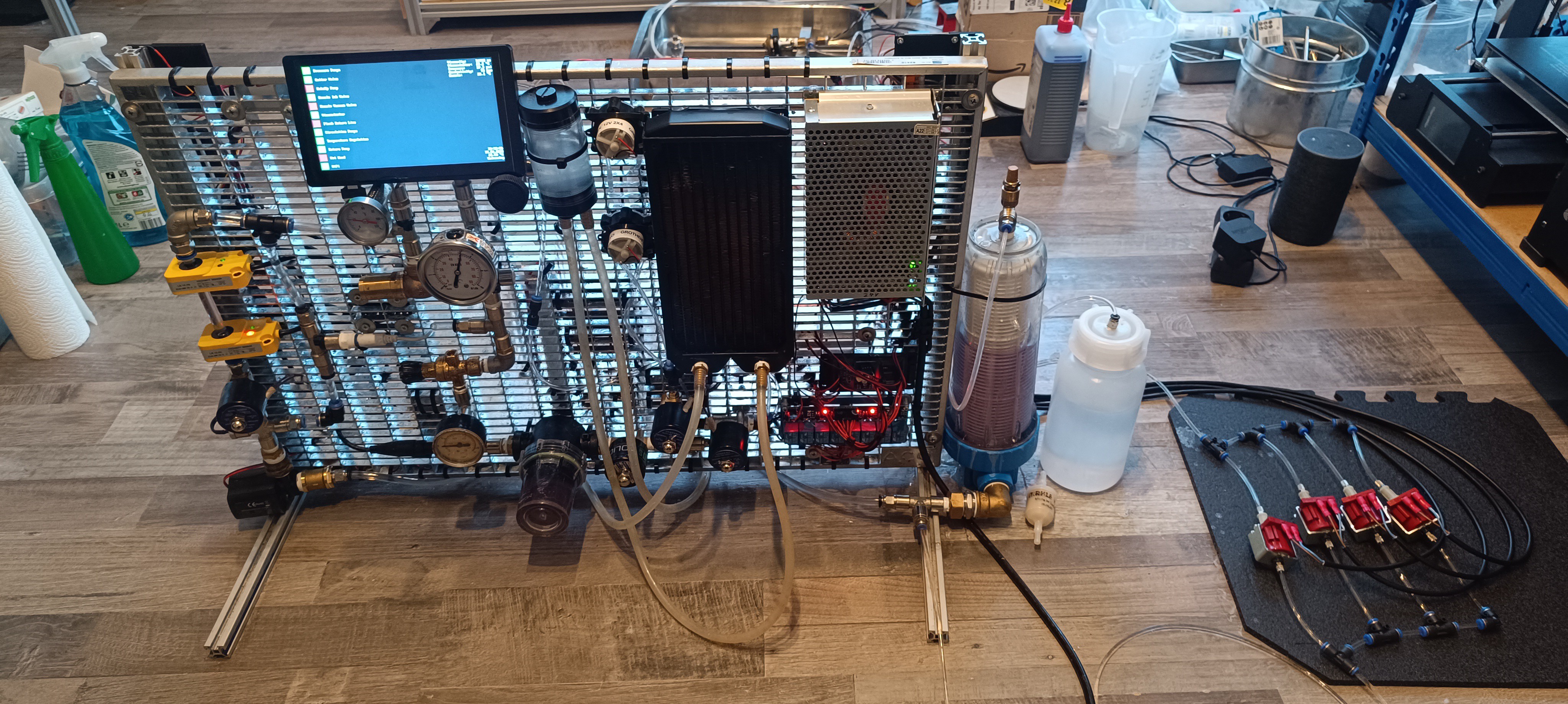
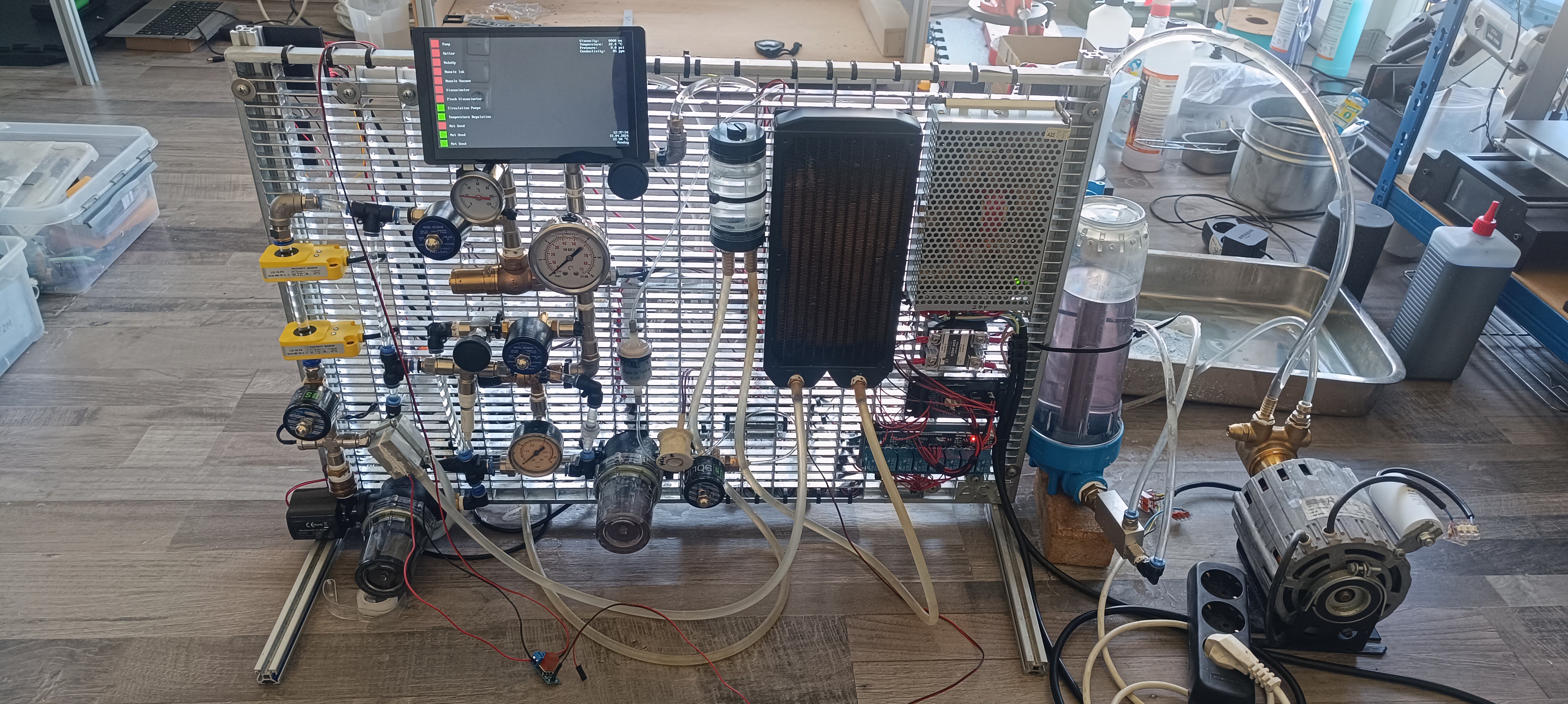
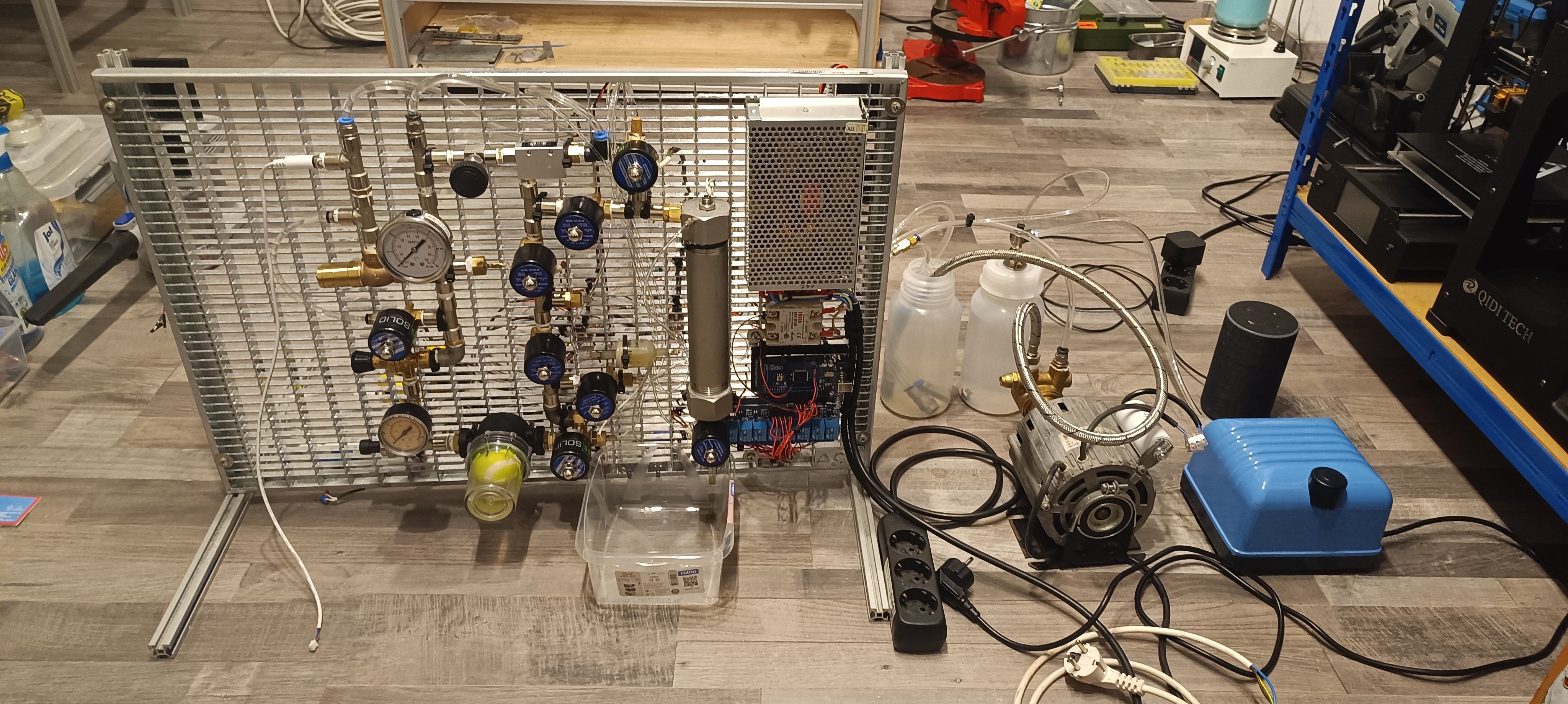
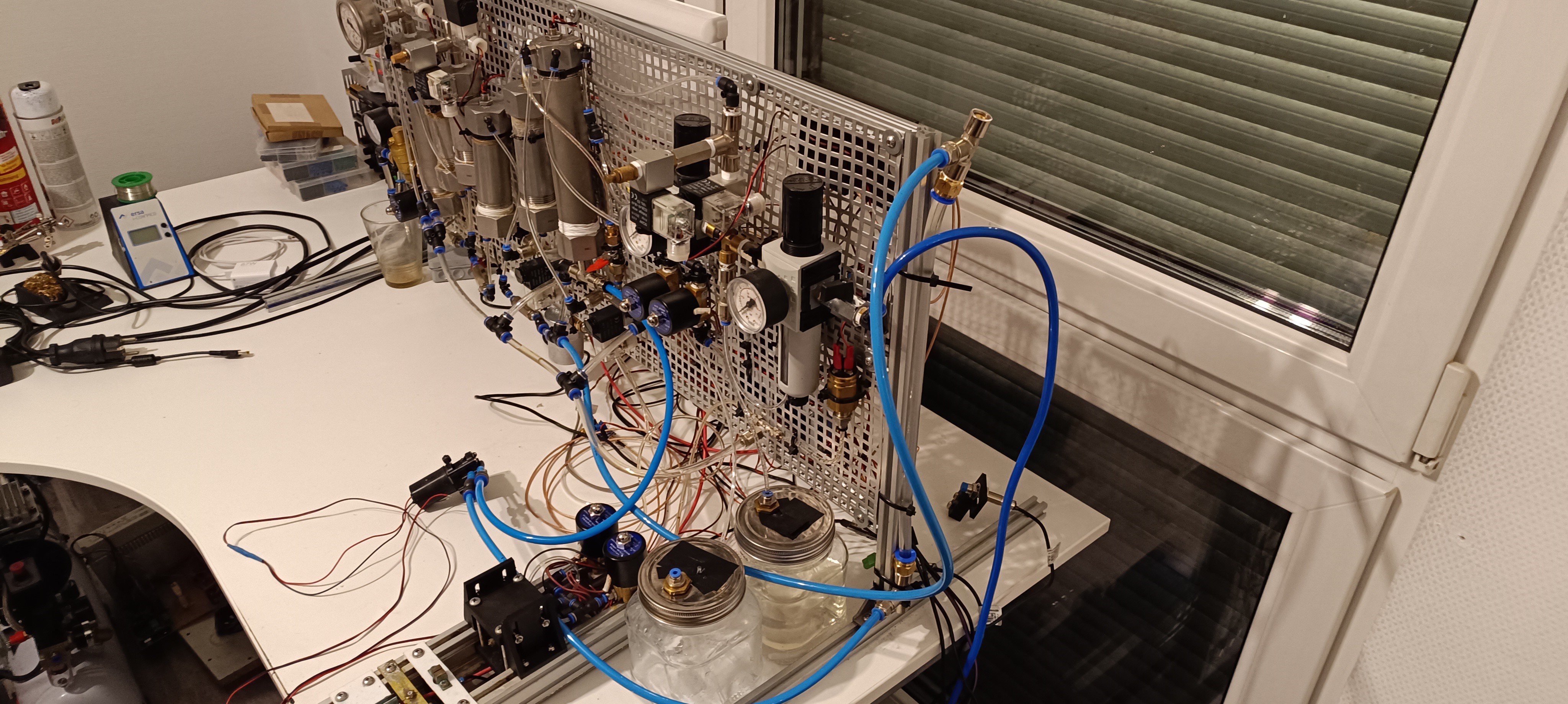
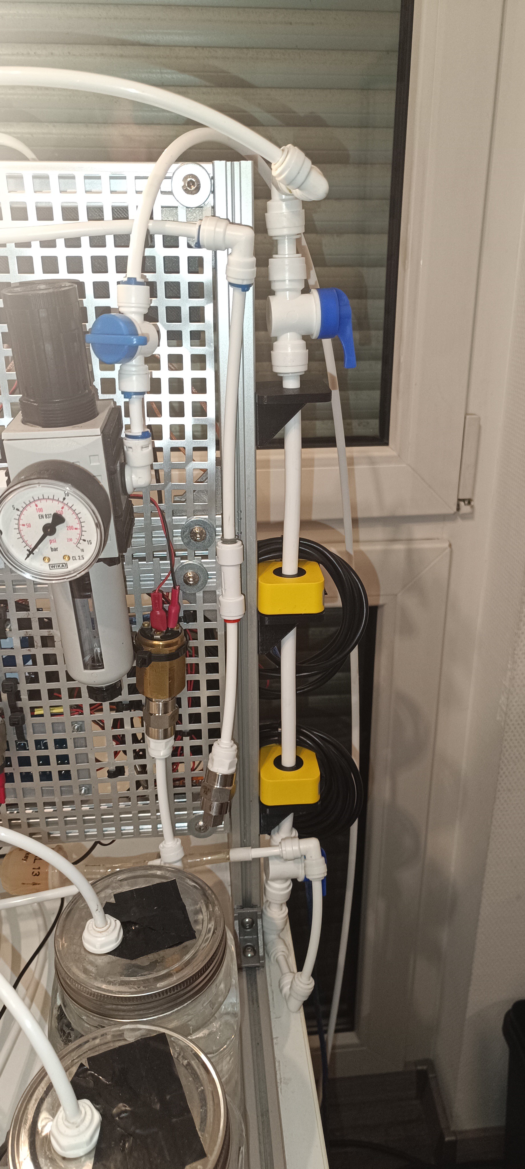
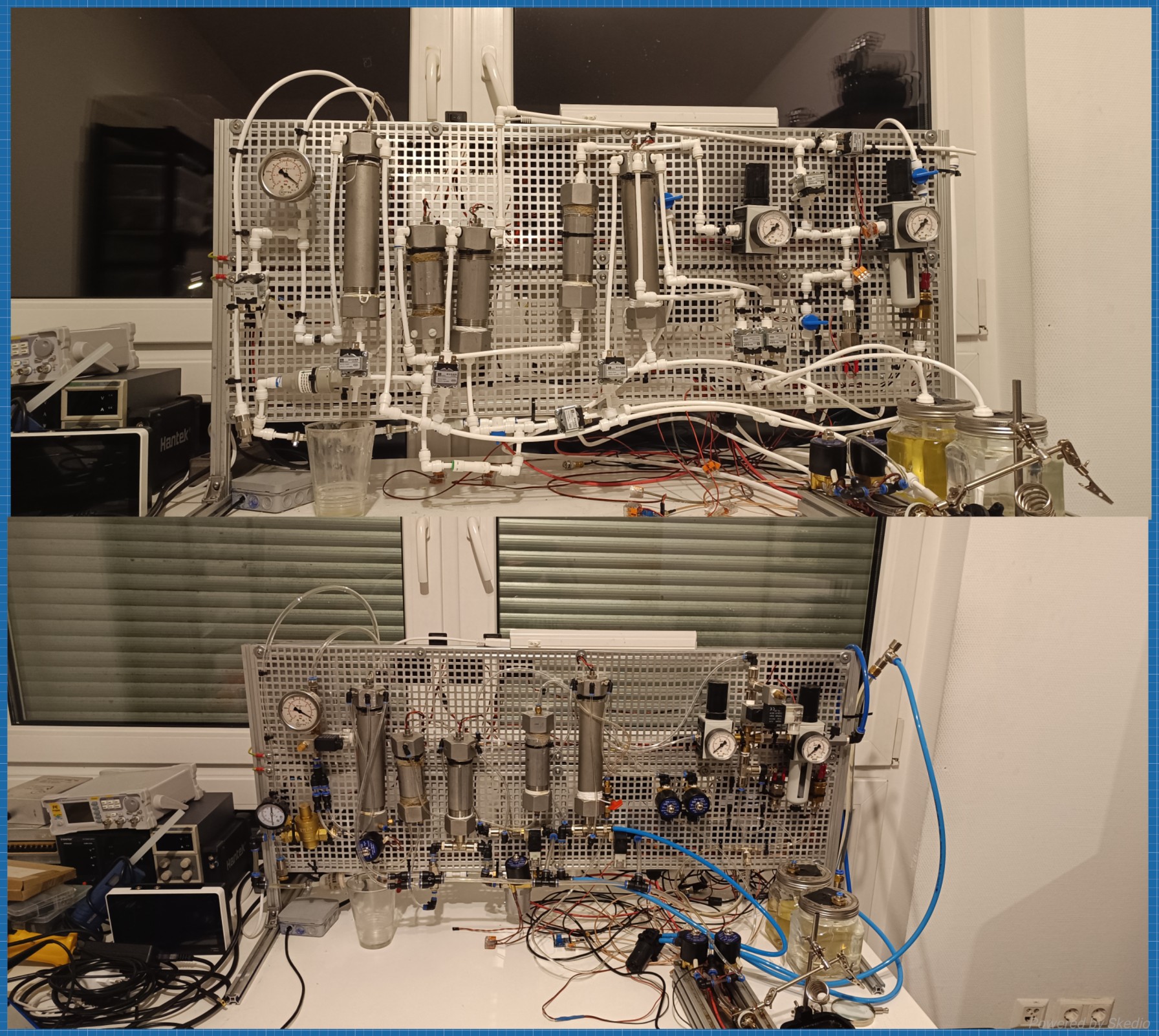
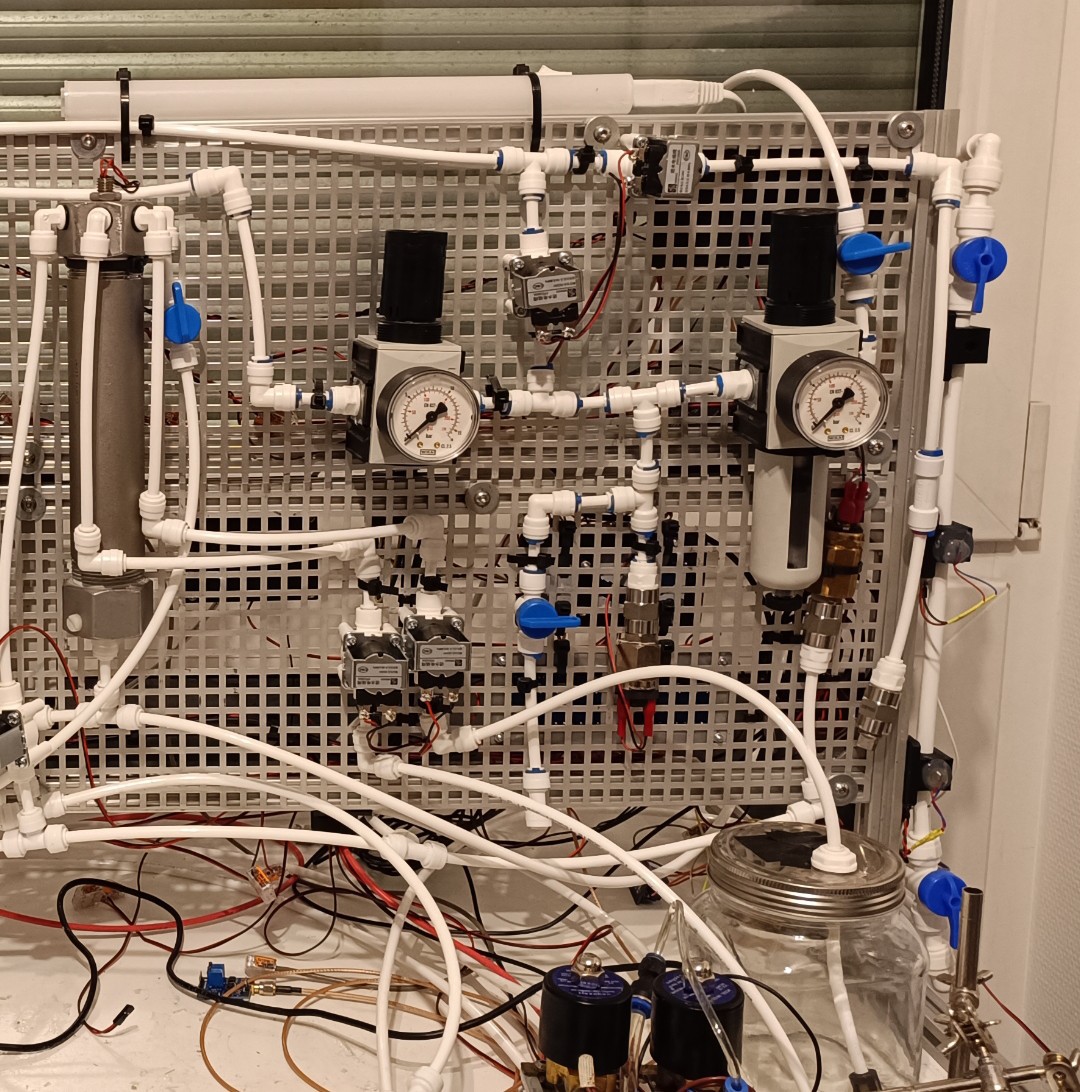
Back View of the Machine
Front View of the Machine
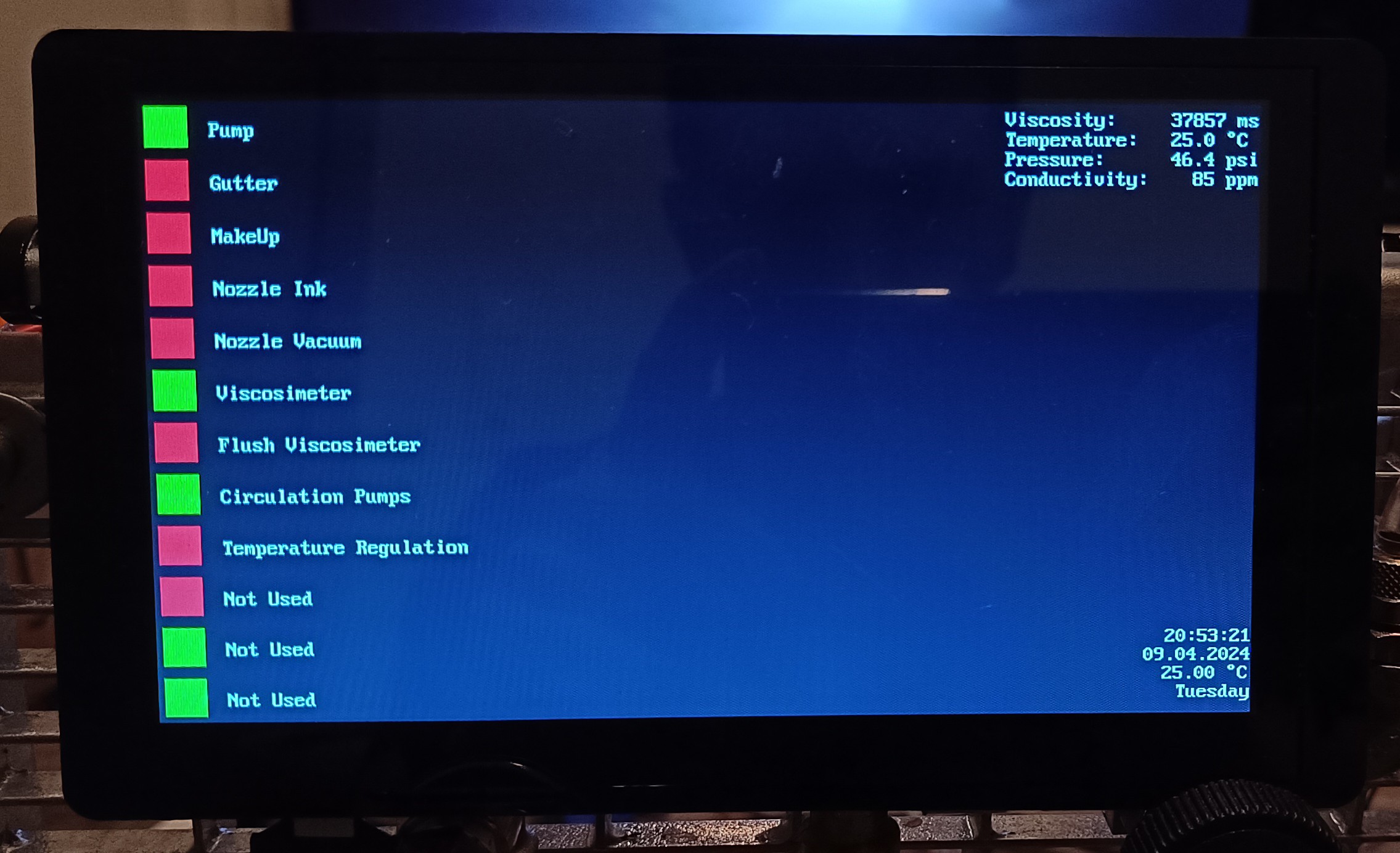
Touch UI
Summary
At first, I thought using many small pumps instead of one large pump would add more complexity to the project, but it turned out to be the opposite, here's why:
One large Pump
I searched for a long time until I found the portafilter coffee machine rotary vane pump that could supply high pressure at a high flow rate. I bought a used one for cheap, but when you buy these pumps new, they can easily cost multiple 100€. The pump I used was also quite noisy and introduced a lot of heat into the system.
I bought this pump especially to power the venturi nozzle which injected a lot of air bubbles into the ink, leading to a buildup of foam, damage on the pump vanes over time, and air bubbles mixed into the ink stream.
In short - I had a lot of problems with this pump.
Before I started using the small pumps I searched for other types of large pumps like garden pumps, hydraulic pumps, high-pressure fuel pumps, and diaphragm pumps, but none of them could meet all of the requirements.
There are also special CIJ pumps available, but they are very expensive and hard to get.
Since this is a DIY project I think it would be very frustrating for others to start the BOM with a pump that is expensive, loud, and hard to get, so I looked for alternative ways.
Multiple small Pumps
Brushless DC Pumps
I already started using the two brushless DC pumps for the new viscosimeter and later also used them for ink circulation. These pumps cost less than 30€ each and are relatively silent. There is also no special type required and it is possible to just use any pump that can provide enough flow and pressure to lift the steel ball inside the viscosimeter and circulate the ink.
Peristaltic Pumps
Same as for the brushless DC pumps, no special requirement, besides generating enough suction for drawing the ink and makeup to the tank. The pumps I used cost less than 30€ each, but any other peristaltic pump should work as well. They also are relatively silent.
Solenoid Pumps
The only requirement for these pumps is being able to supply the needed pressure (eg. 50 psi).
I used 4 small and silent ones which did not cost more than 20€ each, but if you can find a model that has a 100% duty cycle while providing enough pressure and having an acceptable noise level, you could also go with just one pump. The noise of the models I use is very low so it's sometimes hard to see if they are running without taking a look at the pressure gauge.
By replacing the large pumps with the small ones, the noise of the machine could be reduced so much that it is now more silent than my 3D printer. With that, running it at any time of the day including deep at night should no longer be a problem.
Conclusion
In my opinion, using different pump types for different tasks instead of just one pump type for everything makes a lot of things easier. It will be easier to find the right pumps for the project and if one pump should fail, you would just have to repair or replace this cheap (eg. 30€) pump instead of buying a new multi 100€ pump.
Thank you for your interest in my Projects
Great thanks to @Paulo Campos and Robert for helping me a lot with this project :)
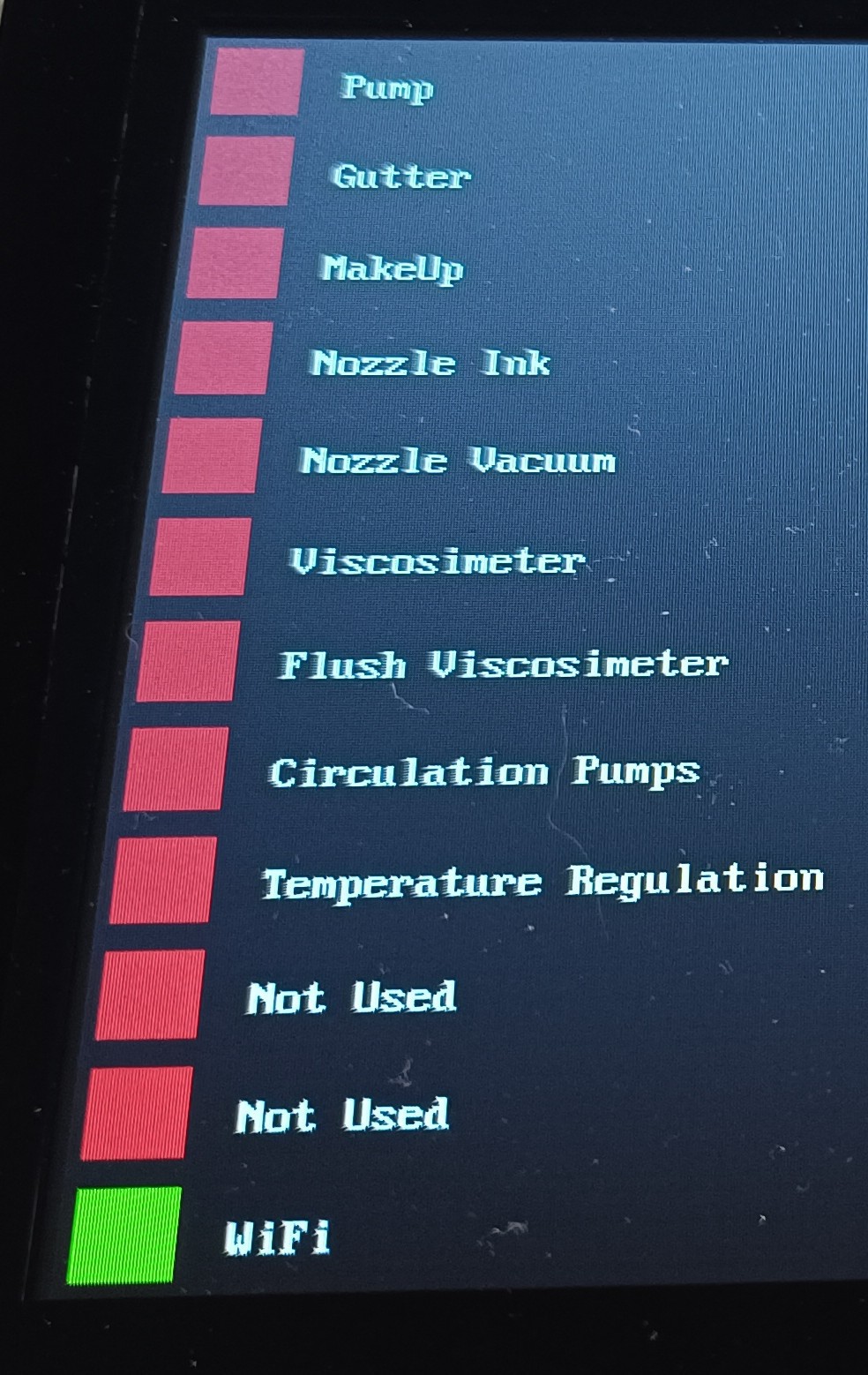
Here are some pictures of the 7-inch ESP32 powered control touchscreen and the latest changes to the prototype:
The squares on the left are touch buttons for the printer functions and on the right, you can see the sensor data on the top and the current time, date, day, and room temperature on the bottom.
ESP32 LCD Touchscreen
Since the display has no IO pins, I reassigned the 4 pins that were used for the micro SD card to use 2 of them for I2C (SCL and SDA) and the other two for PWM.
To access the pins I soldered wires to a micro SD extension flat-band cable.
Micro SD "Adapter"
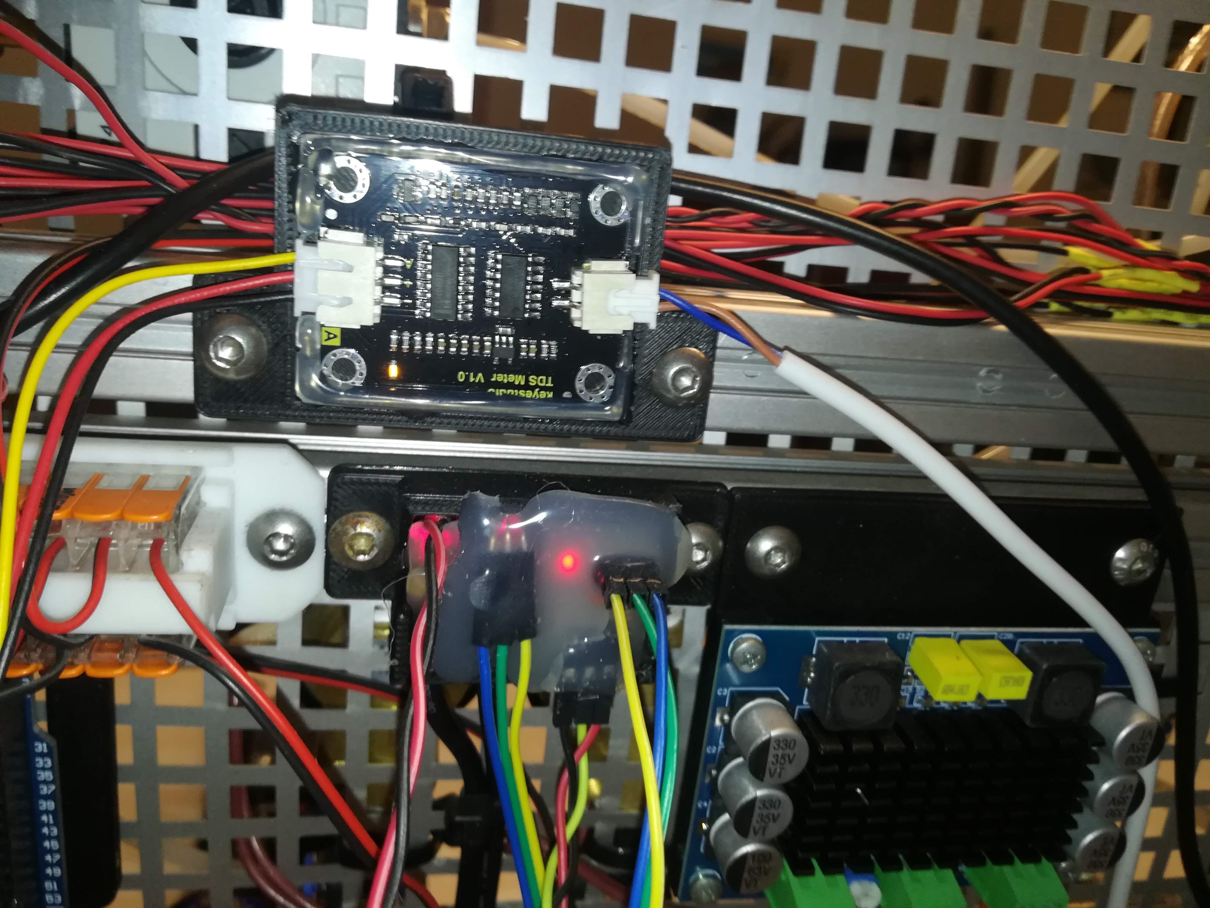
Connected via I2C are a DS3231 real-time clock, an ADS1115 ADC, and an MCP23017 IO extension.
ADS1115, DS3231, MCP23017 and 8Ch Relay Module
- The MCP23017 is used for switching the relays and valves and reading the inductive sensors of the viscosimeter.
- The ADS1115 is used for reading the analog voltage of the pressure, conductivity, and temperature sensors.
- The DS3231 is used to keep track of the time and measure the room temperature.
3.3V/5V logic level converter and AMS1117
The touchscreen is powered by an AMS1117 3.3V regulator.
While the ESP32 is running well on 3.3V the LCD seems to need a higher voltage since it's flickering a bit when powered by 3.3V which doesn't happen when powered by its USB-C connection.
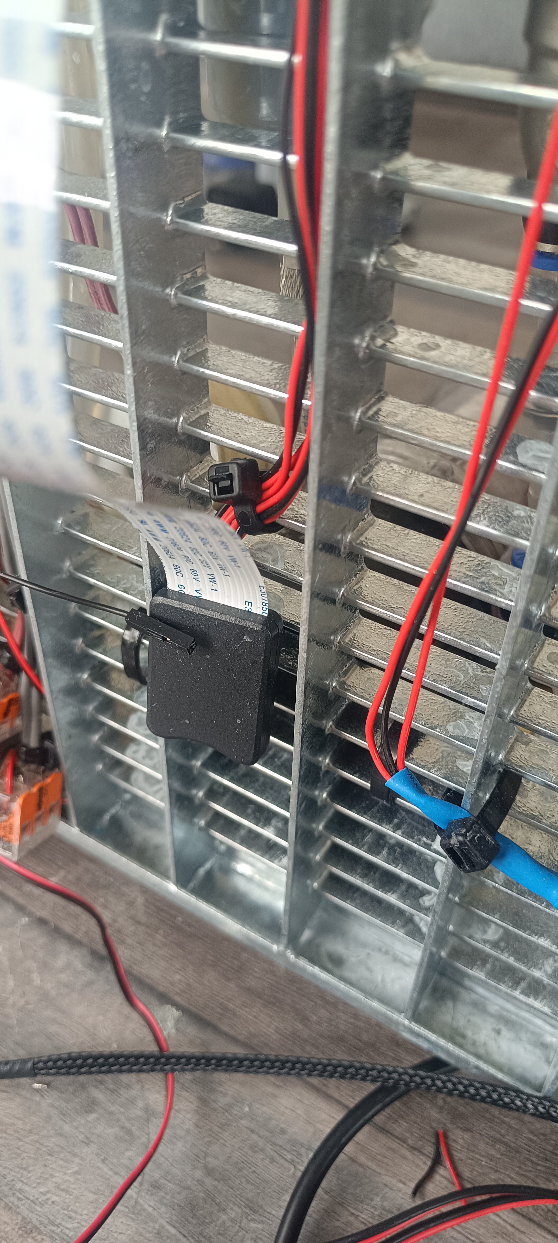
To get rid of the heat from the Peltier module I added a dual-fan radiator, with the fans pointing toward the grid frame of the machine.
Backside of the RadiatorFront View of the Machine
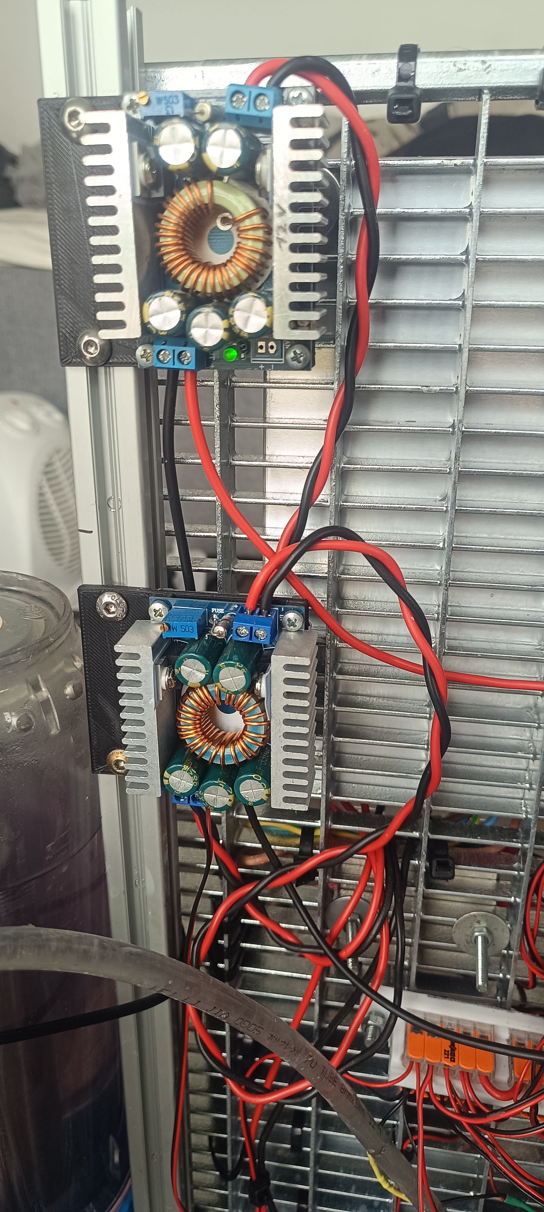
Currently, I'm using two XL4016 step-down converters for converting 24V from the power supply to 5V and 12V.
While the 5V is used for powering the I2C devices and sensors, the 12V is used for the Peltier module and viscosimeter valve.
XL4016 for 12V and 5V
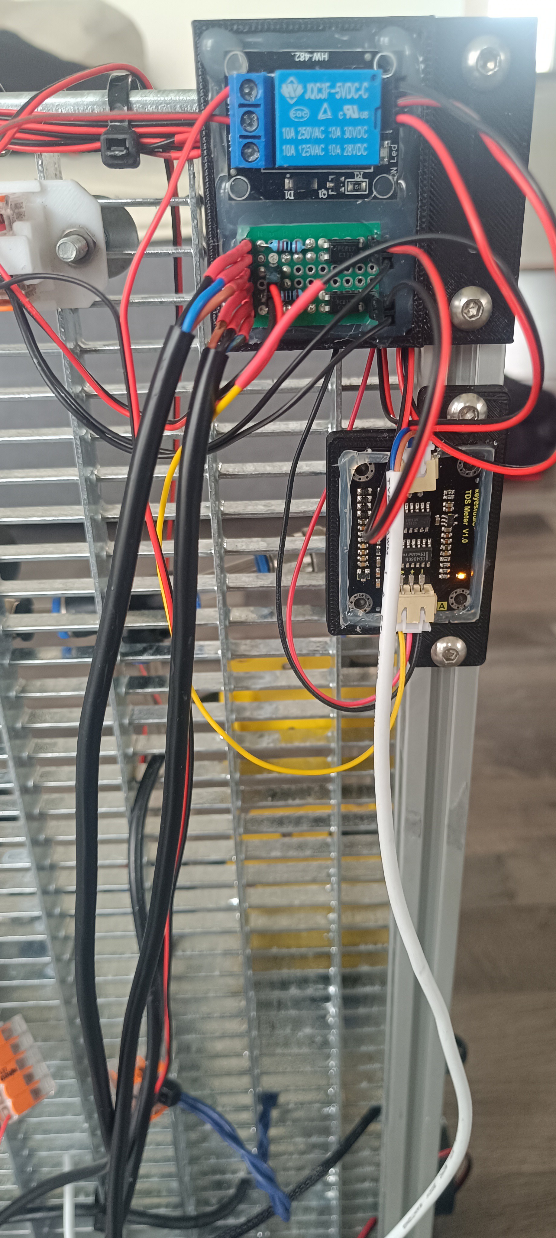
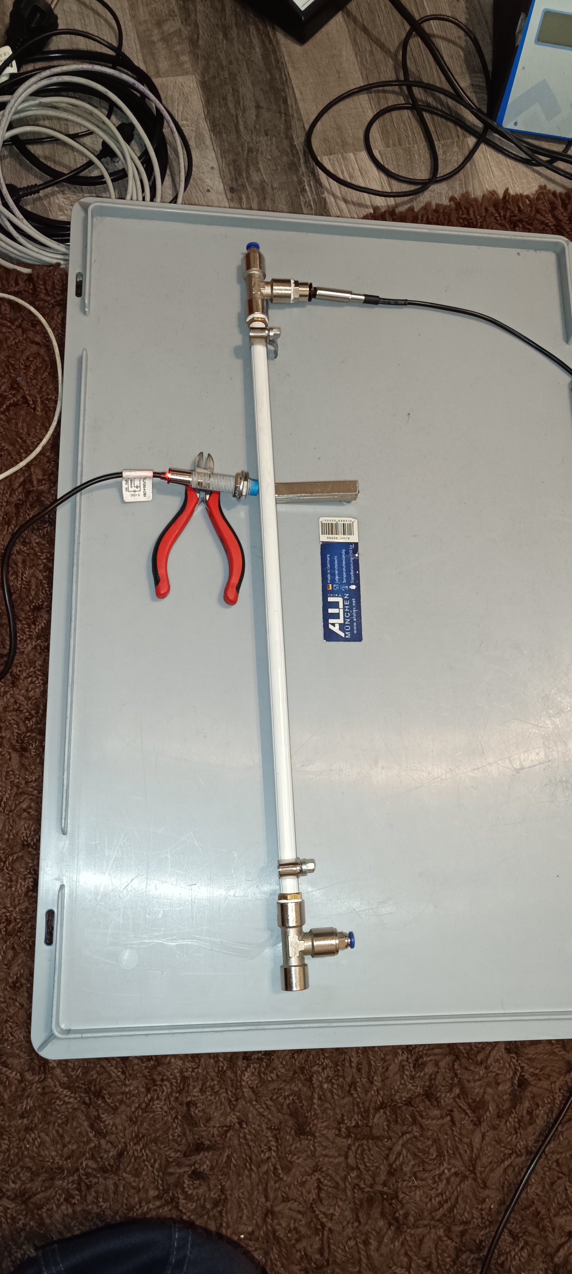
A single relay module is used to open the valve for lifting the 8mm steel ball inside the viscosimeter. The falling steel ball gets detected by 2 inductive sensors.
For the viscosimeter, I used a clear polycarbonate pipe with a 10x8mm diameter and 150mm length. The distance between the two sensors is 60mm.
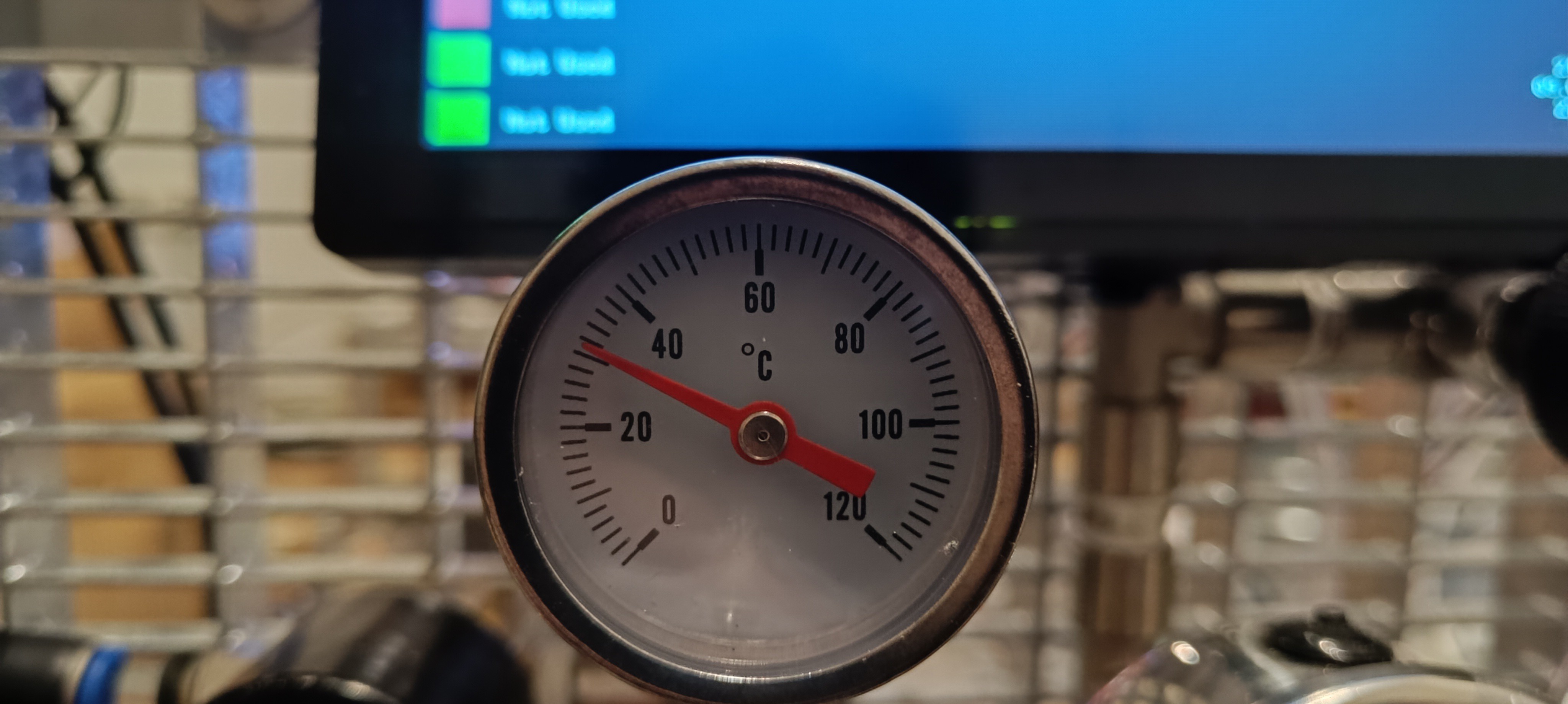
New Viscosimeter with Peltier Module and Circulation PumpThermometer on the Main Ink Cycle
I used a dual MOSFET module for switching the 12706 Peltier module with a 1kHz PWM signal.
Dual MOSFET Module
The Peltier model draws around 50W during testing and the MOSFET module gets very hot without cooling so I will likely place the MOSFET modules for both Peltier modules next to each other and add a small silent 40mm fan for cooling.
Peltier Module
Together with the pump that pumps the ink around inside the viscosimeter and also heats it up, a thermistor in the cross-fitting, and some PID code, the temperature of the ink inside the viscosimeter can be kept constant without oscillation.
In the future, I will add some code to flush the viscosimeter from time to time with fresh ink to check if the viscosity has changed and automatically add solvent if the viscosity has risen too high because of solvent evaporation.
For flushing, the viscosimeter is connected to the main ink cycle by two valves that can be opened to let fresh ink flow through the viscosimeter while the pump is running and the measuring pipe's valve is opened to flush all the old ink out.
LCD with Wifi Connection IndicatorFor the next update I'm planning to add a data logging feature to write all sensor readings and machine function states together with a timestamp to a file on an FTP server to make it possible to analyze every test run and see what changes in the sensor readings follow the performed action.
I think this will add a lot of value to the machine since it makes the testing results more comparable and will provide a way to share the collected data besides recording videos and taking pictures. In the best case, it would be possible to display the sensor readings as graph lines and have a way to see which machine function was active at a time, e.g. to see that the viscosity decreases with a temperature rise or that the pressure drops when the ink valve is opened and so on.
I'm still working on the project and over the last months I added an ESP32 powered 7-inch touch panel to the machine and changed the code so that a PC is no longer needed for running the machine.
I also built a new viscosimeter that features a thermistor, Peltier cooler, and circulation pump for keeping the temperature, always the same while measuring, even if the room temperature changes.
Before, I couldn't get a reliable reading of the ink's viscosity since it changed from day to day depending on the room temperature. On some days when the sun was heating the room all day long the ball drop time reduced by it's half just by the rising of the temperature during the day.
When the ink gets pumped around it also heats up, so that without cooling the viscosity would continuously drop until the temperature reaches its highest point which is also dependent on the room temperature.
The good thing about ink heating is, that with it the ink in the viscosimeter and the rest of the printer heats up on its own so that only cooling is necessary to keep the ink temperature stable.
Currently, I only finished the Peltier cooler of the viscosimeter, but I will also add a cooler to the printhead to keep the ink that exits the nozzle at the same temperature as the ink sample in the viscosimeter so that the measured viscosity equals the viscosity of the ink stream.
While I haven't seen a cooling system on any CIJ printer so far, I have seen designs that feature a temperature sensor on the viscosimeter and on the nozzle.
In contrast to commercial manufacturers who put a lot of work into designing the best ink for their products, I don't know the temperature-viscosity curve of the ink mixtures I'm using and I think it is nice to have a way to keep the ink's temperature constant at the nozzle and the viscosimeter.
The current printer is powered by pressurized air from an air compressor and vacuum from a vacuum pump. Both the pressurized air and vacuum are used to move the ink around.
Pneumatic-Powered Printer
The pressurized air pushes the ink from the ink tank to the printhead and through the nozzle forming the ink stream that hits the opening of the gutter. From there the ink gets drawn into the reservoir tank by vacuum. It gets collected there until the ink tank needs to be refilled. Then the ink gets drawn from the reservoir tank into the pump tank by vacuum. When the pump tank is filled, pressurized air with a higher pressure than that of the ink tank is applied to the pump tank to pump the ink from the pump tank into the ink tank.
Compared to that, the new hydraulic-powered printer is much simpler since it uses ink as a hydraulic fluid. This way the pressurized ink can be taken from the hydraulic system which can also generate the vacuum that is needed for drawing the ink back into the system by the use of a hydraulic-powered venturi pump.
Because of that, there is no need for a separate vacuum pump or air compressor which will make the printer cheaper, less complex, and more compact.
All it needs is a powerful ink pump and a low-pressure air pump to power the hydraulic-powered printer.
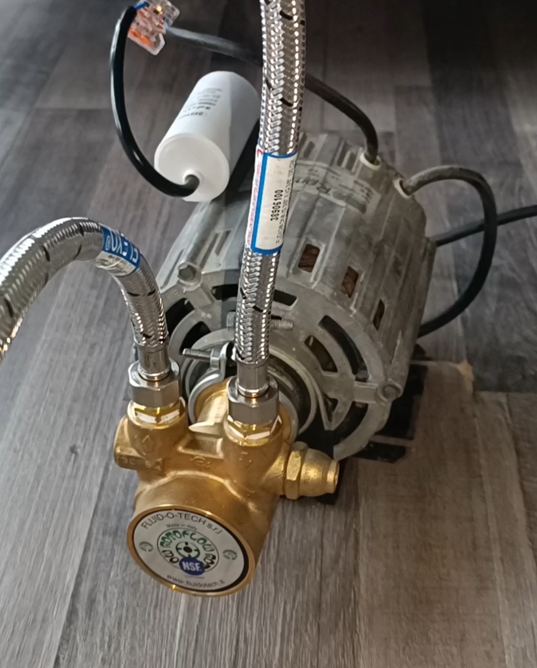
For that, I used a Fluid-O-Tech rotating vane pump (200l/h) and an AquaForte v30 pond air pump.
Hydraulic-Powered Printer
Until lately, I didn't know anything about hydraulic systems and so I thought the pump's output would have to go directly to the nozzle, which would have made finding a suitable pump very hard, but just a few weeks ago I read an article about RC hydraulic systems where they used a relief valve for limiting the hydraulic pressure by feeding some of the pump's output back to the tank.
This makes everything easier because, by the use of such a relief valve, a pump running at a constant speed and a much higher flow rate than that what is used by the ink stream can be used for powering the system.
The same can also be done by the use of fixed restrictions and a PWM-controlled pump, but since the constant flow pump + relief valve were cheaper, I used this method.
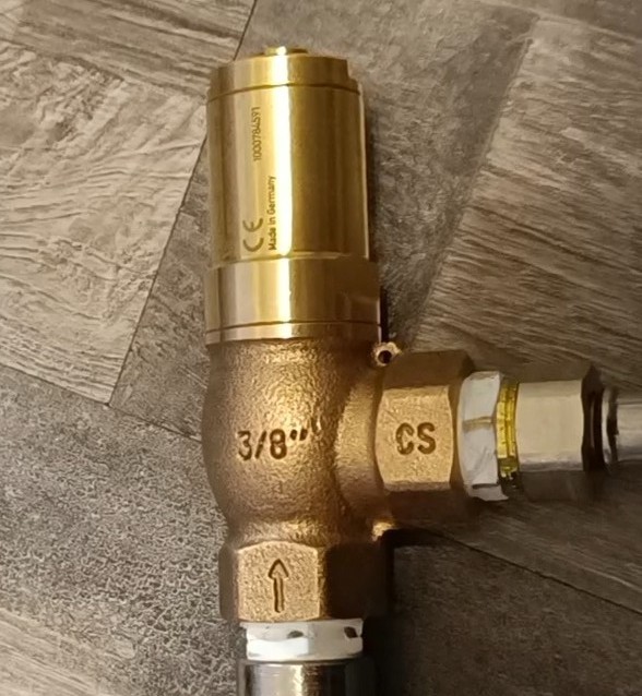
After reading about the relief valve I looked for such a valve, but since hydraulic system relief valves are usually designed to work at high pressures e.g. from 10 to 200 bar I had to look for a relief valve that is designed to work at low pressures and so I bought a water relief valve that is designed to work from 2 to 8 bar.
Relief Valve
The valve I got works by opening up just enough to keep the pressure before the valve at the set level. When now some valve opens up to supply e.g. the venturi pump, printhead, or viscosimeter with ink, the relief valve restricts the flow out of it to keep the pressure of the system at the set level. It has a "screw" at the top that compresses a spring for setting the pressure.
The valve was the first element of the new printer design and after confirming that it worked the way I thought it would, I ordered a venturi pump for testing both together to see if I could get the set system pressure and the needed vacuum for the printer from those two parts.
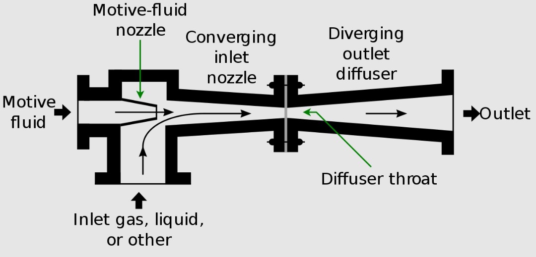
Venturi pumpInner Structure of the Venturi Pump
The venturi pump can generate a vacuum by the use of a gas or fluid that "draws" the air with it when it is ejected from a small nozzle into a narrowing and then expanding tube.
I was a bit worried if it would work at all since the type of venturi pump I used is intended to be used with pressurized air, but it turned out to work pretty well with water when I tested it out.
With that, I could confirm that just a supply of fluid at the right pressure and flow rate can be used to power the printer.
A few Parts of the Printer
After testing out the relief valve and venturi pump, next up was finding the right ink pump.
This was not that easy, because the pump has to provide some capabilities to be suitable for the task:
- It has to provide at least 40 psi of pressure.
- It has to provide a flow high enough to power the venturi pump, printhead, and viscosimeter.
- It needs to be able to run continuously for a long time.
- It needs to be able to handle solvents and flammable liquids like ethanol-based ink.
First, I thought about using a multi-chamber diaphragm pump, because these pumps are not that noisy and can provide the needed pressure, but since all pumps, I could find claim to be not suitable for flammable liquids, they were not an option.
Later, I found out that there are specialized diaphragm pumps for lab and industry use that can handle flammable and corrosive liquids, but they are also very expensive.
After more searching, I ordered two hydraulic pumps, one RC hydraulic pump driven by a BLDC motor and another hydraulic pump without a motor.
RC Hydraulic Pump with BLDC Motor
After getting everything ready for running the pump I connected the pump to the relief valve, set the pressure to 40 psi, and let it run for a while.
At first, it looked very promising, but it didn't take long until it became visible that the gears were wearing down rapidly.
The water got darker from metal particles, the pump started stalling from time to time until it finally failed.
So, it seems like this pump can only be used with hydraulic oil and not with water or ethanol.
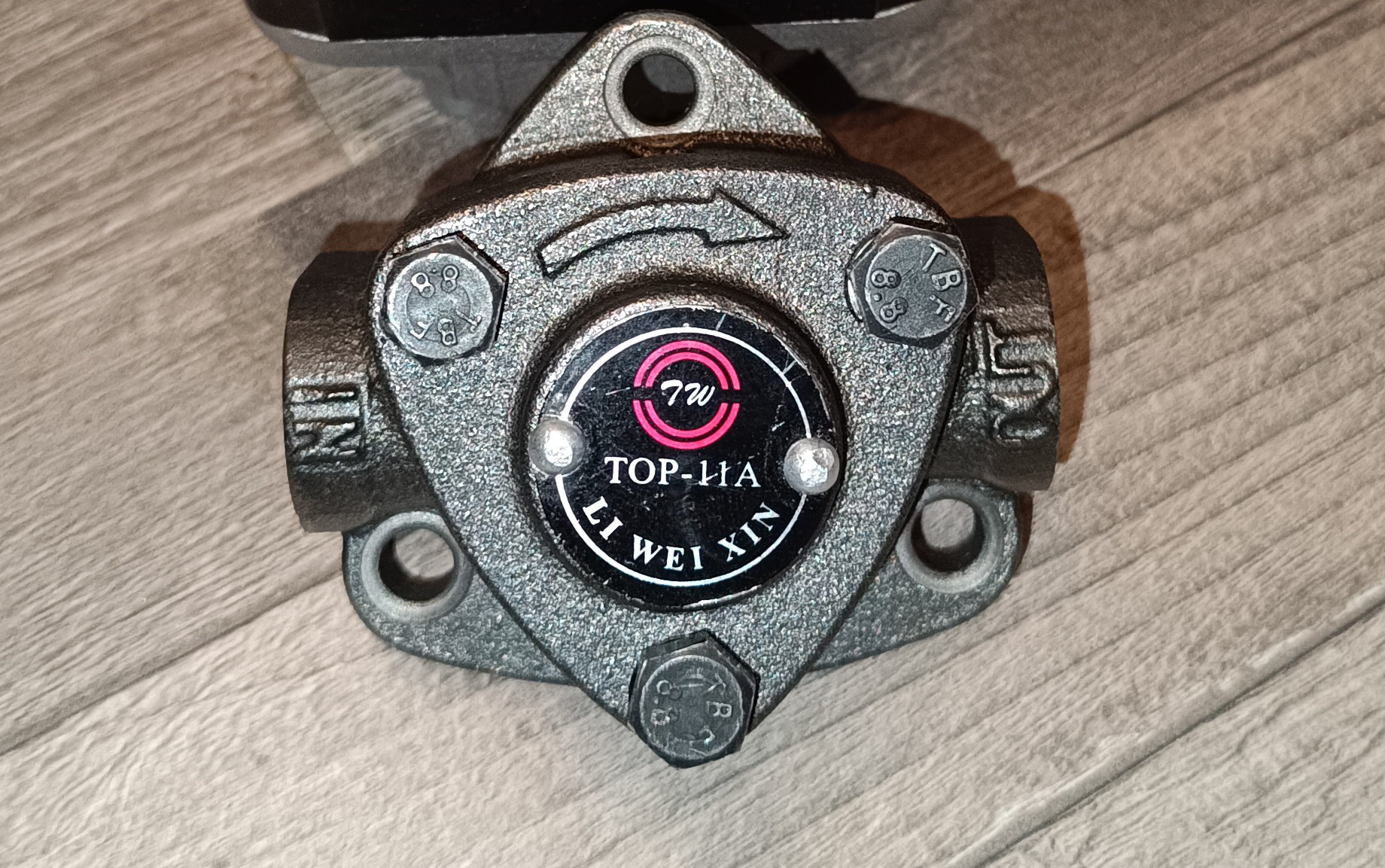
Top 11A Pump
For testing out the second hydraulic pump I connected it to the relief valve, set the pressure to 40 psi, and connected it to a small AC motor with a GT2 belt. Shortly after, I realized that this pump stalls as soon as there is force applied to the side of the shaft (by the belt in this case).
So, I tried driving it with the AC motor directly, which unfortunately was not able to drive the pump.
Because of that I tried driving the pump with a small DC motor, which could drive the pump, but was also a bit weak so that the speed at the point of highest resistance in the rotation was a bit lower so that the pressure was varying a lot.
Later, I found out that the motor that is usually used for driving this kind of pump is much more powerful than the motors I used for testing.
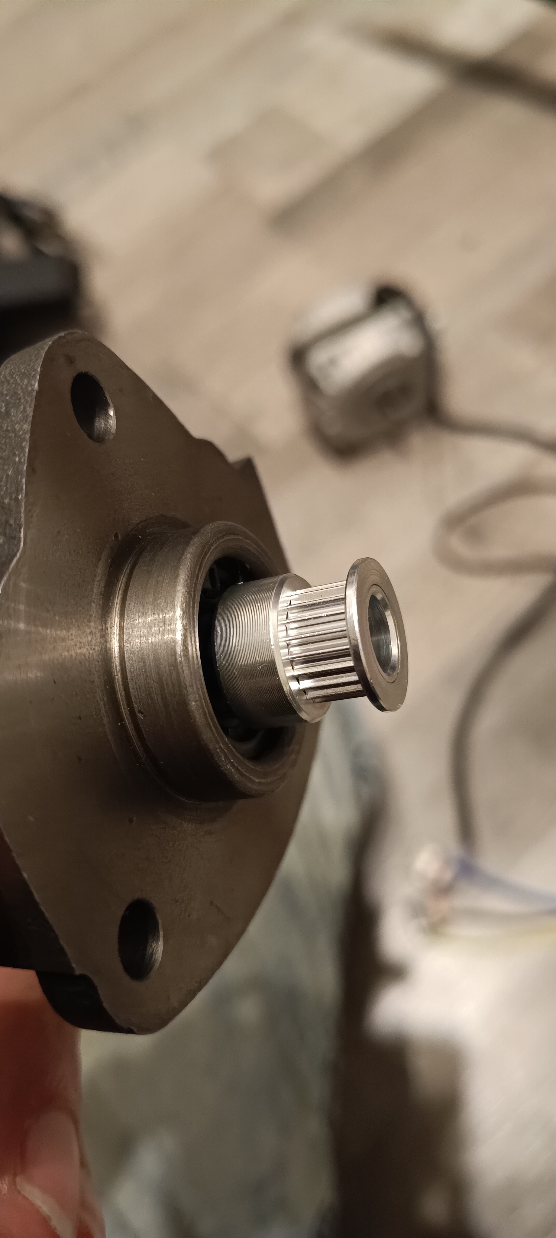
Shaft of the Pump with a GT2 Pulley
What I learned from this test and the search for the pump is that pumps like these are sold in two ways, separately and also together with the right motor. I think this is done so you don't have to buy both the pump and the motor if only the pump needs to be replaced.
While testing out the last hydraulic pump, I was worried about corrosion, since the one I got seemed to be made out of cast iron, and while the ink with the sodium acetate is no longer that corrosive against brass, aluminum, and copper, it still is corrosive against iron which even starts rusting when it comes in contact with tap water.
Because of that, I searched for other pumps and saw that there are rotating vane pumps available made out of either stainless steel or brass which can provide the needed pressure, flow, and chemical resistance while at the same time being able to run continuously and being able to handle flammable liquids like gasoline and ethanol.
Rotating Vane Pump
The problem at this point was that I did not know where to get the motor for these since I found the pump by accident and never saw the pump + motor assembled.
So, I spent some more time searching until I finally found the same pump type used in portafilter coffee machines.
With this in mind, I searched for a used portafilter coffee machine pump and ordered a cheap one.
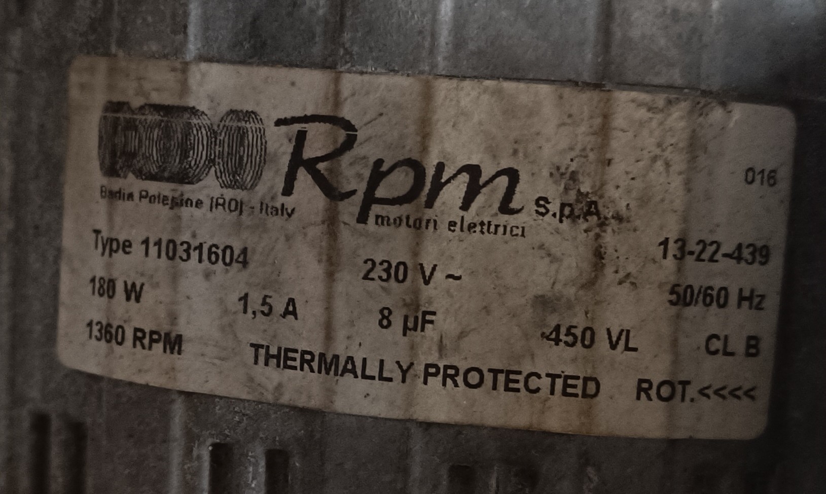
After a few days, the pump arrived, but something was wrong... the motor got delivered without its capacitor.
The Motor's Label
So, I ordered a new capacitor and started the motor, but there was still something wrong...
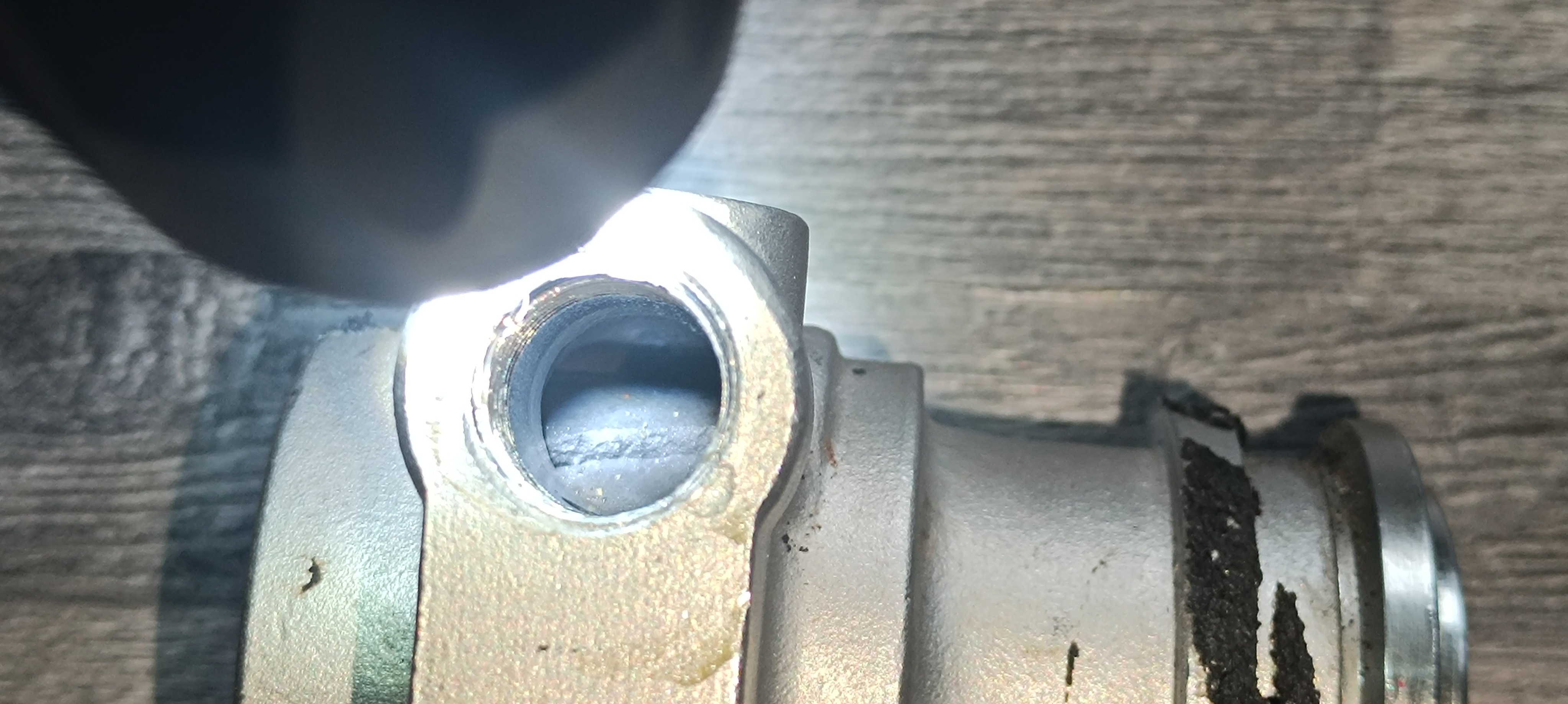
the pump connected to the motor was broken.
Something was broken inside the Pump
Now the knowledge about the offer for the pump I saw before came in handy. I compared the dimensions of the pumps' "mounting rings" and they seemed to be identical.
So, I ordered the pump I saw before.
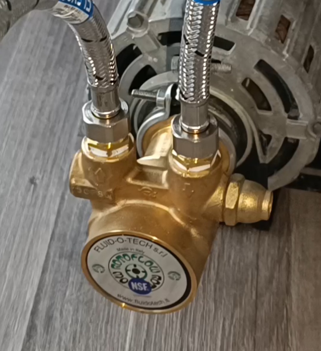
Motor with new Pump
When I then mounted the new pump and started the motor it finally worked.
The pump is now able to run continuously without overheating and can deliver the needed flow and pressure. Together with the relief valve and venturi pump it can supply all that's needed for running the printer, so I could finally start building the new hydraulic-powered printer.
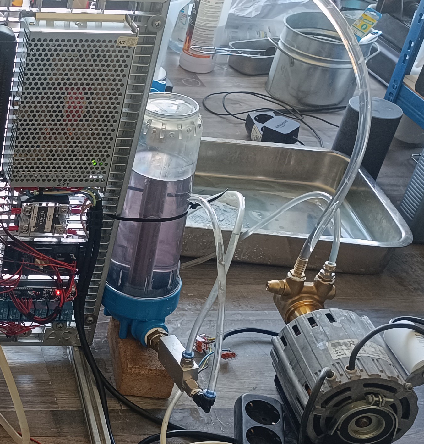
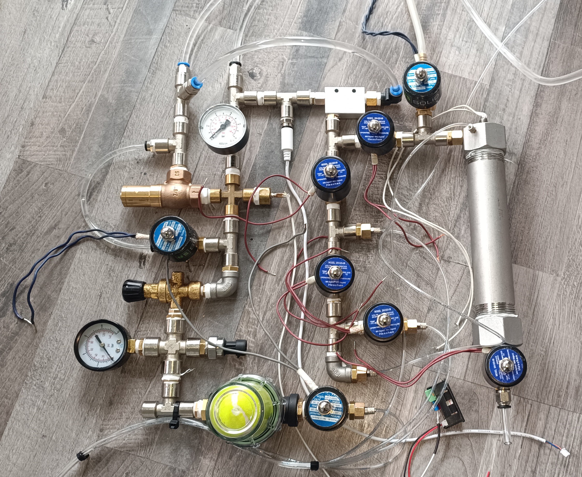
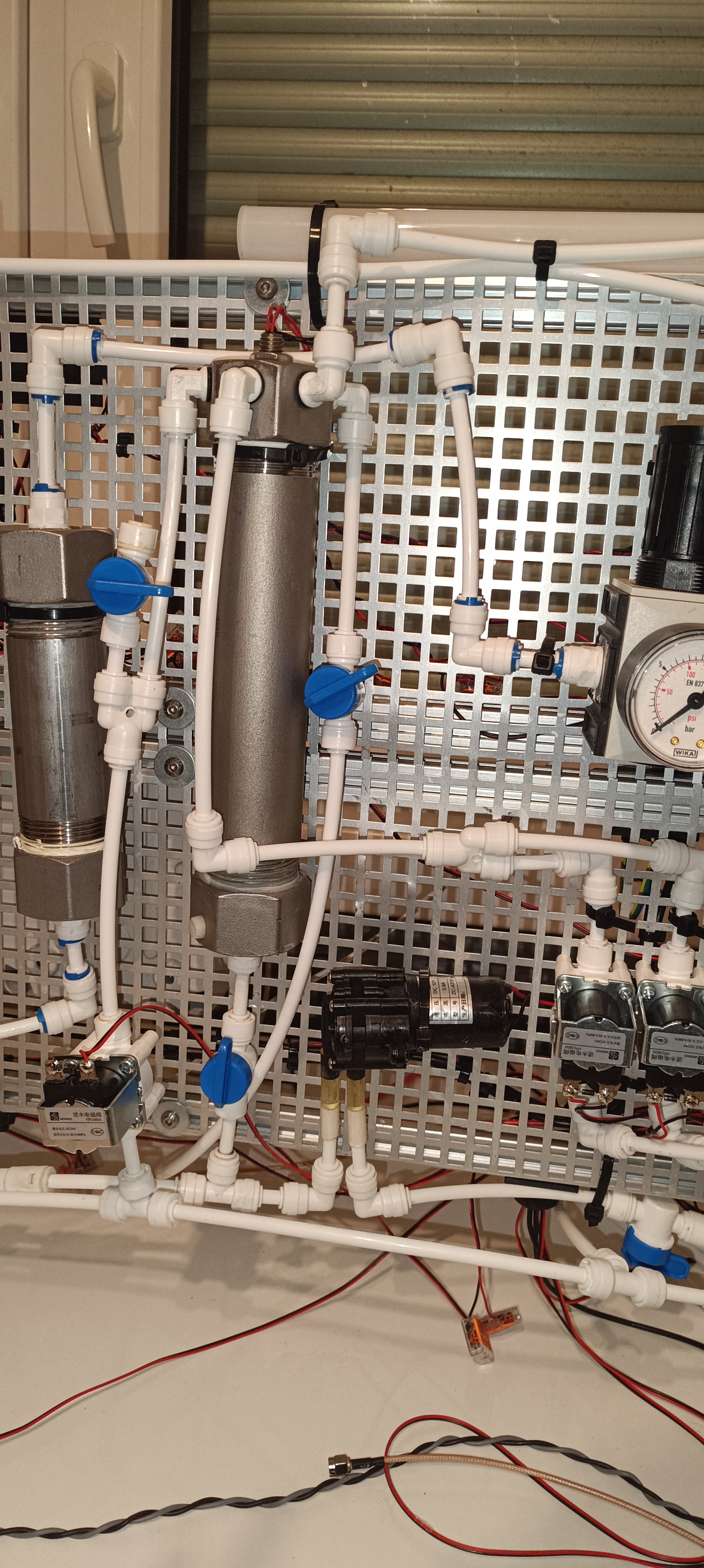
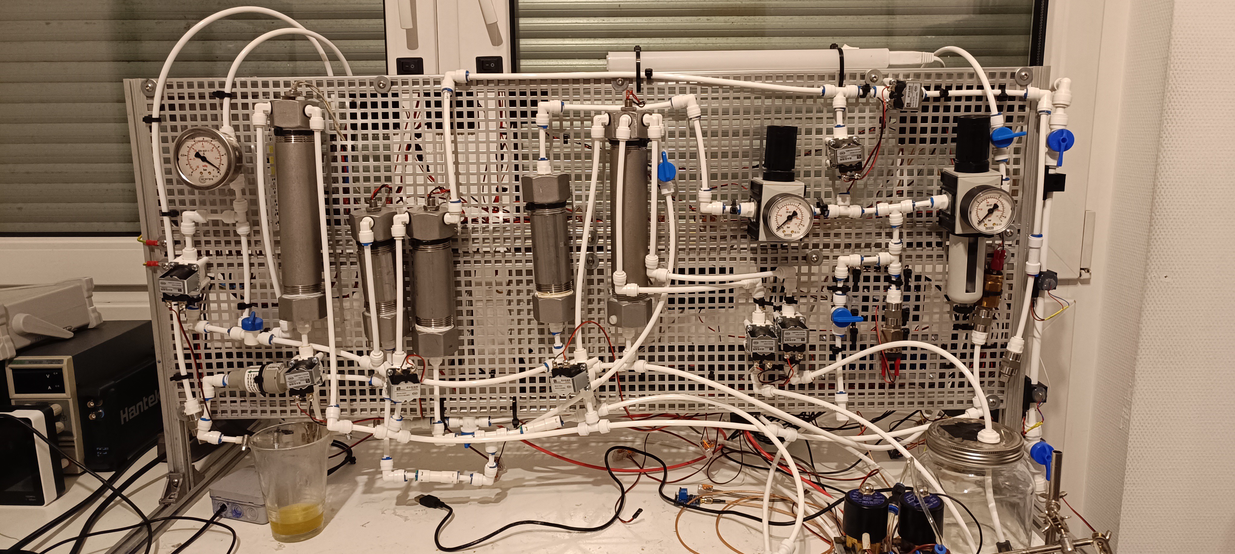
Working on the new PrinterAll Parts Together
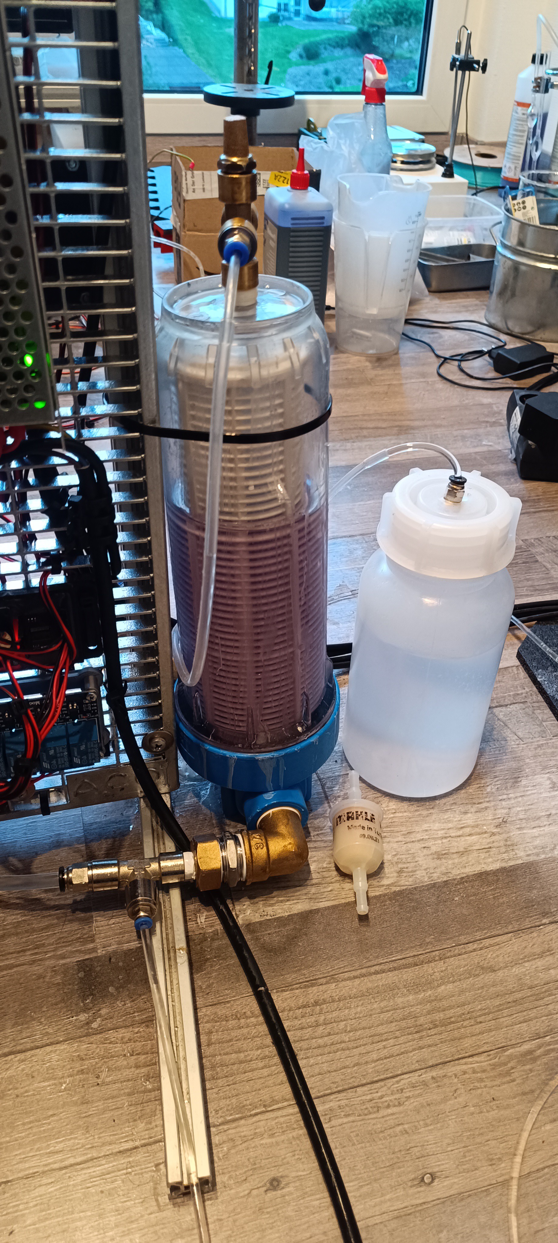
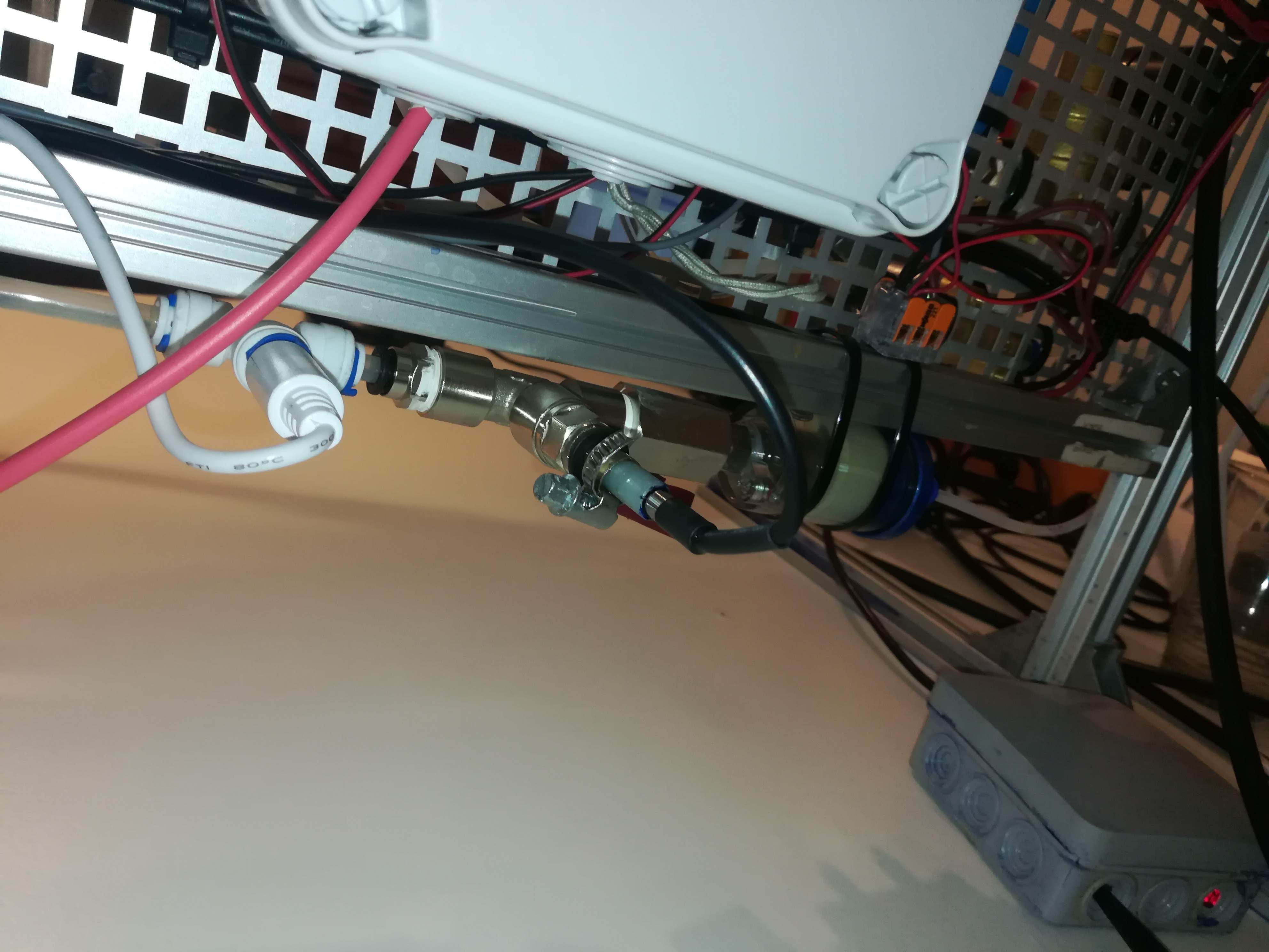
One note on the green thing at the bottom of the plumbing, the gauge, and the pressure regulator before it:
Since there are parts of the printer that apply varying loads on the system like the viscosimeter and especially the venturi pump, the pressure in the system is not perfectly stable. Because of that I used a higher pressure for the system pressure (50 psi) as for the ink stream pressure (40 psi) and added a beer filter with a small green tennis ball inside to the ink line for further stabilization. The air inside the tennis ball gets compressed by the ink and pushes against it. This way it acts like a capacitor and can stabilize the pressure of the ink stream.
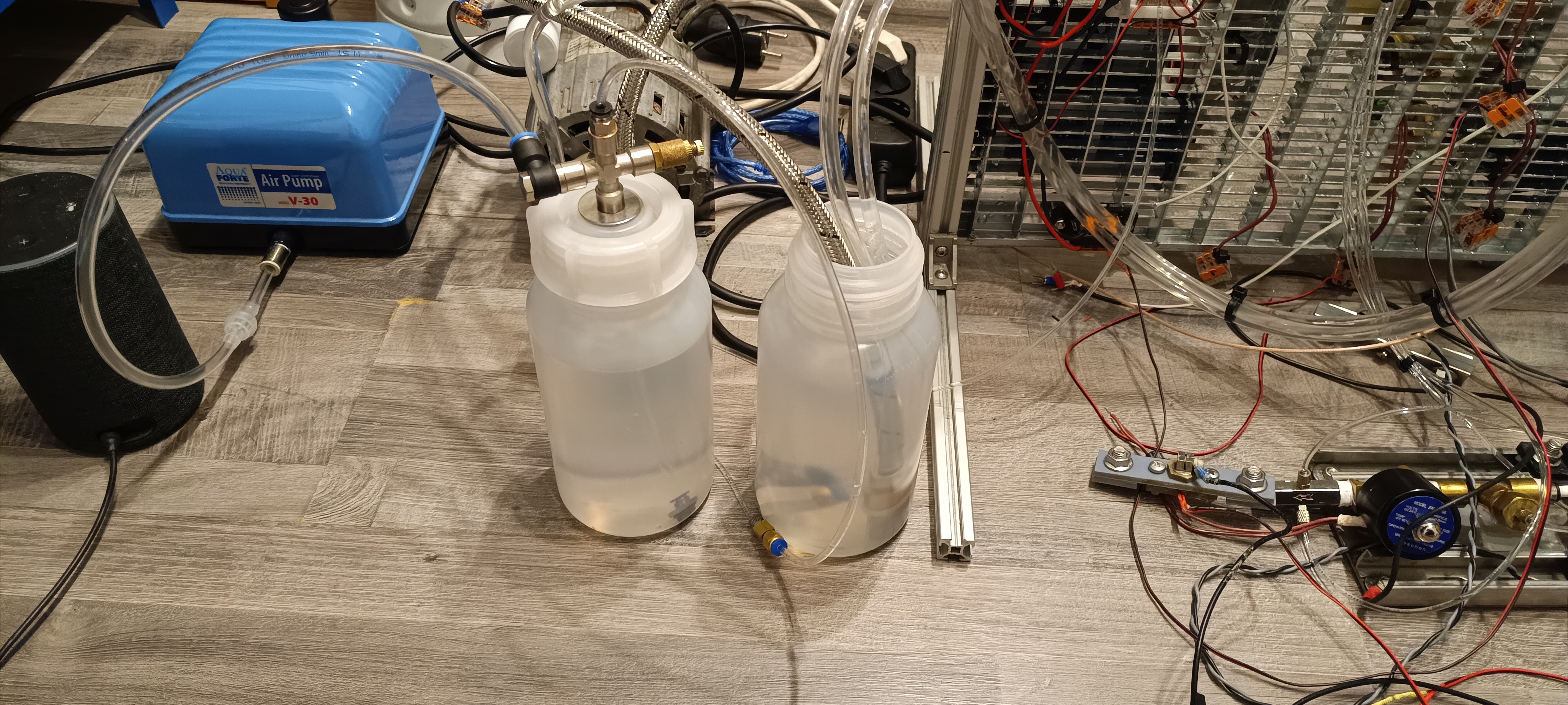
The pond air pump I mentioned at the start of this build log is used to pressurize the MakeUp (Solvent) bottle. This is done to make it easier to feed the MakeUp into the vacuum line and it's also used for cleaning the Nozzle with MakeUp.
Bottles for Ink and MakeUp
My current plan is to clean the nozzle at shutdown in an automatic process:
When the printer is turned off, first the ink to the nozzle is turned off. After enough time has passed to empty the gutter line, the vacuum to the gutter is turned off. Then the vacuum to the waste ink tank is turned on and the valve for cleaning the nozzle is opened to draw the ink from the nozzle into the waste ink tank. After some time has passed the vacuum to the waste ink tank gets turned off and the waste ink tank gets vented. Then the MakeUp valve gets turned on and a bit of pressurized MakeUp gets pushed through the nozzle to clean it. After some time the MakeUp valve gets turned off and the vacuum to the waste ink tank gets turned on for some time to dry the line from the nozzle to the waste ink tank.
When this is done, the nozzle should be clean and the ink pump + air pump should be turned off.
The waste ink tank also has a sensor to detect when it's full and a valve to drain it. I think I will keep the draining of the waste ink tank a manual operation to not accidentally spill the waste ink on the floor when no cup is placed under it.
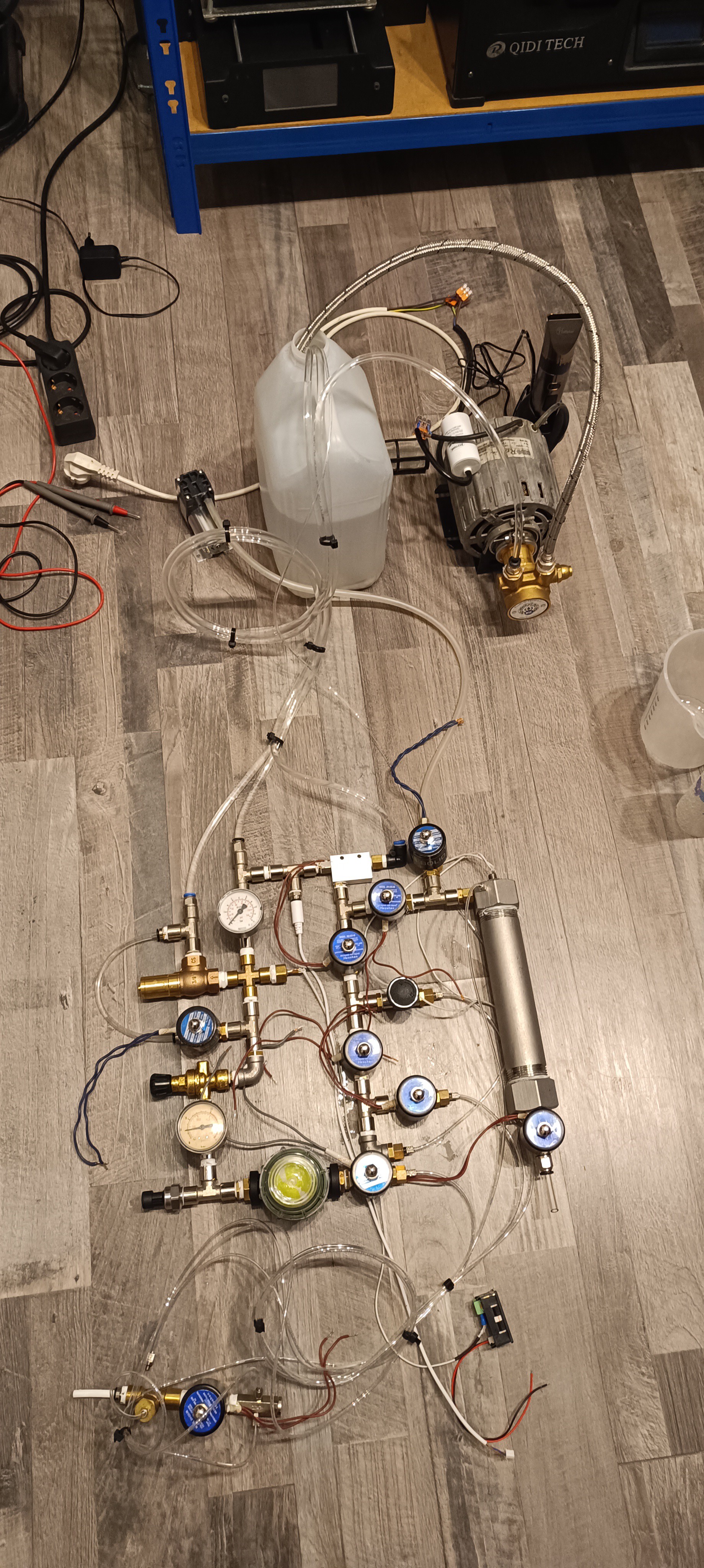
Latest Progress of the Printer
And this is it so far.
Currently, I have all valves and the waste ink sensor wired and the next thing is adding the viscosimeter back to the printer and connecting the temperature, conductivity, and pressure sensor to the Arduino.
When then everything is up and running, I can do a parts description and a building instruction for the fluid system of the new design.
I think this time I will keep the fluid system and the electronics for printing two separate things since the fluid system is mostly finished and there is still a lot of work to do on the printing electronics.
Thank you very much for your interest in my project :)
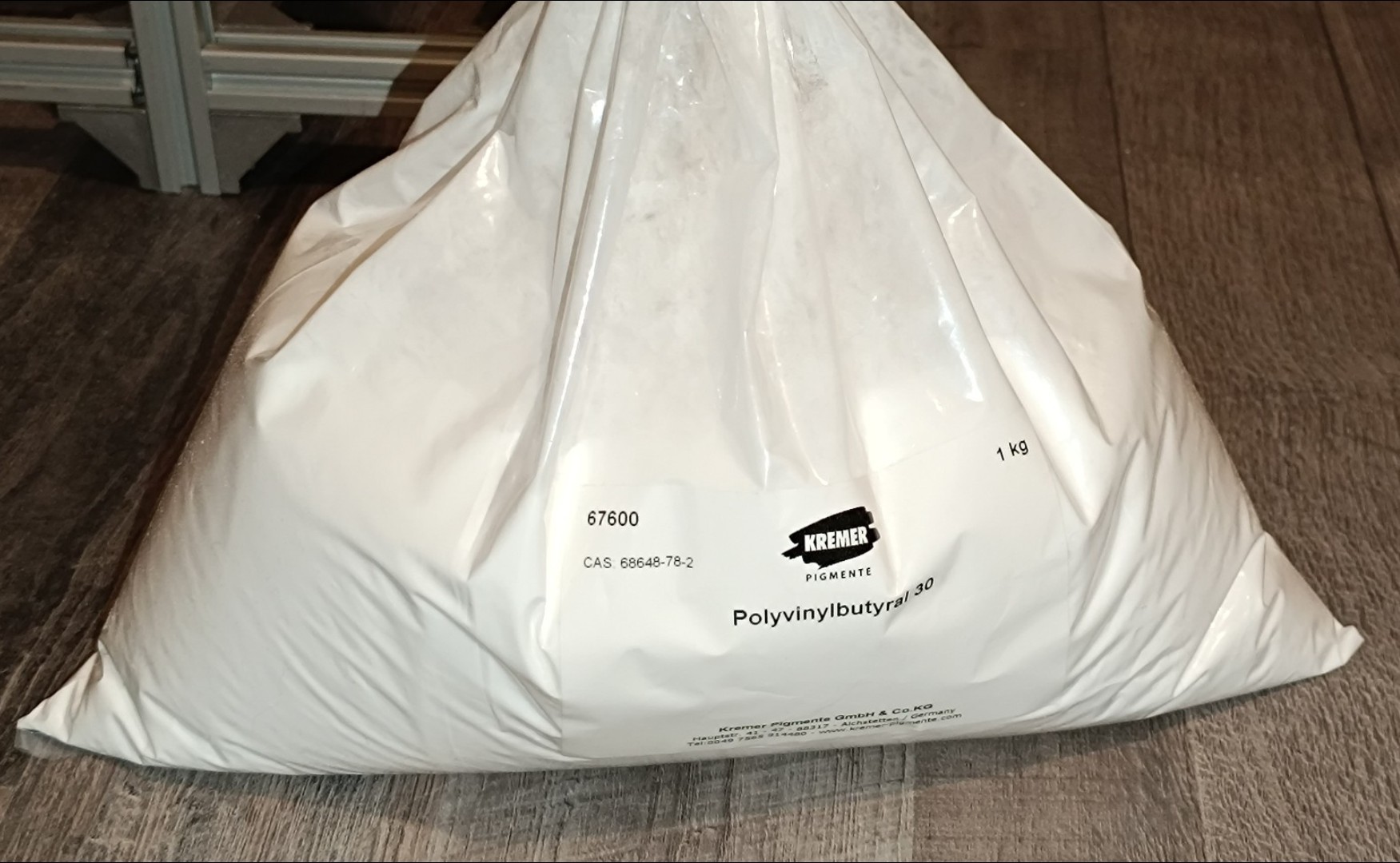
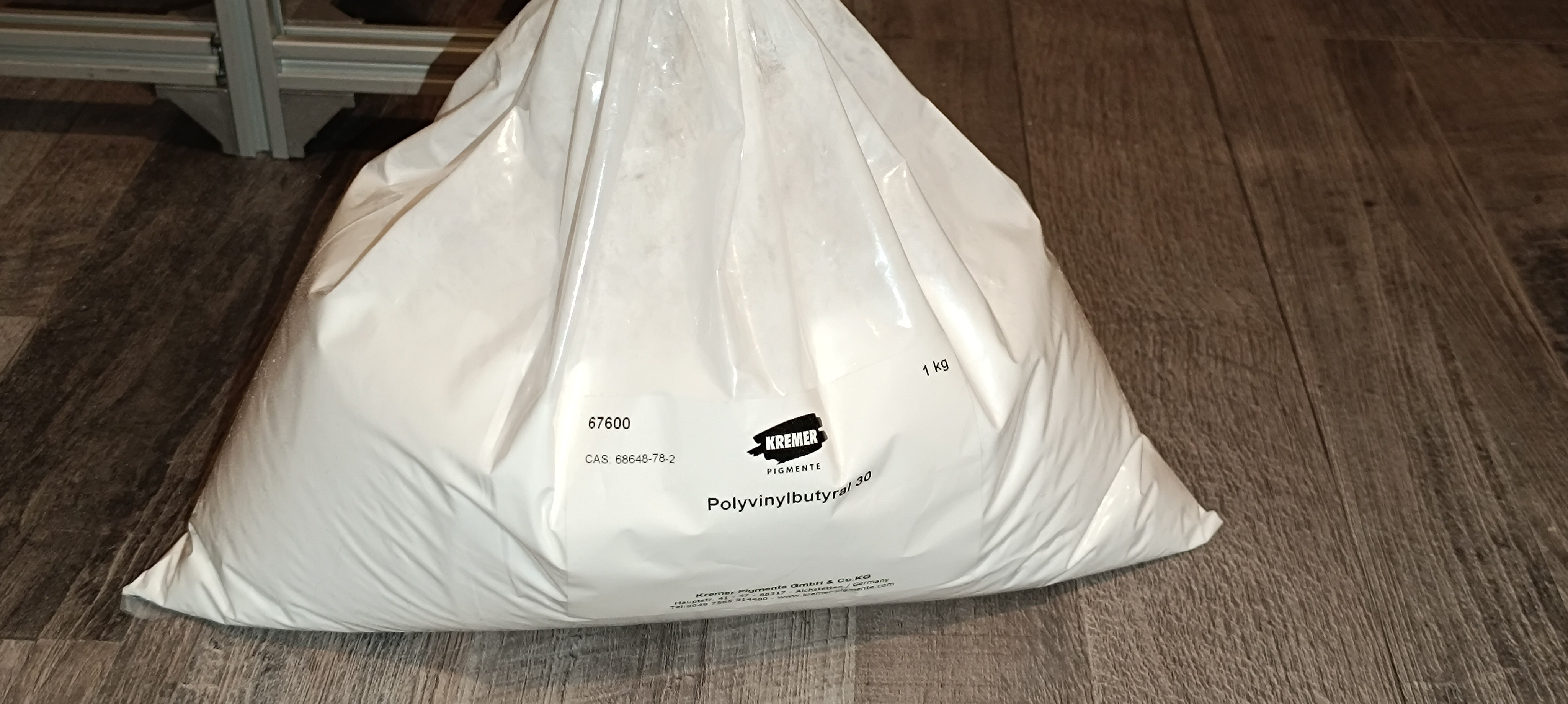
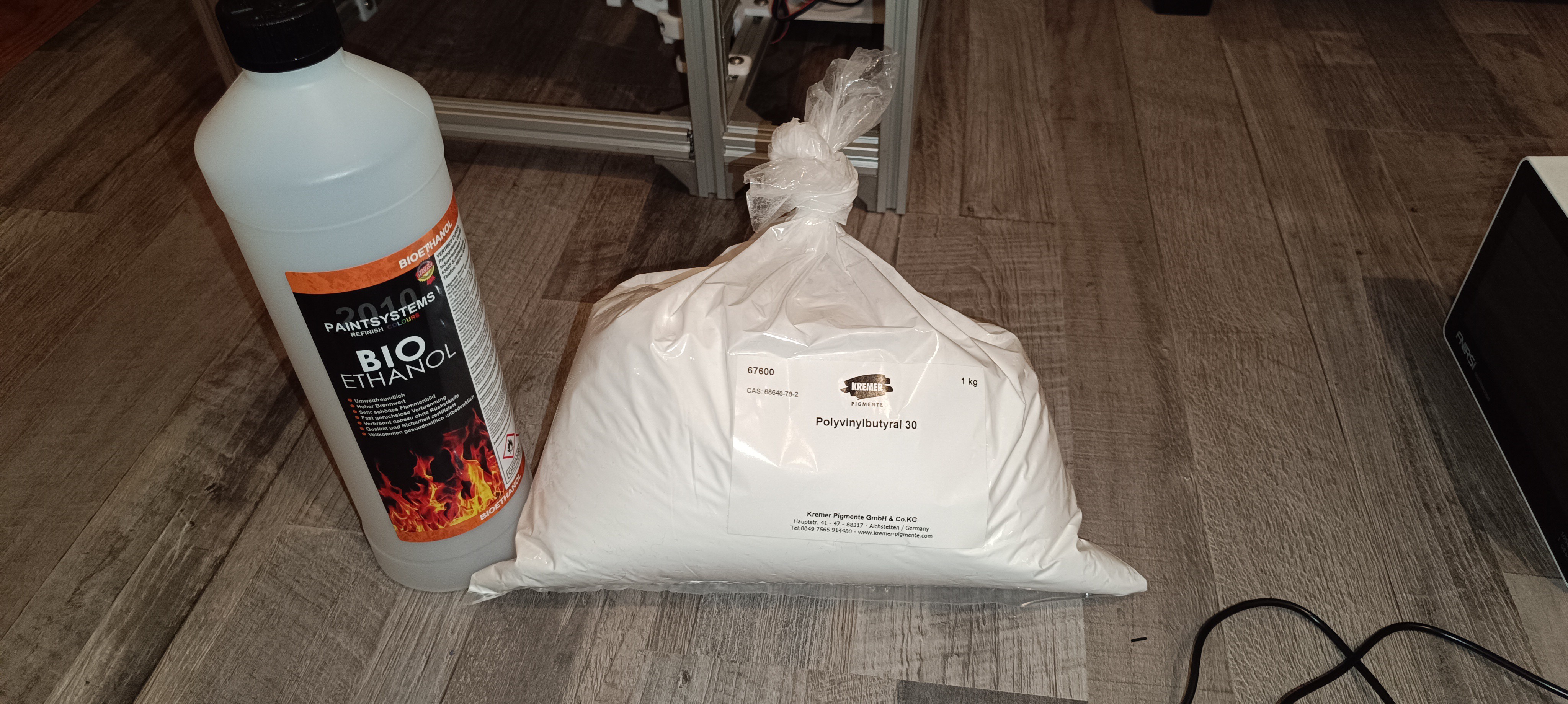
For the project, I'm currently using an ink made out of ethanol and polyvinyl butyral (PVB) with an additive for increasing its conductivity (sodium acetate).
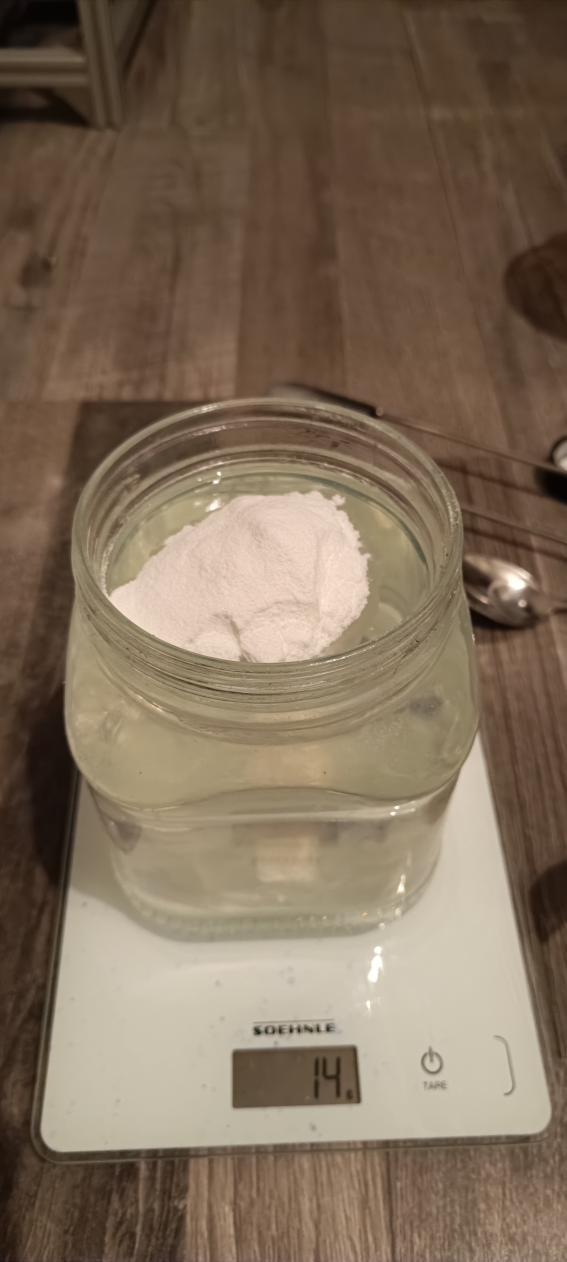
Until now, I used PVB powder for it and while it can be used for ink without problems, I'm still a bit concerned about using it, because it is not a commonly used item, so it can be a little hard to find a shop that sells it.
PVB Powder
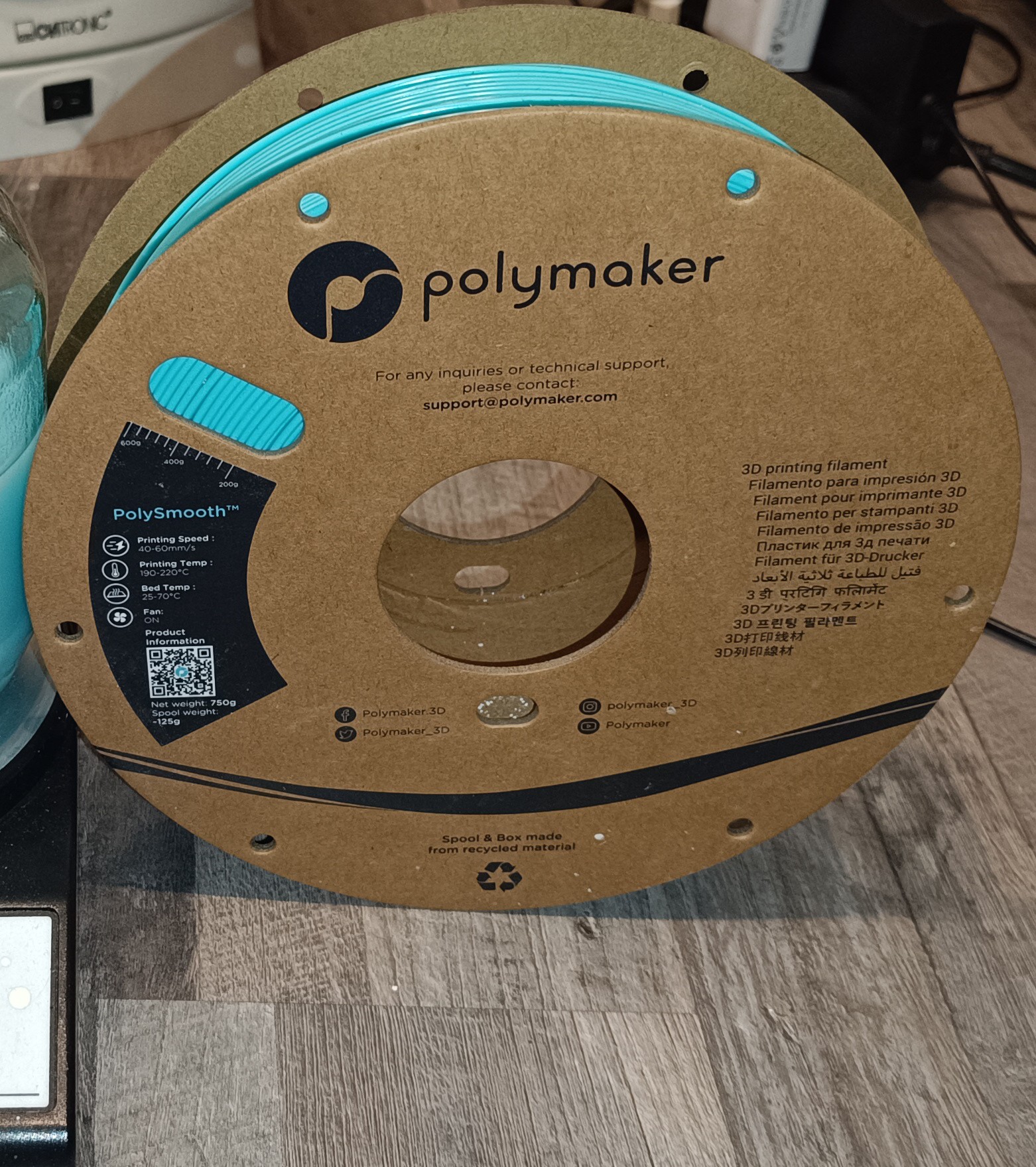
Because of that, I tried to find something else and saw that there is PVB-based 3D printing filament available almost everywhere you can buy filament.
So, I ordered a spool of PVB filament to test out if it dissolves in ethanol while increasing its viscosity.
PVB Filament (Polymaker Polysmooth)
For the test, I wrapped some filament around my hand and cut the windings together to get a few equal-sized pieces that could stand upright inside the cup like spaghetti noodles.
This way the filament dissolved better than when it was cut into shorter pieces or when PVB in powder form was used.
The shorter pieces stuck to the wall or bottom of the cup, and the powder formed clumps that only came in contact with the ethanol on the surface and stayed dry inside so it took a long time until they dissolved whitout constantly breaking them apart with a spoon.
At the same time, the longer pieces came in contact with the ethanol over the whole length and dissolved in about an hour without further ado.
Long Filament Pieces
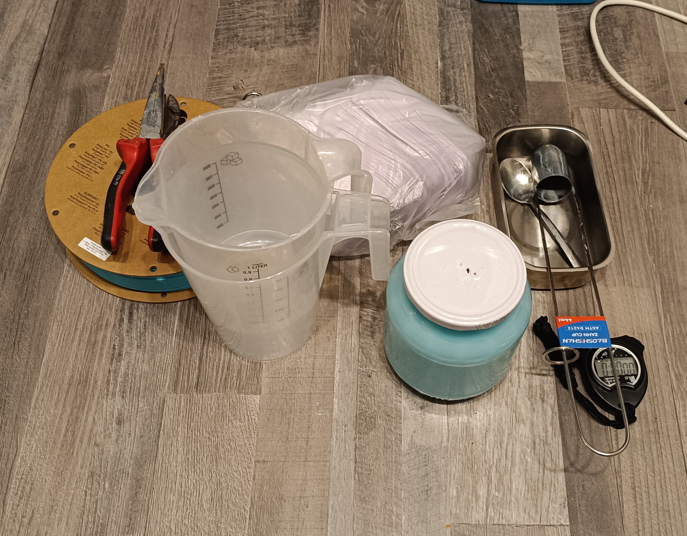
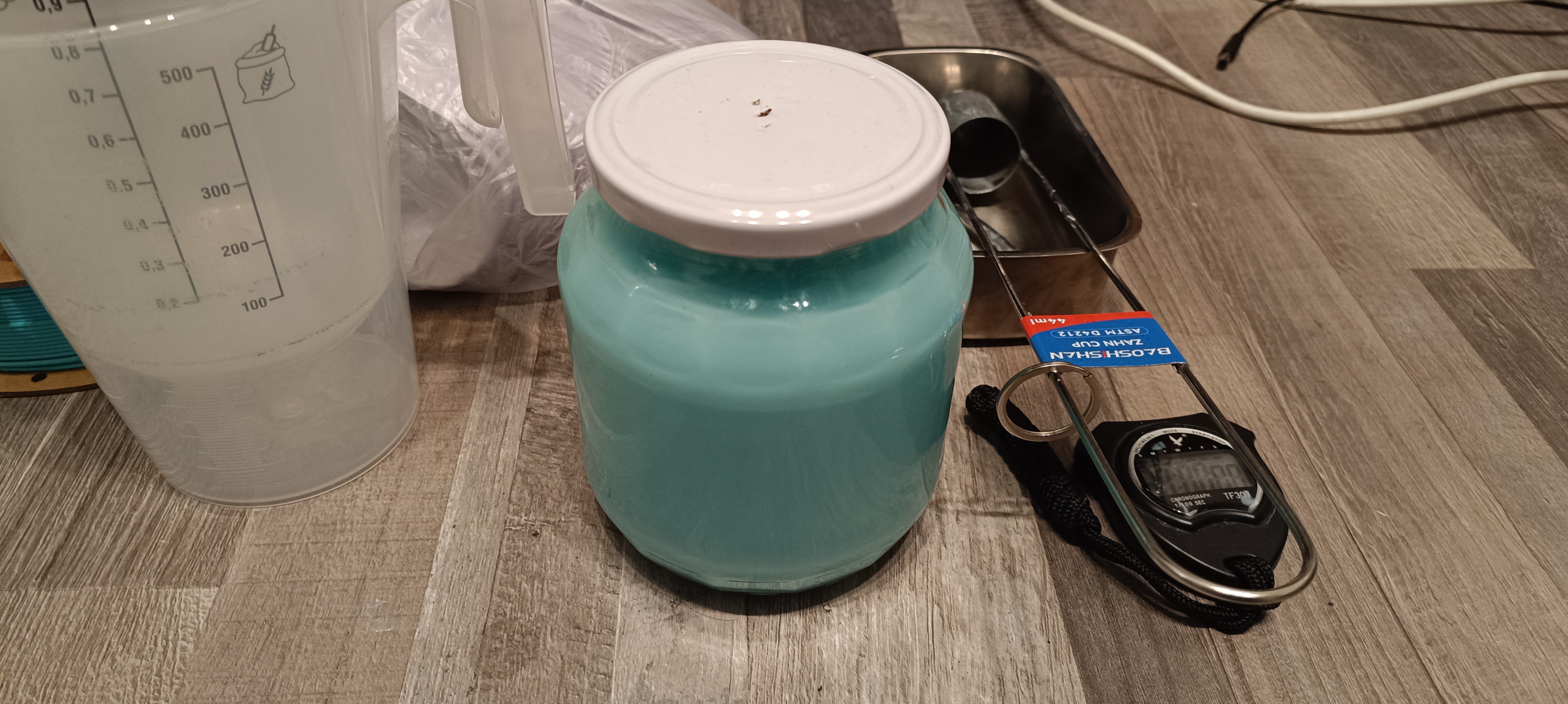
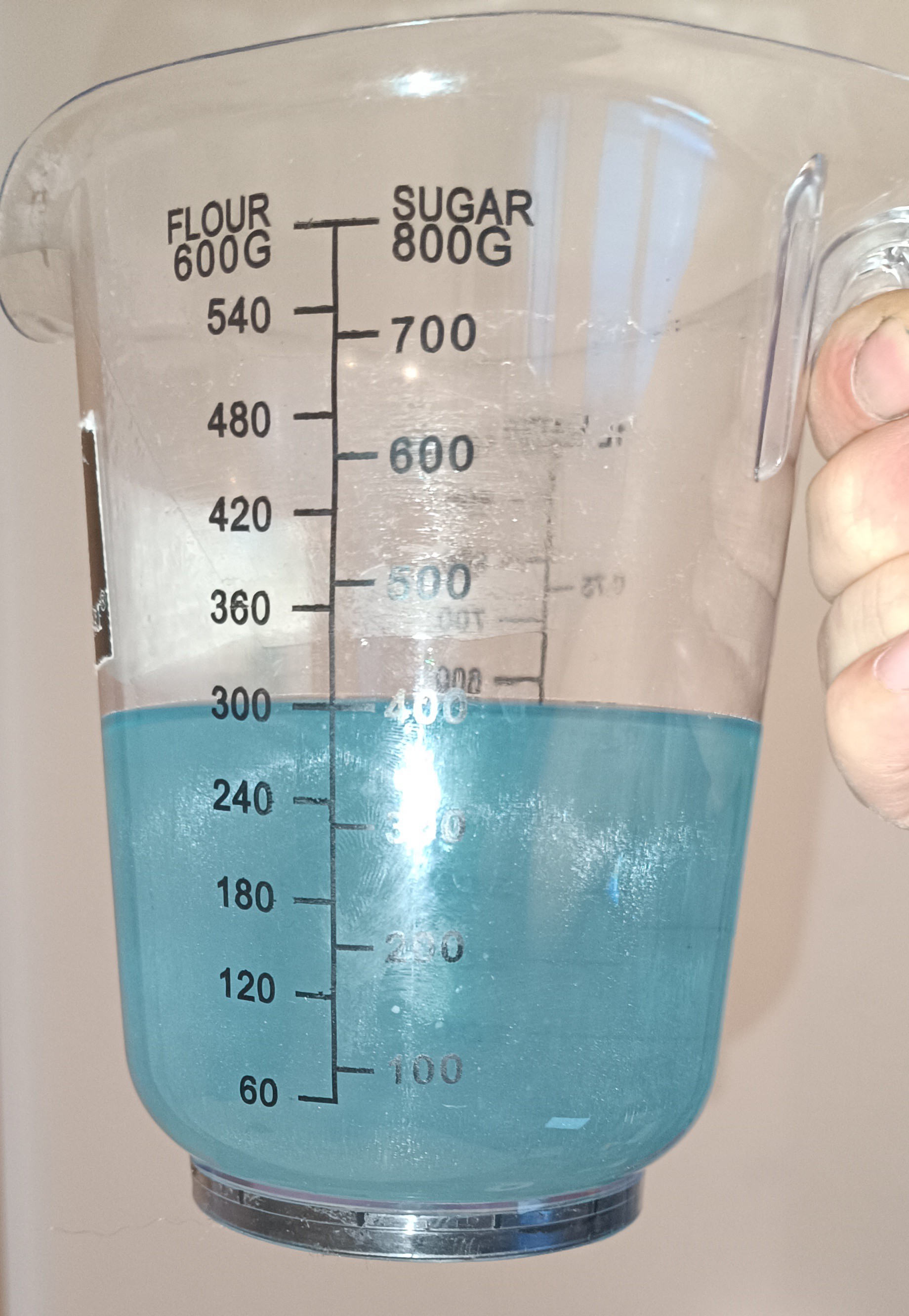
Filament Spool and Ink from Filament
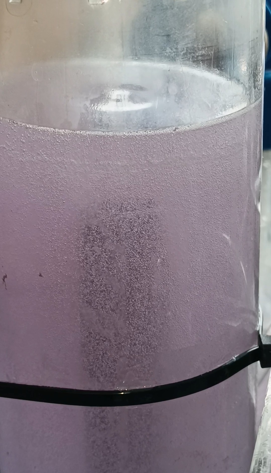
Filament and InkGlass with PVB Ink
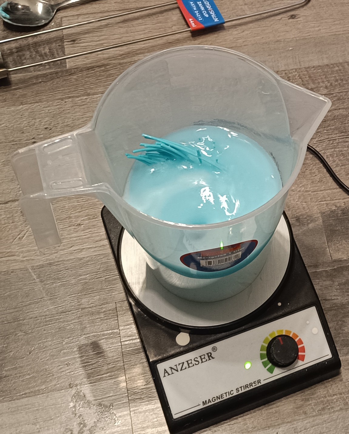
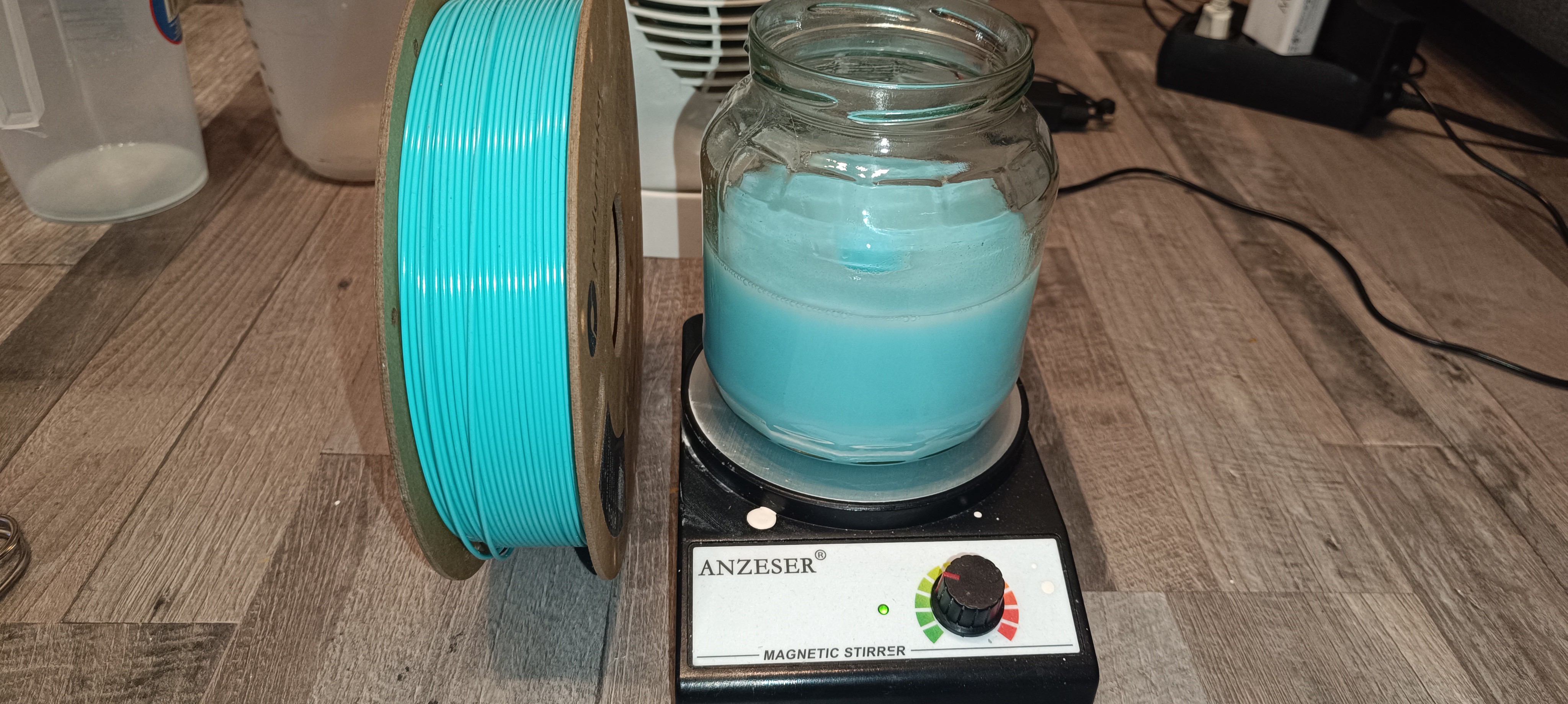
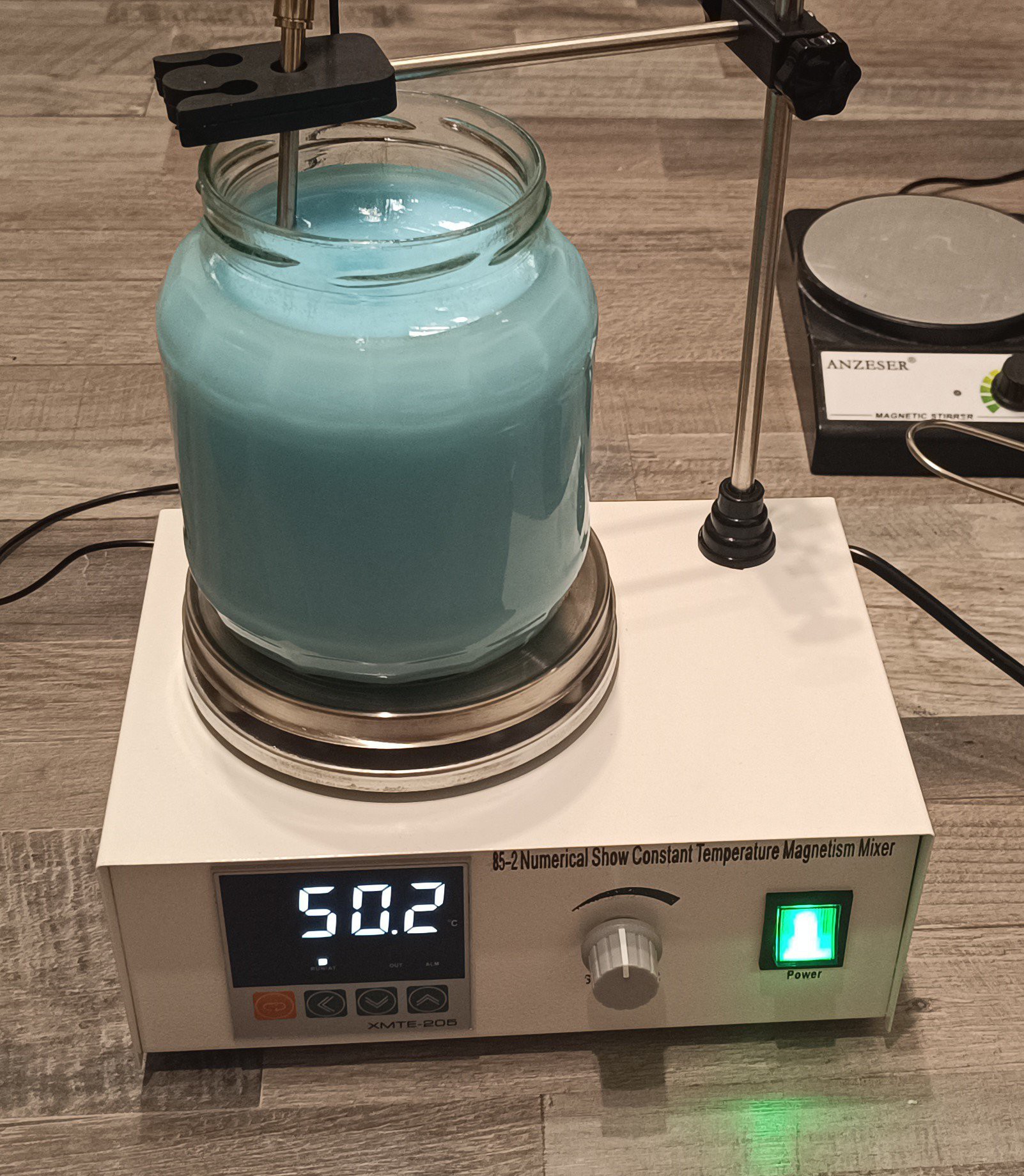
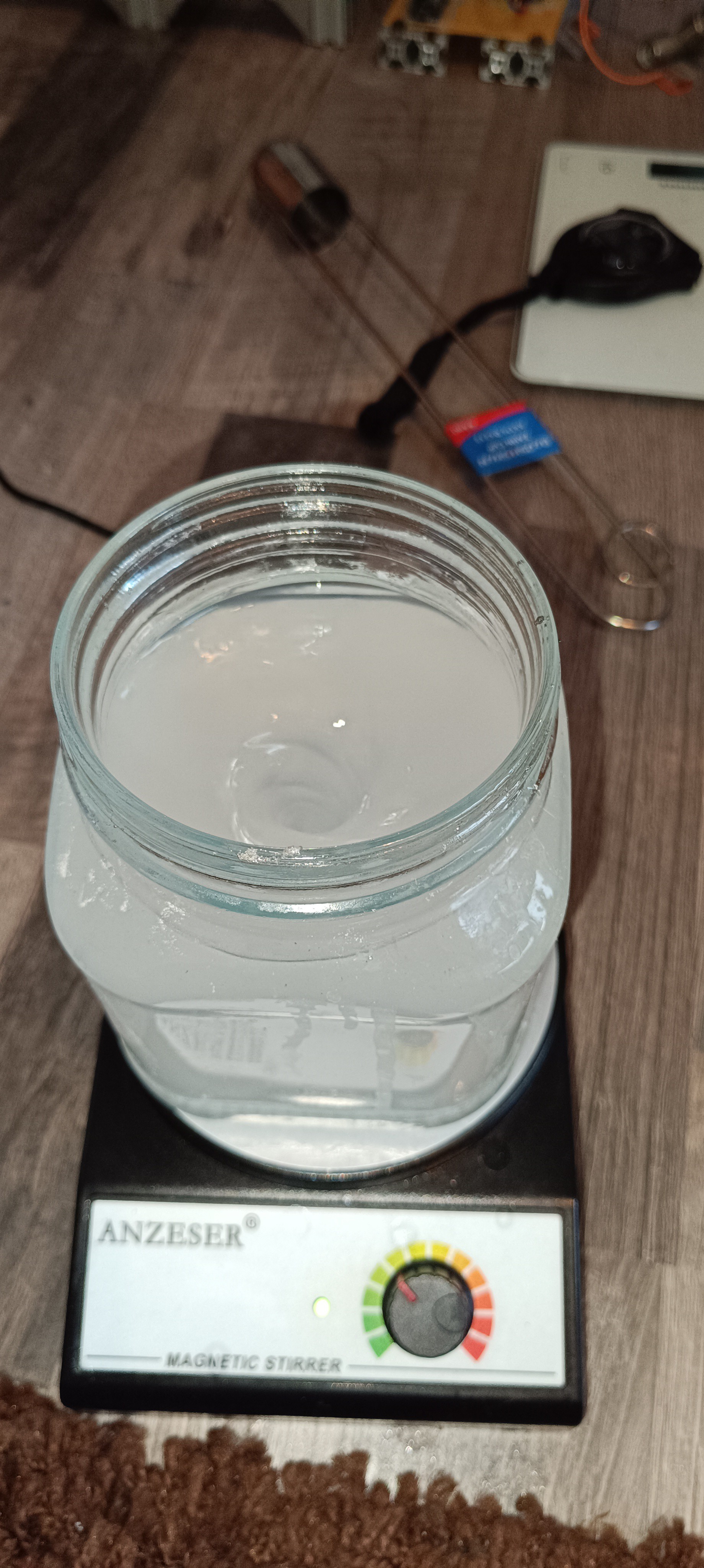
By heating the ethanol before adding the filament the time it takes to dissolve can be reduced even further.
PVB Ink on a Magnetic Stirrer with Heated Plate
After the filament was completely dissolved, I checked the viscosity of the mix with the Zahn 1 cup and saw that its viscosity had increased from around 26s of pure ethanol to over 30s with the filament mixed in.
It also gave the mix a nice color so that no separate color pigments were needed to add color to the mix. It could still be, that on paper it would appear rather white than blue since the color is not as intense as the color of ink pigments.
One disadvantage of the filament compared to the powder could be its purity. While the powder is only made out of PVB, the filament may also contain other substances that could clog the nozzle or the filter, so it's important to keep an eye on that.
Overall, I think the PVB filament can be used to mix PVB ink and if it's easier to get than PVB powder it should be an suitable alternative.
Great thanks to Robert and @Paulo Campos for helping me with this :)
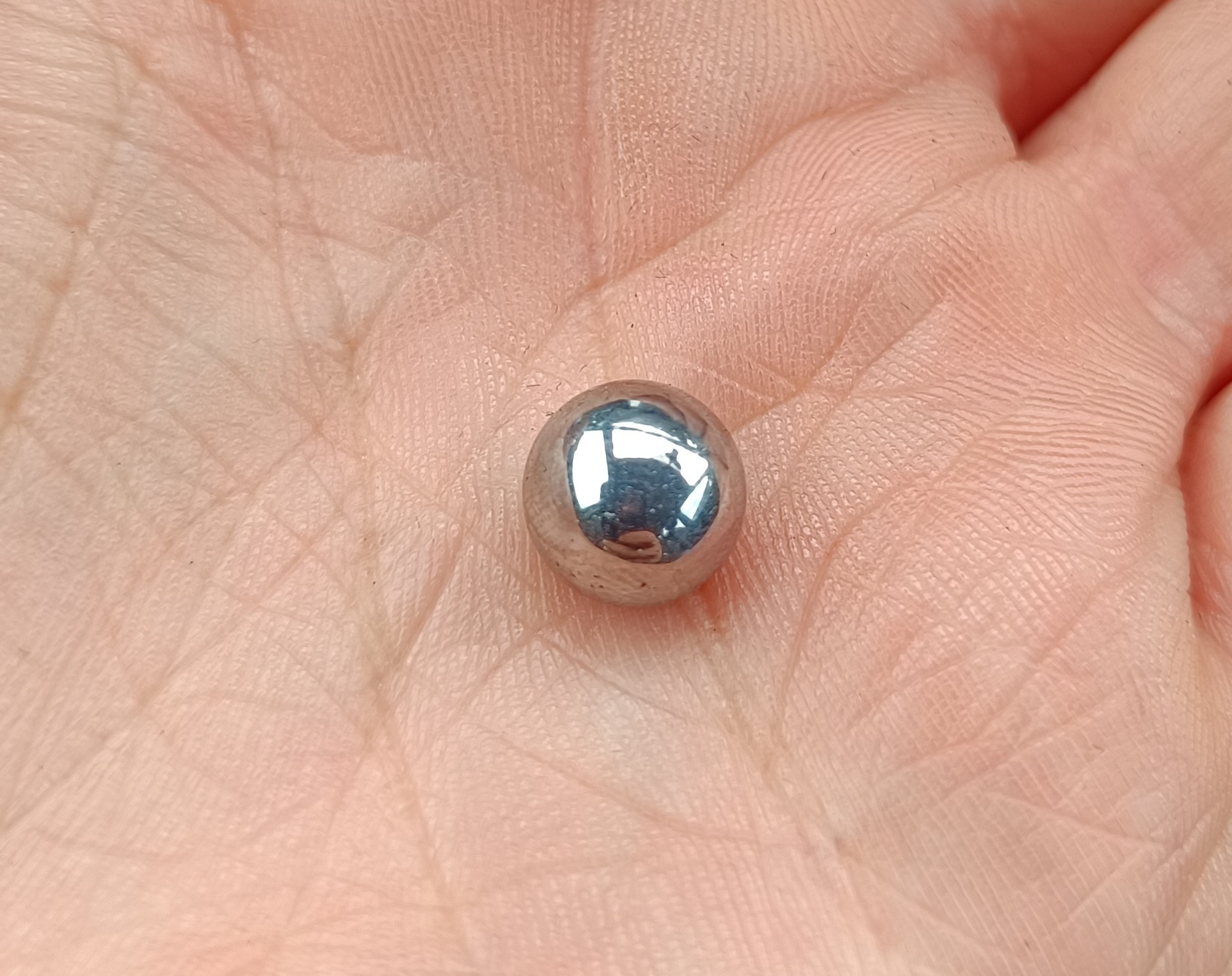
To measure the viscosity of the ink more reliably I replaced the drain time counter with a falling ball viscosimeter, another viscosity measuring method that is also used by many commercial CIJ printers.
9mm Steel Ball
The falling ball viscosimeter works by counting the time a (steel) ball takes to fall a certain distance inside a tube that is filled with the fluid of which the viscosity should be measured.
The size and weight of the ball and the distance never change, but the time reading will change with viscosity. The fall time increases when the viscosity gets higher and decreases when the viscosity gets lower.
I did a lot of testing with it and as long as the fluid inside the tube doesn't move, the time readings are quite stable.
Here is my progress on it in chronological order:
I had the idea of building it in late AugustPossible mounting LocationFirst Prototype
First test of the Viscosimeter
Prototype with Electromagnet Lifter and Stepper Motor
Test of the Stepper Motor Lifter
Testing out a Pump for lifting the Steel Ball
Test of the Pump Lifter
Viscosimeter with optical Switches and new Tube
Test of the optical Sensors and Pump
PVB for increasing ViscosityEthanol and PVB
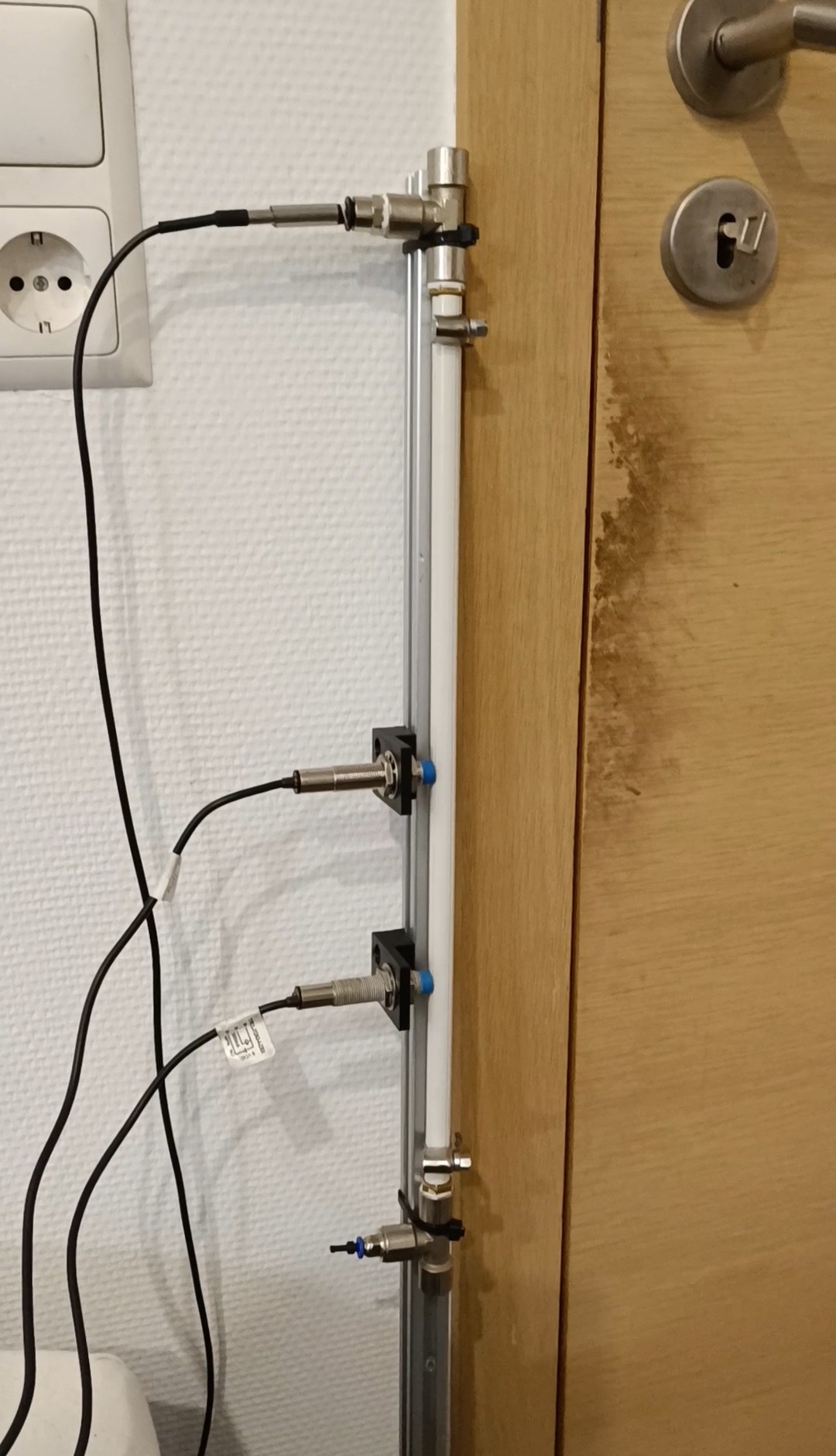
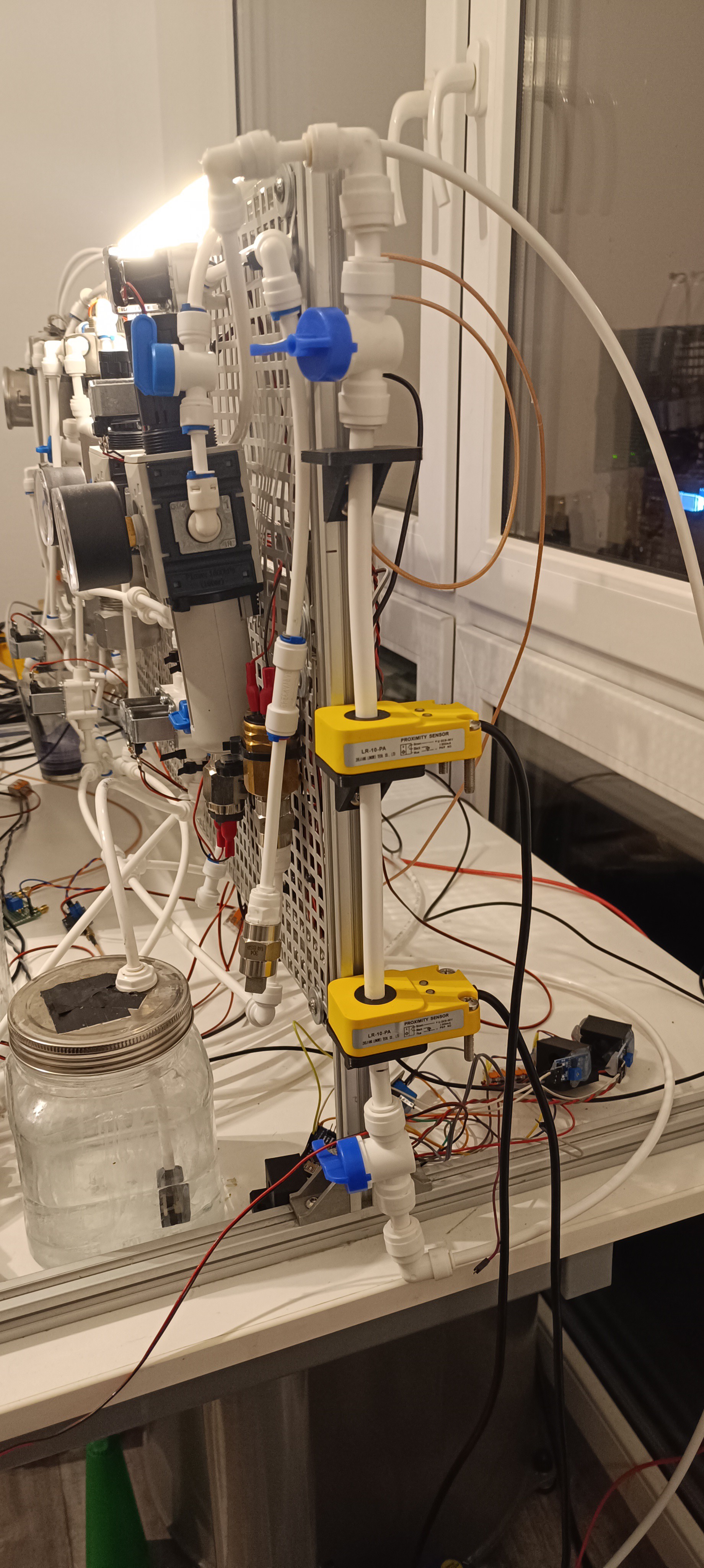
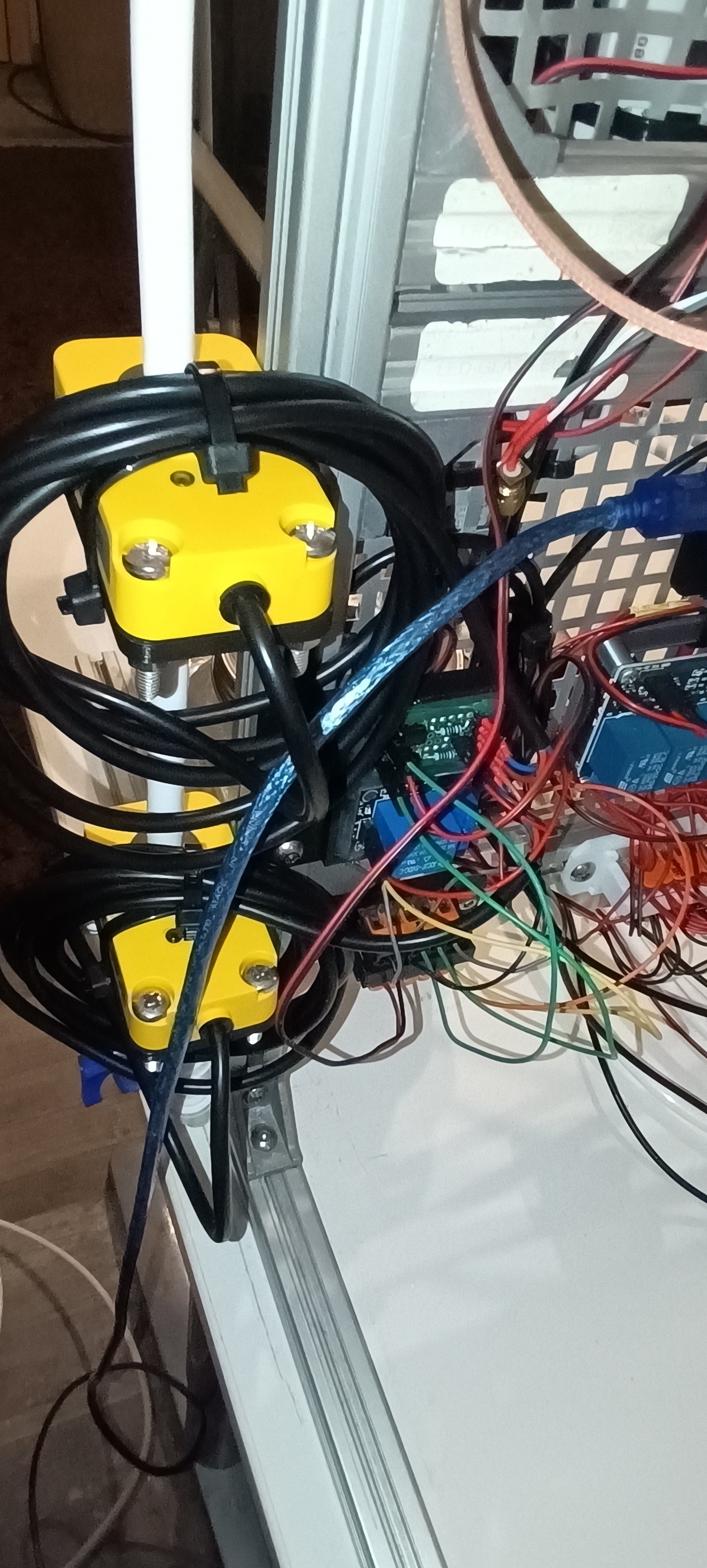
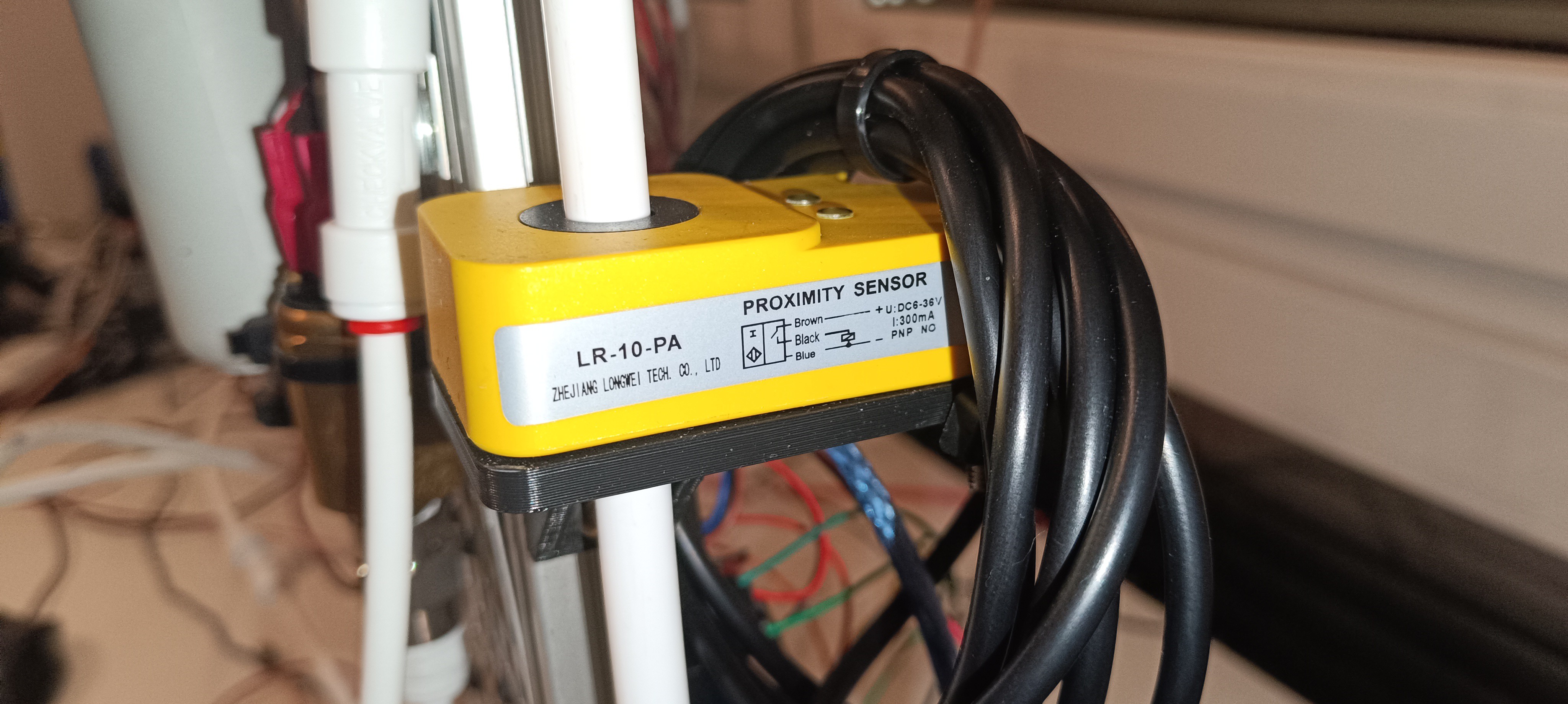
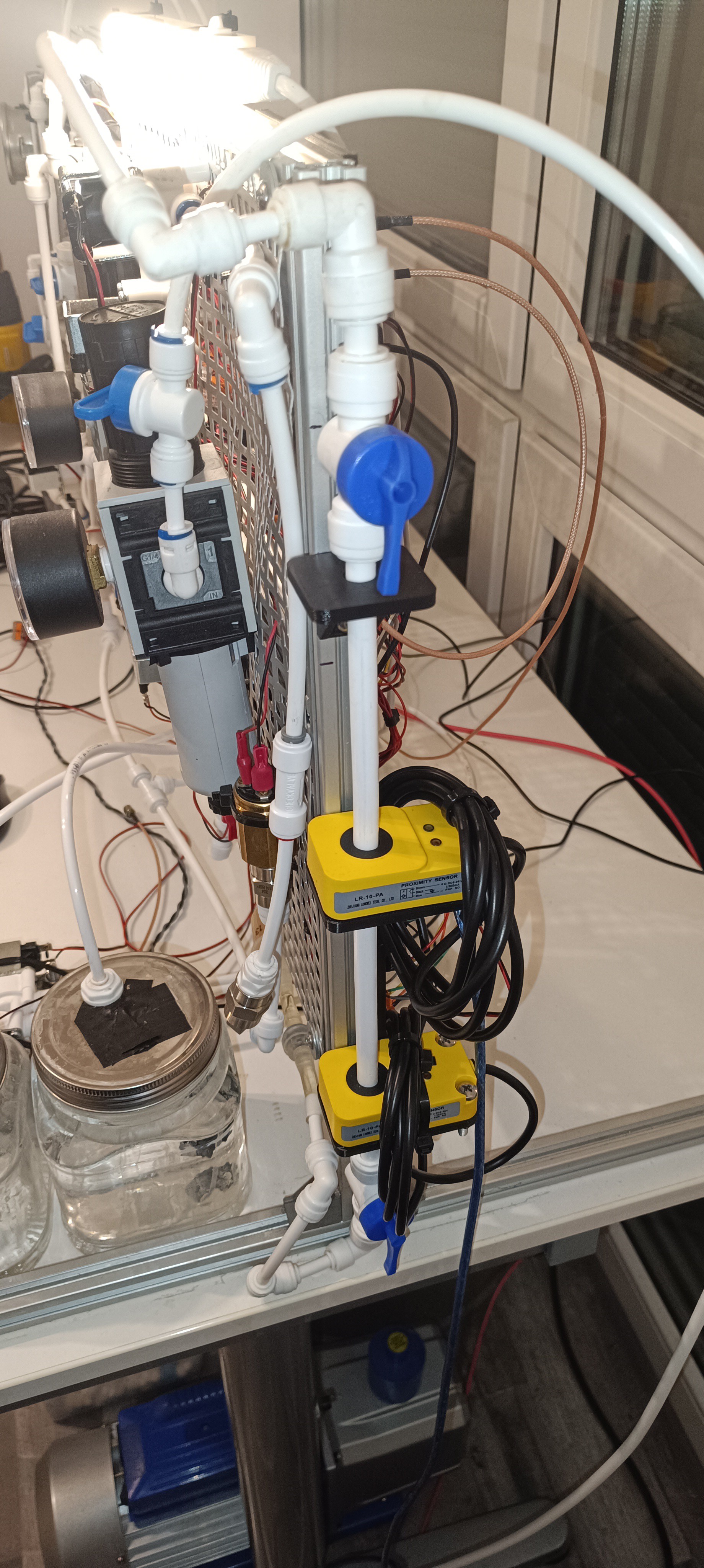
Standalone Falling Ball Viscosimeter for Long Term Testing of different ViscositiesNew inductive Proximity Sensors
Finished Viscosimeter
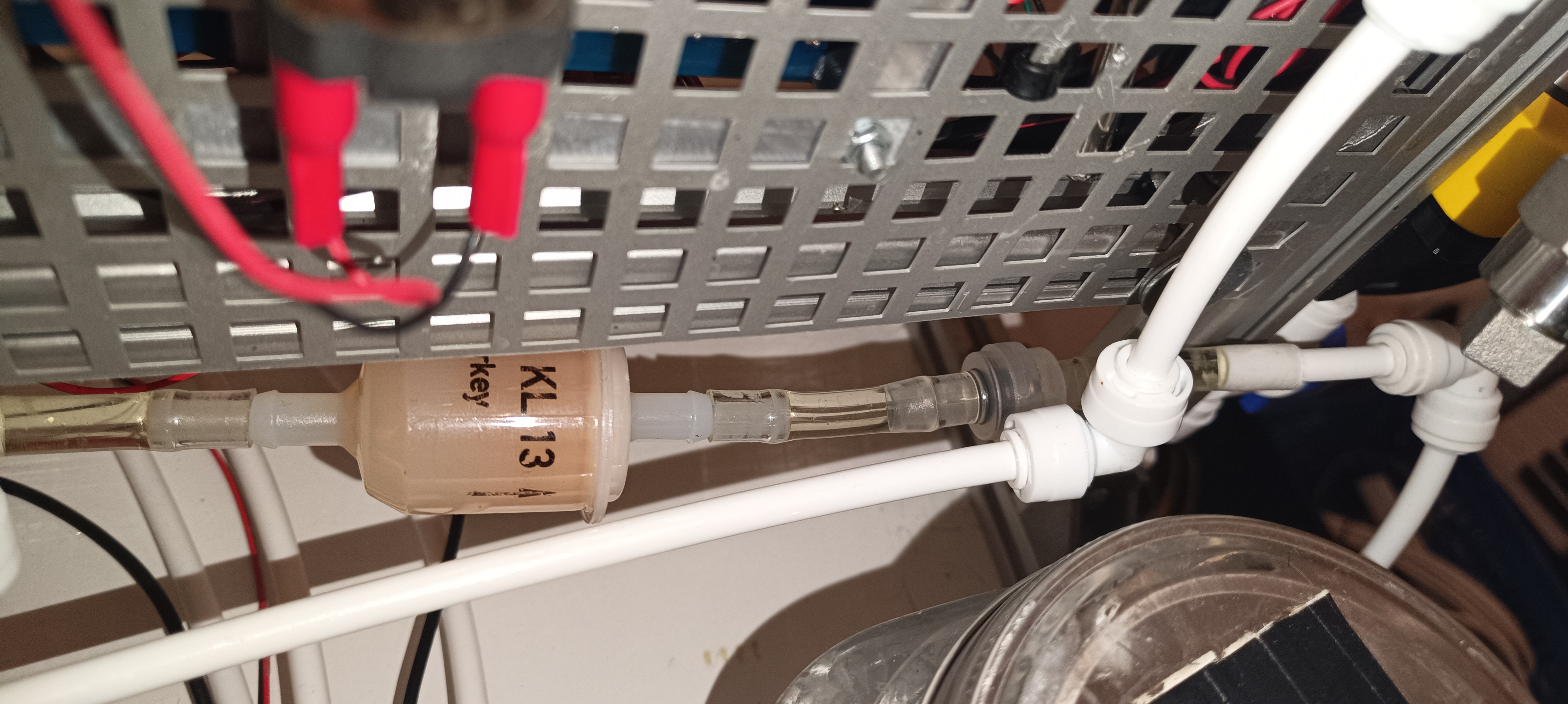
Filter and Check Valve to prevent Backflow
Relay for the Pump and Optocouplers for using the 12V Inductive Sensors together with an Arduino
I didn't cut the Cables - To keep the Sensors ready for possible Modifications of the Setup in the Future
Sensor Type and Pinout on the Label
View from the Side
Small Gear Pump for lifting the Steel Ball
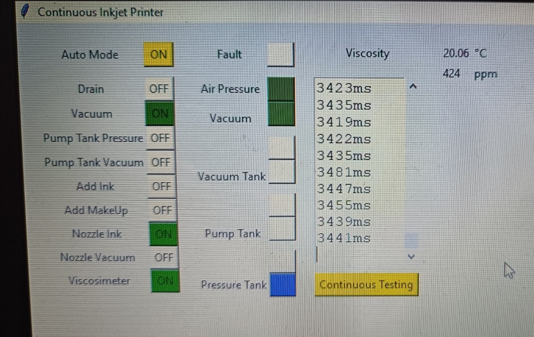
6mm Steel Ball used in the 3/8 inch PE Tube if the ViscosimeterViscosimeter implemented into the GUI Continuous Testing - No Pause between Readings
In commercial CIJ printers, the viscosimeter is calibrated by selecting the ink type that is used and doing some test readings with it. Based on the test readings the printers can calculate the relation between measured time and viscosity. This is possible because the exact viscosity of the used commercial ink type is known and always the same. Over time, some of the solvent in the ink bottle can evaporate which increases viscosity, so it's recommended to always use a fresh ink bottle for calibration. With the right calibration, the printers can show the actual kinematic viscosity reading in cPs.
In theory, it would be possible to use this method for this DIY CIJ printer - ordering some ethanol based CIJ printer ink and using it for calibrating the viscosimeter. The problem with it, besides the high price of CIJ printer ink, is that the ink's viscosity is not shared with the public so there would be no reliable values for calculation. It's stated that the ink's viscosity is usually around 5 cPs, but for calculating a precise conversation value it would be no bad idea to get the exact viscosity from the ink's manufacturer. With some luck, it could still be possible to find one ink that has a datasheet that mentions its viscosity. In this case, this ink could easily be used for calibrating the viscosimeter and also for printing if the price tag doesn't make it unattractive compared to self mixed ink.
Another way would be buying some calibration oil (oil with known viscosity) which probably could provide reliable values for calculation. The problem with it would be that for the calibration all lines would have to be cleaned from ink, then filled with oil for calibration, then cleaned again, and then filled with ink again to prevent mixing of both fluids and contamination of the ink. So, with some effort, this could also be a way to get readings in cPs from the viscosimeter.
If no ink or oil is used for calibration it should also be possible to find out the optimal viscosity by keeping the ink pressure steady and looking at the feedback signal while increasing and decreasing the viscosity. The breakup and charging should be the best at the optimal viscosity and should get worse when it's too high or too low. This way it should be possible to only use the time reading of the viscosimeter without calibration.
My personal guess would be that the time count will be enough to keep the printer working.
I'm currently working on the feedback signal analysis and also looking if I can replace the pneumatic based setup with a pump based setup to reduce the complexity of the printer.
Keeping the ink at the right viscosity is essential for getting a stable ink stream breakup and with that stable charging and deflection of the ink droplets.
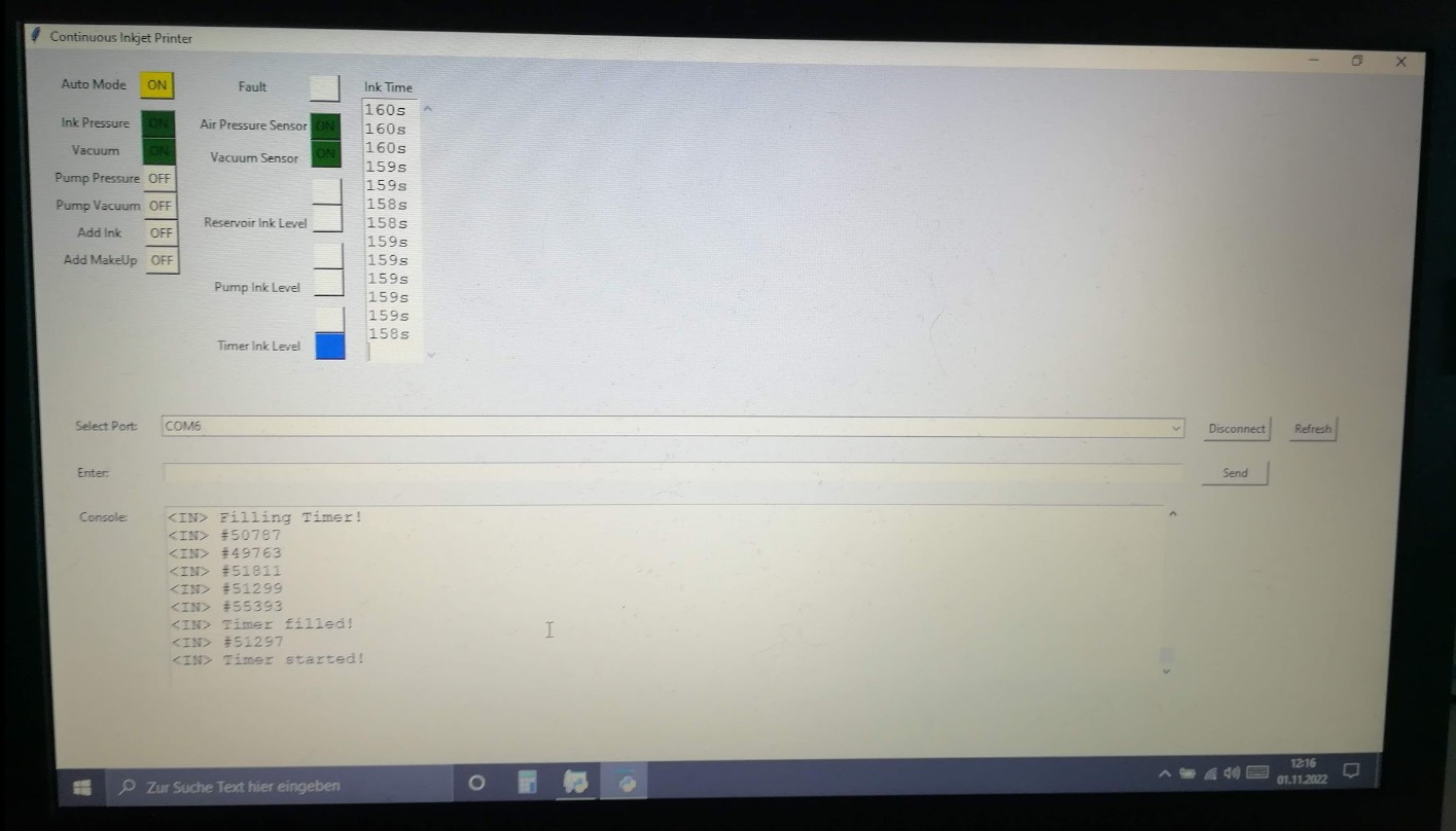
In the initial design, I counted the time it takes until the ink level of the pressurized tank has dropped from full to empty.
Counter added in November 2022
After using just tap water for a while I tried using Vegetable Glycerin instead of water since it has a higher viscosity.
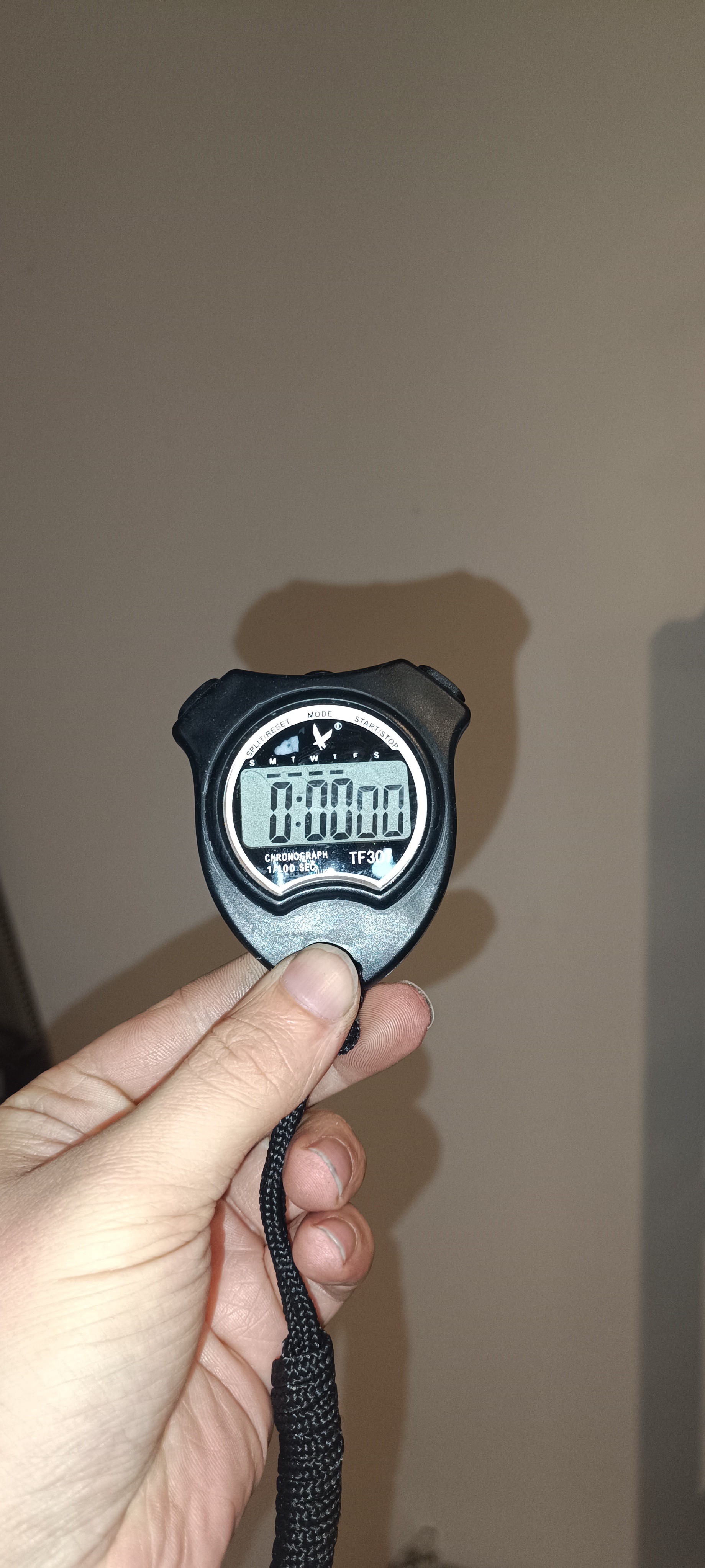
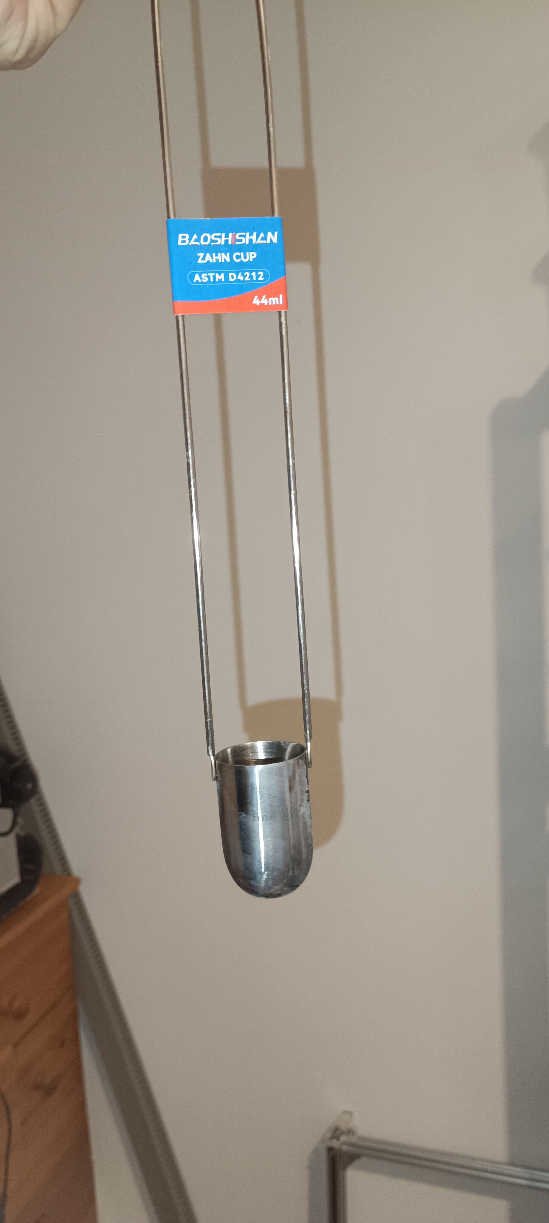
To measure its viscosity and compare it to the drain time counter I got a Zahn Cup 1 and a Stopwatch.
Stopwatch for counting the drain time of the Zahn Cup
Zahn Cup 1
These cups have a hole on the bottom for fluid to leak out and are used by completely submerging them into a fluid, then lifting them and counting the time until the solid fluid stream from the bottom of the cup starts dripping.
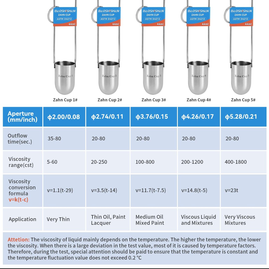
By using the corresponding conversation formula, it's possible to calculate the kinematic viscosity of the measured fluid.
Chart for calculating Kinematic Viscosity
While testing I saw, that the values lined up to some point:
When I added VG to the water, the drain time got longer, when I added water the drain time got shorter.
It worked ok, but since I'm constantly changing parts of the fluid lines that are filled with ink it's hard to prevent that some of it hits the desk or floor, and because Vegetable Glycerin is an oily fluid that not evaporates (in contrast to water), it turned out to be pretty messy to work with and I switched back to water after this test.
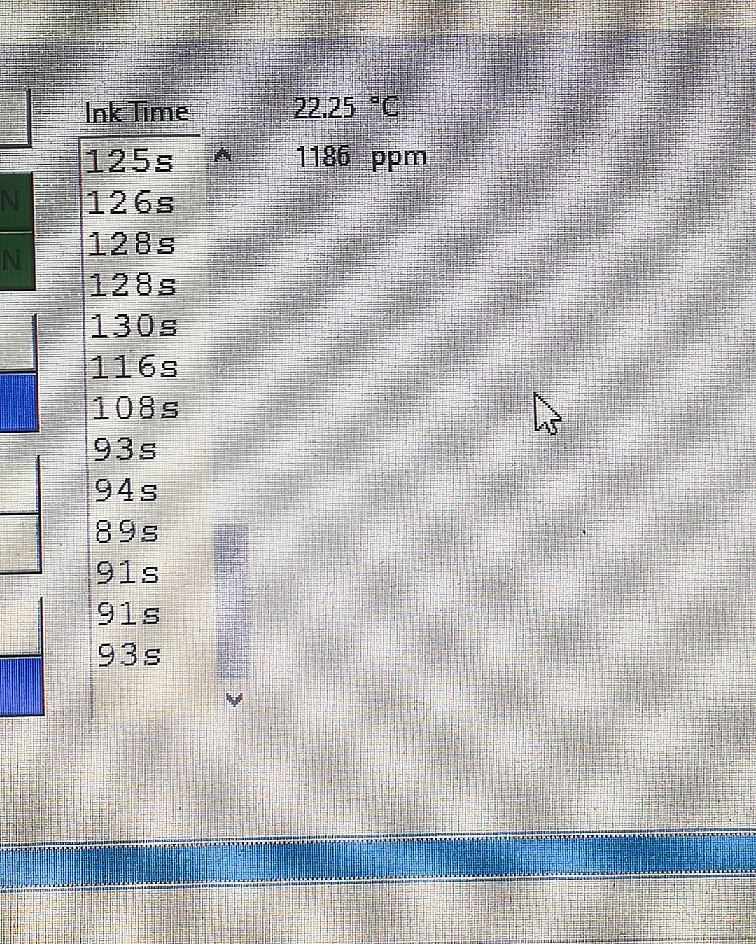
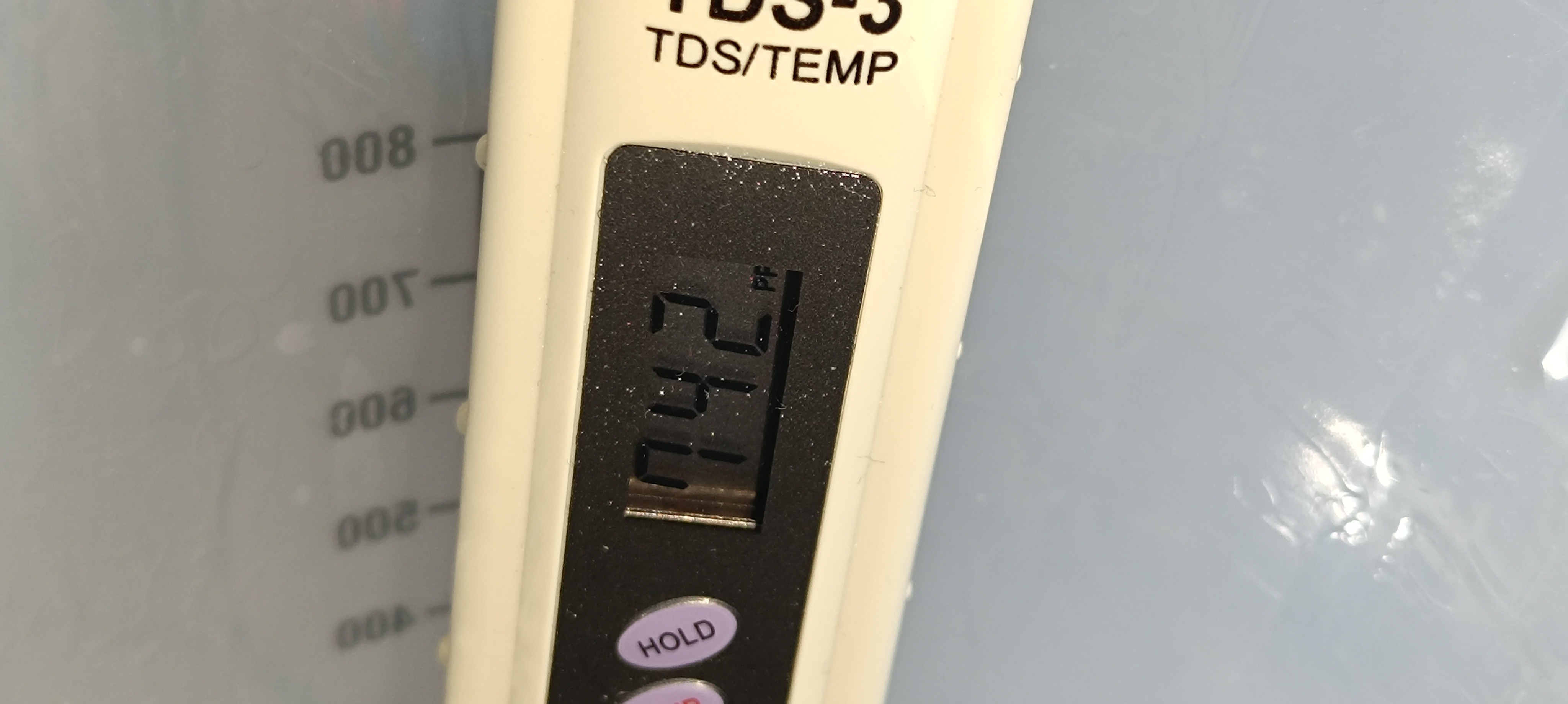
The next update to the printer was adding a PPM meter and a temperature sensor for measuring conductivity and temperature.
Since viscosity changes with temperature, I thought it would be a good idea to not only keep track of the viscosity but also of the temperature.
Temperature in ⁰C, Conductivity in ppm
While the conductivity is not related to viscosity it's still important because the ink needs to be conductive for charging.
PPM sensor on the left, temperature sensor on the rightPPM Sensor Amplifier
To increase conductivity I used different additives over time:
For water, I tried out:
- Table Salt
- Baking Soda
- Citric Acid
- Cleaning / Washing Soda
- Sodium Propionate
- Fountain Pen InkFountain Pen Ink mixed with Water for increasing Conductivity and for adding Color to the Ink
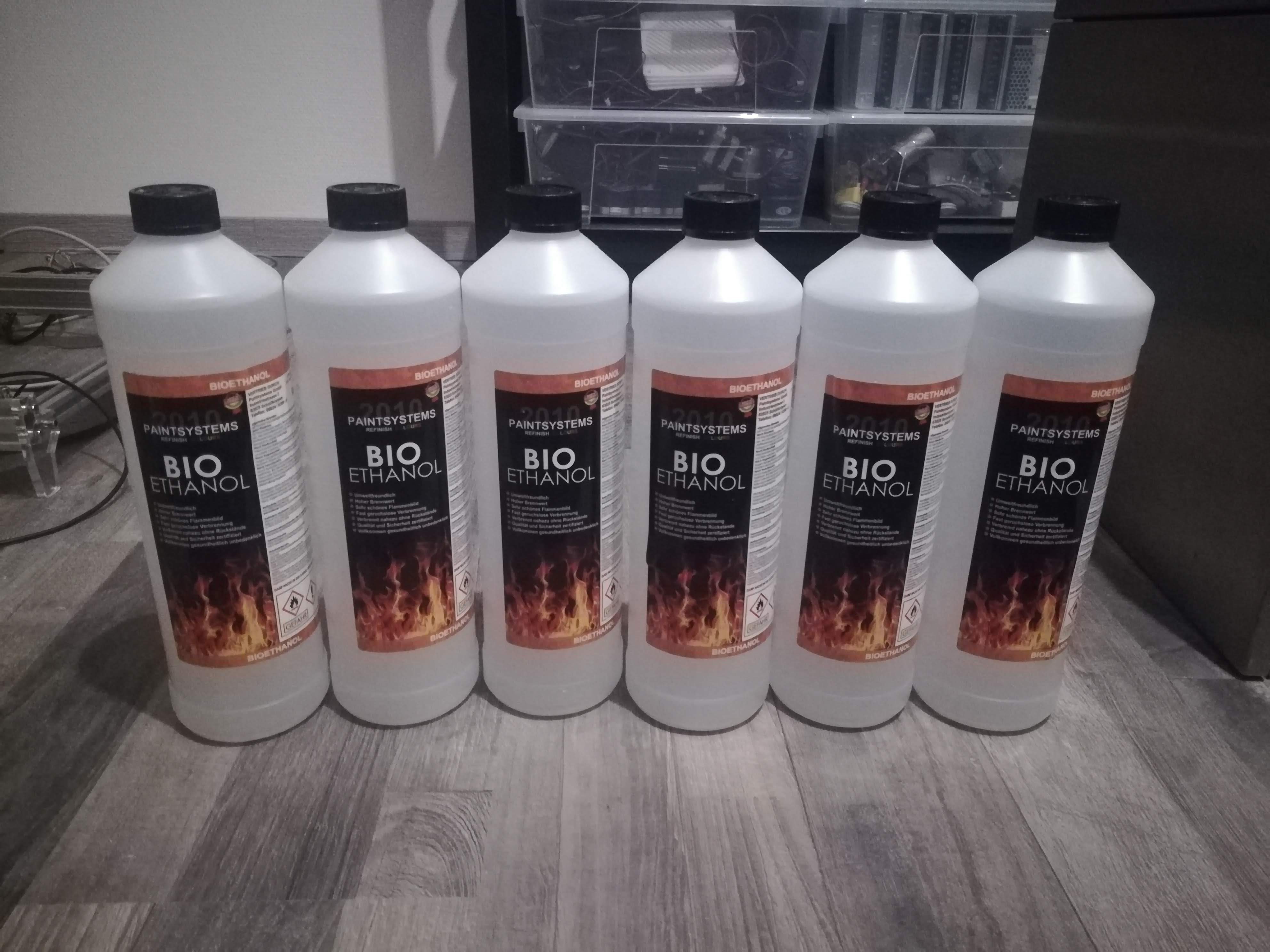
There are likely many more additives that are soluble in water, but since I switched from water to ethanol to get a fast drying and water resistant ink, I didn't test out more of them.
Bio Ethanol - Normally used for Heating
Since not every salt that is well soluble in water is also well soluble in ethanol, it was needed to start searching for ethanol soluble salts.
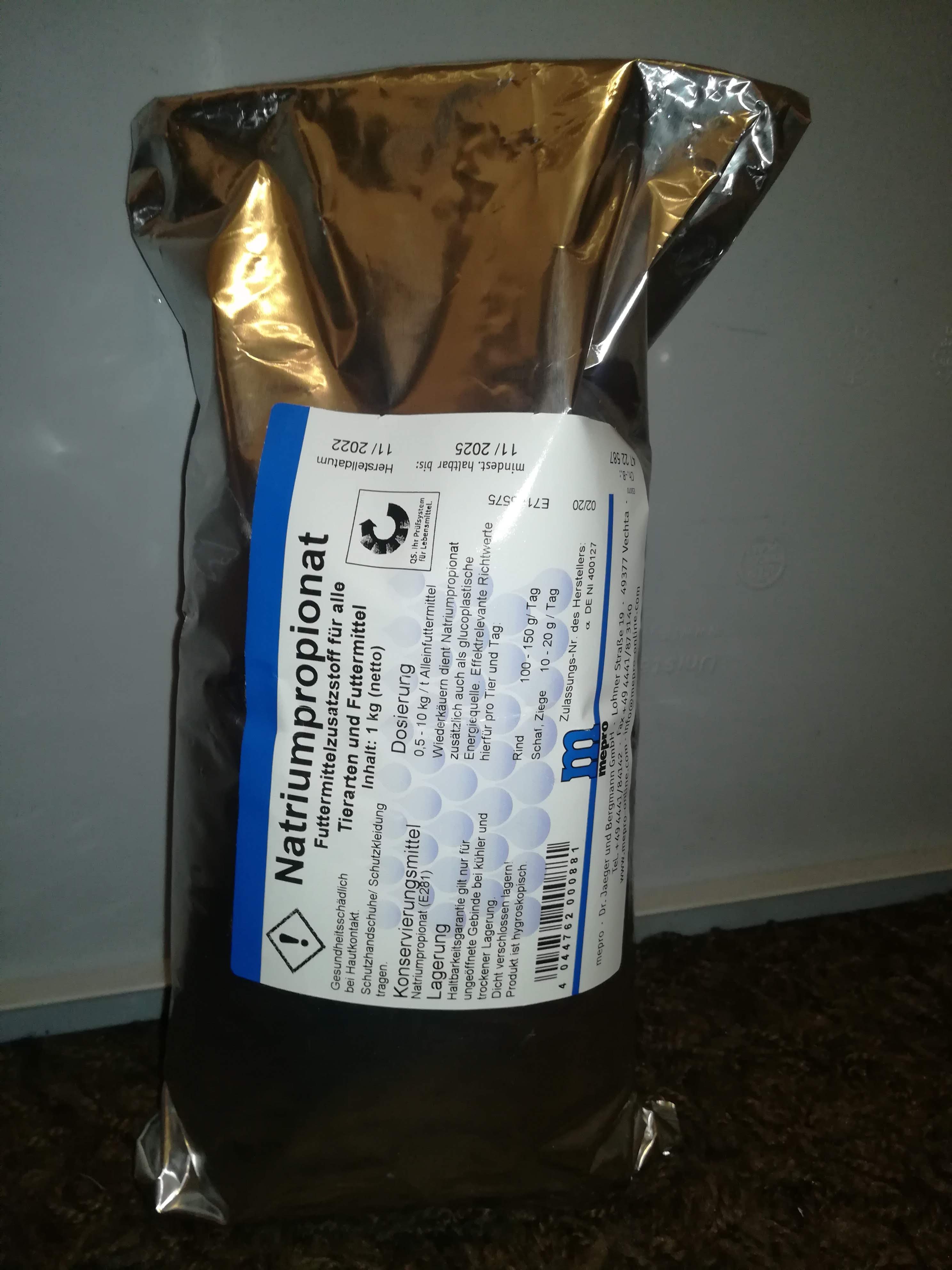
Sodium Propionate
First I tried using Sodium Propionate, which was able to increase the conductivity but added an unpleasant smell to the ink and was quite corrosive on the metal parts.
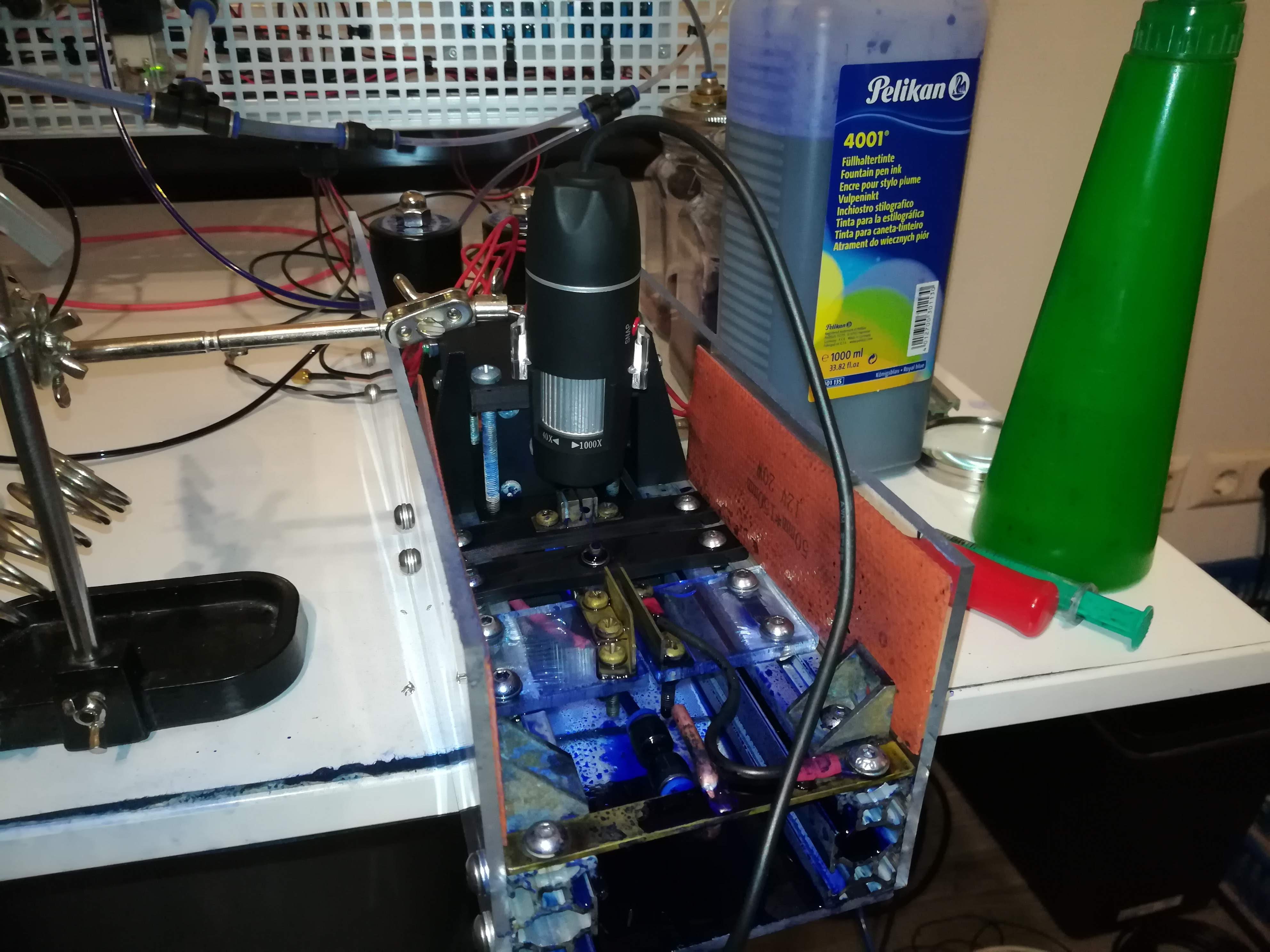
Measuring Conductivity with another PPM Sensor
I still used it for a decent amount of time.
Because of the corrosion on aluminum, copper, and brass parts that was caused by the sodium propionate and the former used additives, I replaced almost all feed lines and metal parts with either plastic or stainless steel at some point, to make the printer as corrosion resistant as possible.
Old Printhead with Signs of Corrosion on the Brass PartsNew Printhead made of Stainless Steel
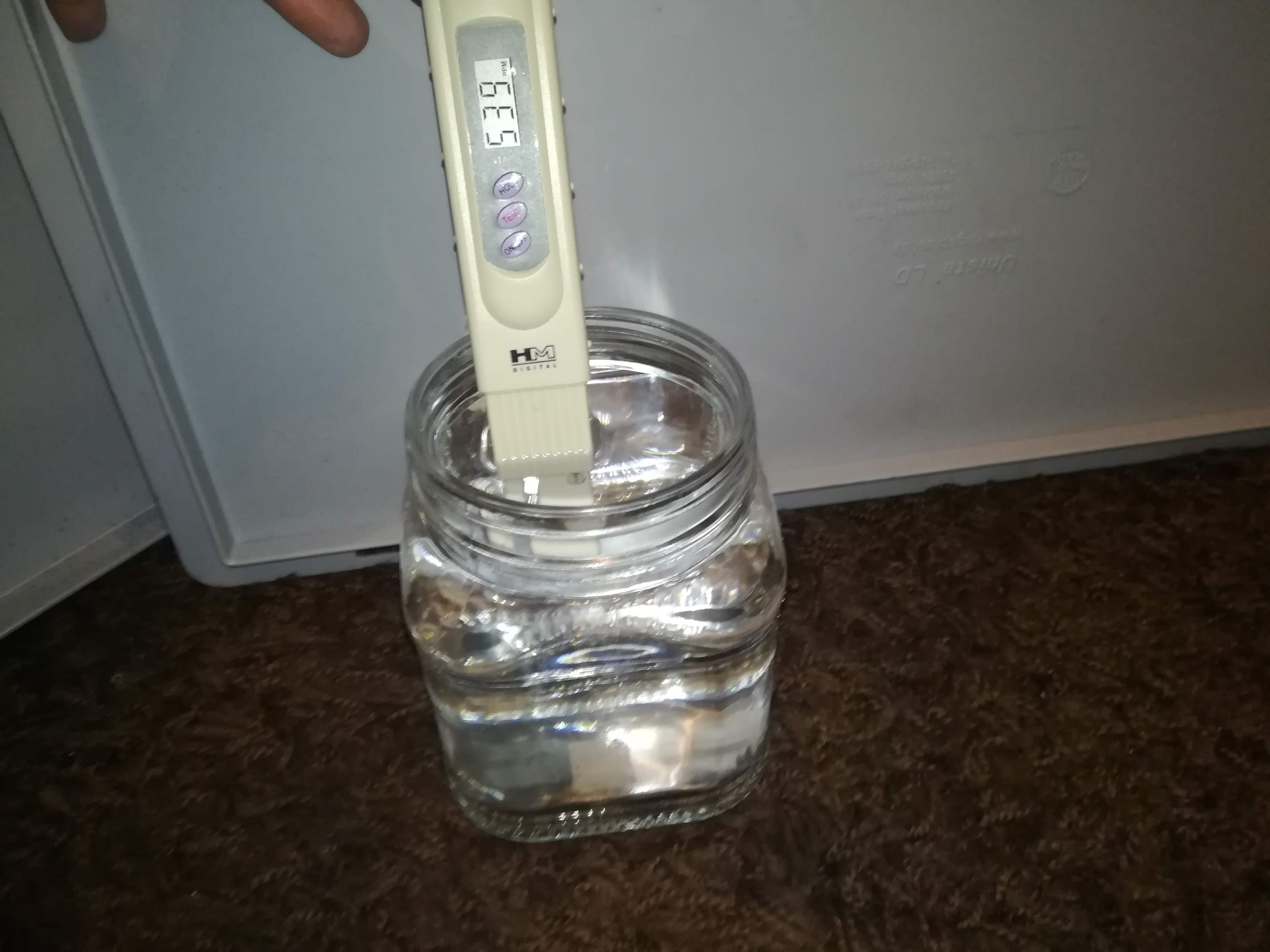
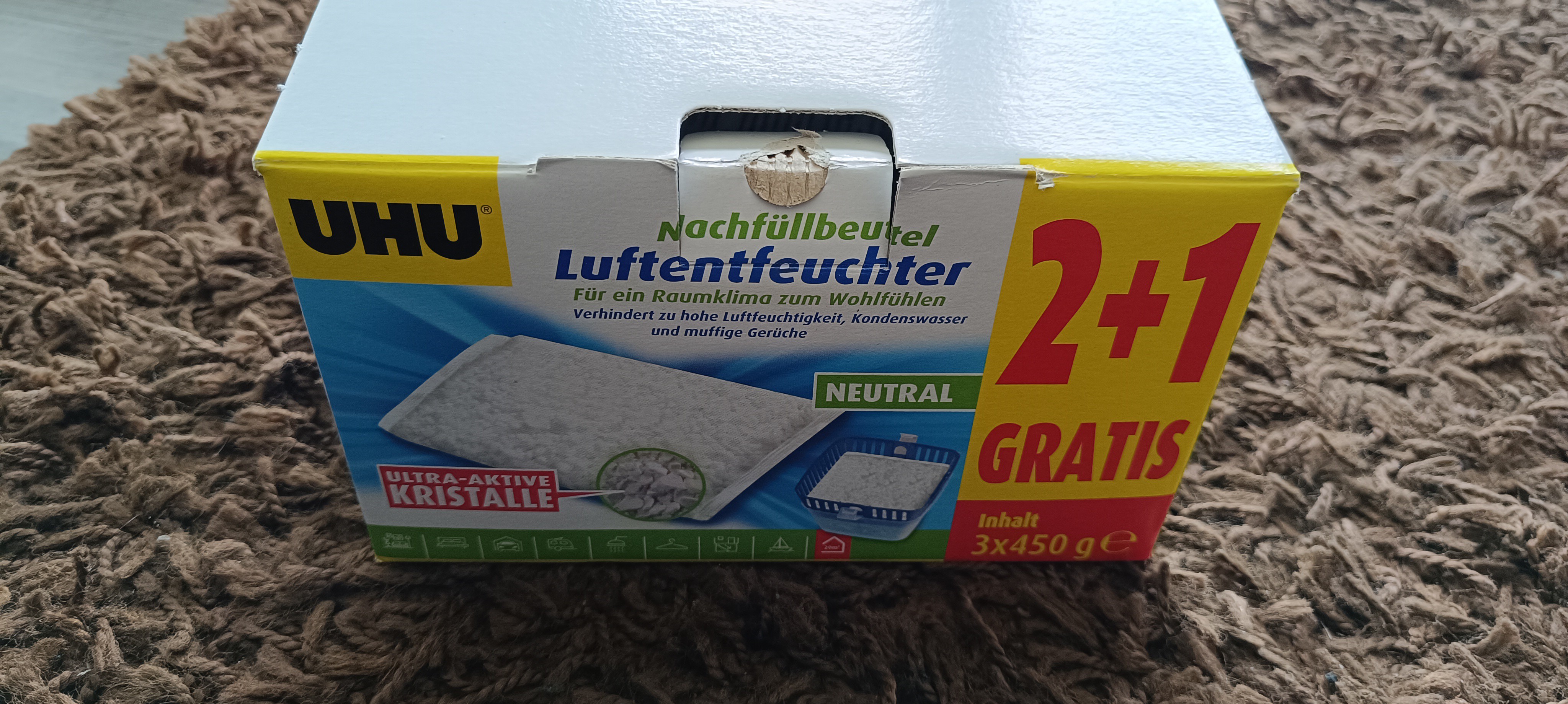
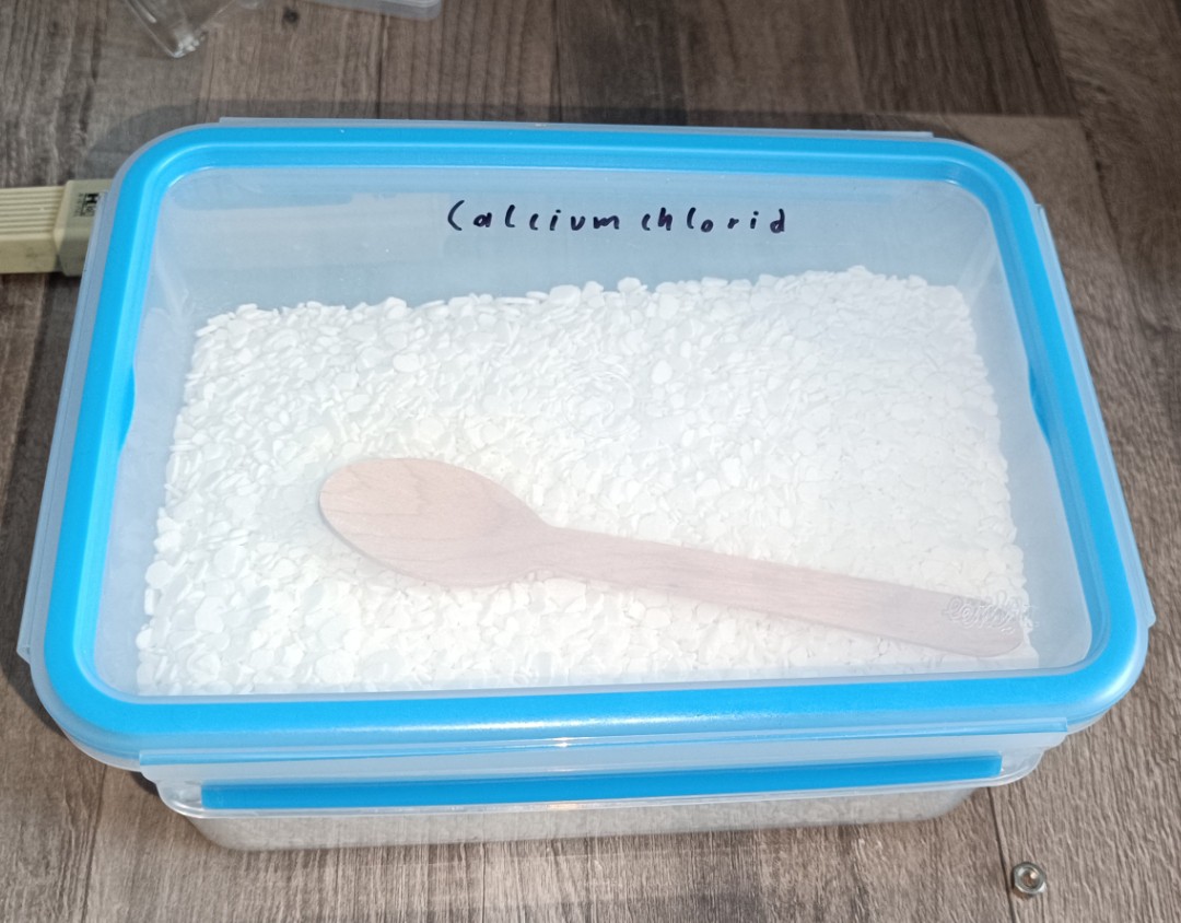
To get rid of the unpleasant smell and oily residue of the sodium propionate I searched for another ethanol dissolvable salt and found out that the Calcium Chloride from air dehumidifiers is also soluble in ethanol.
Air DehumidifierCalcium Chloride742ppmIt added a white Color to the Ink
The Sodium Chloride was good for increasing conductivity, but after working with it for a while I saw that it was also very corrosive on the brass, copper, and aluminum parts of the printhead that I could not replace with the last update.
Since it is used for dehumidifying, it is very hygroscopic and forms a closed layer with water underneath it wherever it gets spilled while testing. So it was very corrosive and was somehow dirt attracting with its wet and flaky appearance.
Rust on some of the Stainless Steel Parts, Printhead Bottom covered with Calcium Chloride Calcium Chloride Flakes on every Surface.
So another salt was needed.
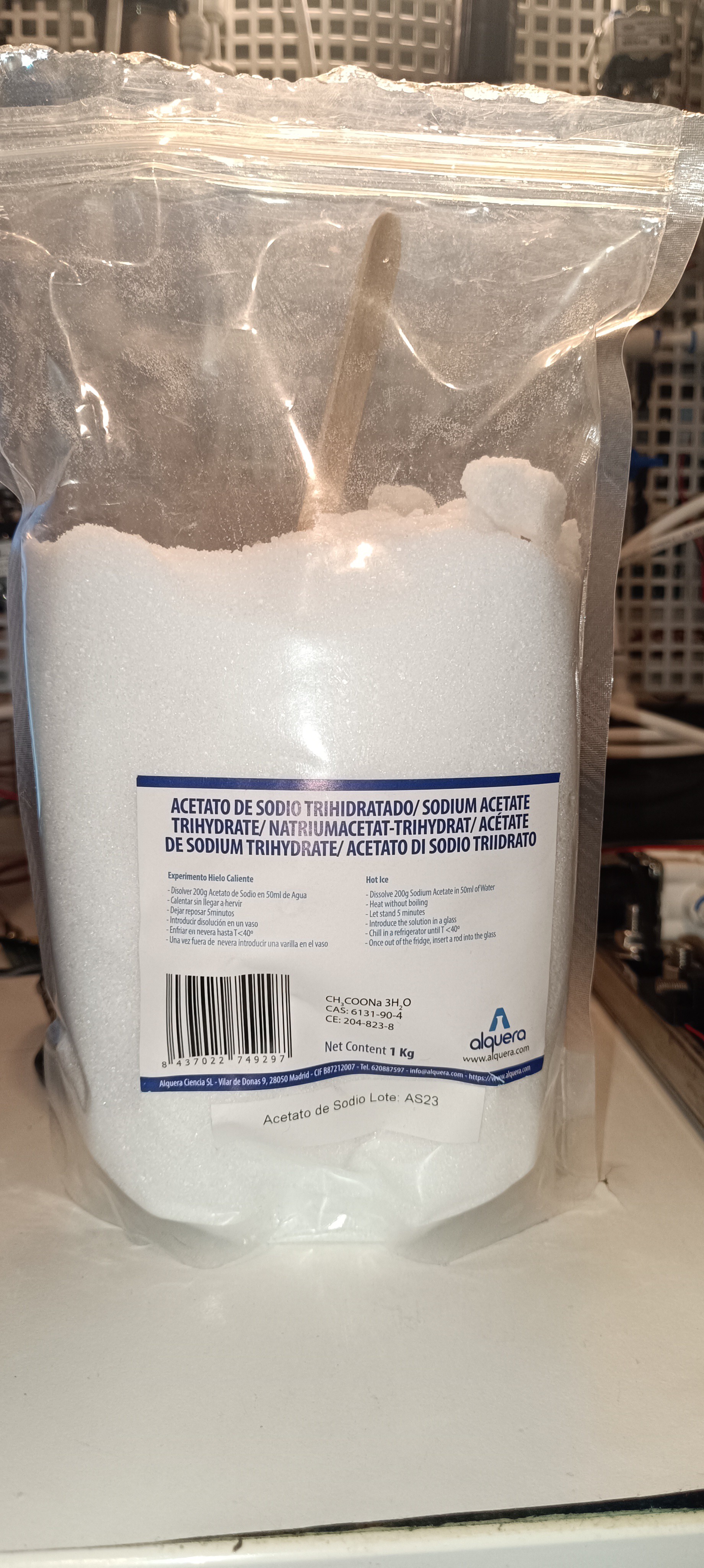
After some searching, I found out that Sodium Acetate is also soluble in ethanol so I ordered 1kg of it.
It turned out to be a lot less corrosive than all salts I tried before and it was well soluble in ethanol. The vinegar like smell is also minimal when mixed with ethanol.
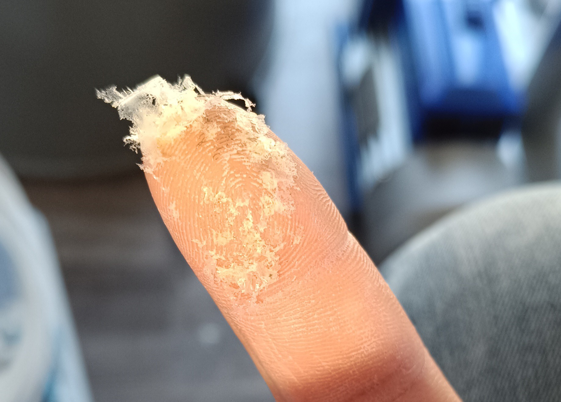
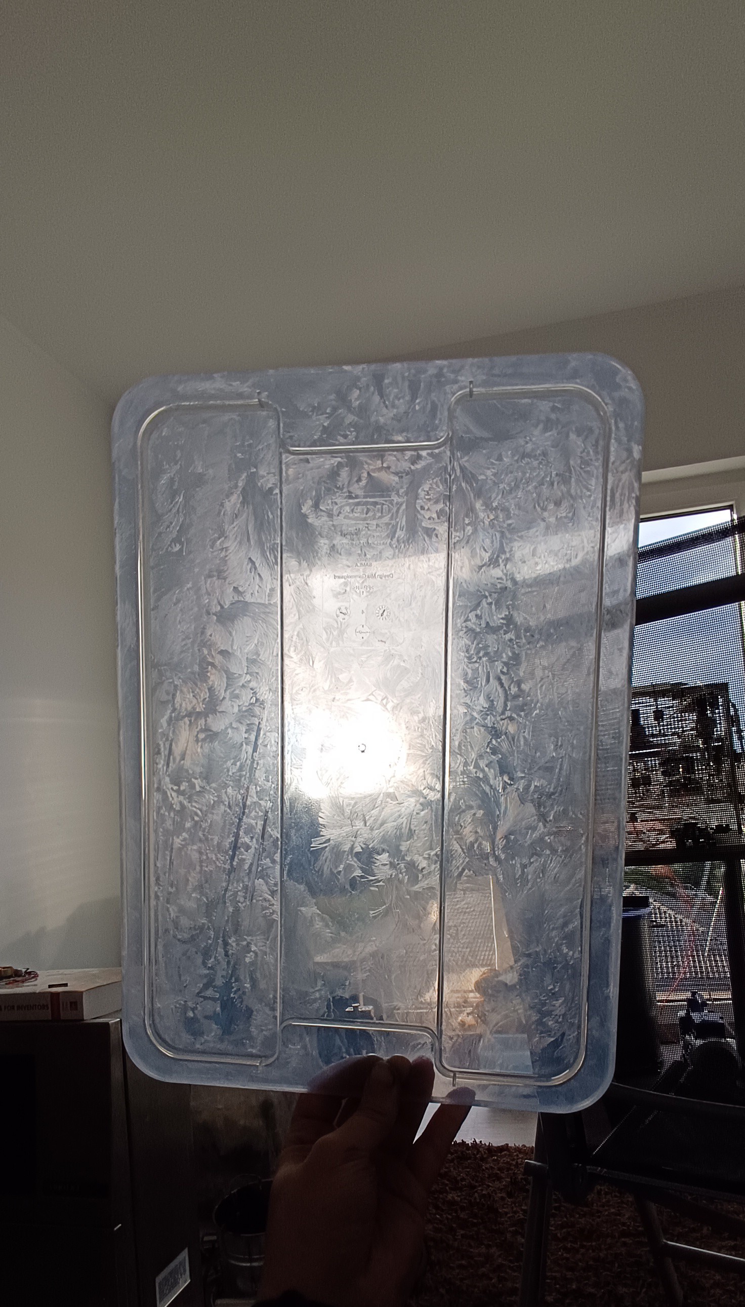
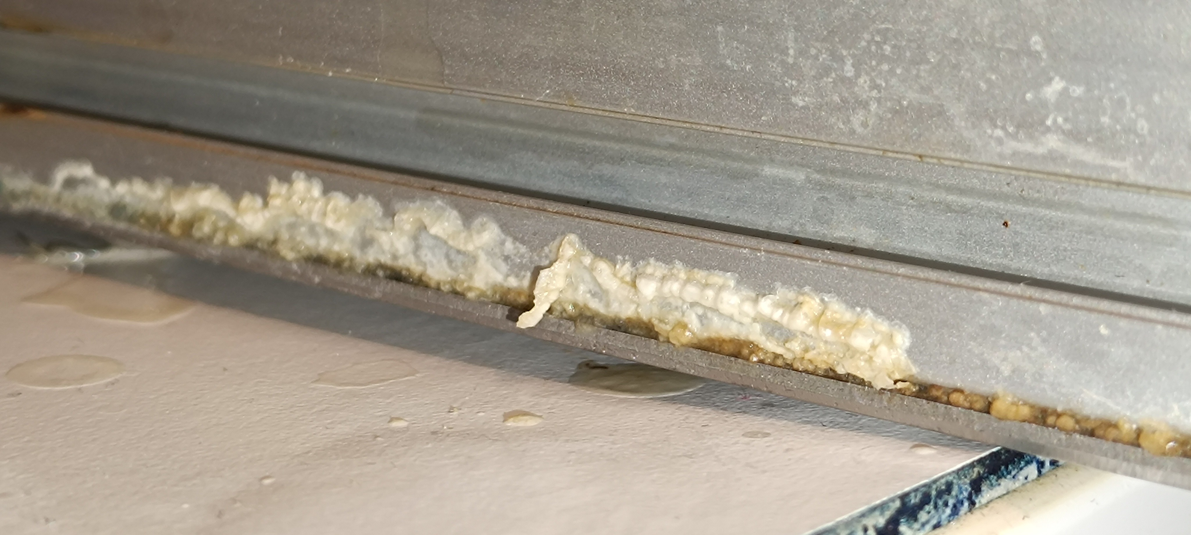
An important thing while working with it is that even though it dissolves very well, not that much of it dissolves in ethanol, and if the solution gets saturated, it tends to crystallize and settle on the bottom, which can cause problems at places that are not always filled with ink like vacuum lines and solenoid valves.
Sodium Acetate CrystalsSodium Acetate CrystalsA few Crystals on the grey Parts
In contrast to Calcium Chloride, it's easy to wash it away with ethanol or water to clean the printhead.
At the time I'm writing this, I'm still using the Sodium Acetate without any major problems.
For now, there are:
- The Temperature in ⁰C
- The Conductivity in ppm
- The Viscosity in seconds for draining
While the conductivity and temperature readings give you the current temperature in ⁰C and conductivity in ppm, the viscosity reading is just a number that equals an unknown viscosity without a calibration factor. It still shows a rise or fall of the counted time if the viscosity rises or falls and can be used to keep the viscosity steady.
After working for some time with this viscosity measuring method, I noticed that the time count varies if some dirt particle enters the nozzle without blocking the stream. When this happens the stream is still present, but the orifice size gets slightly reduced which leads to a longer drain time without a change in viscosity.
This measuring method would also no longer be possible if I would switch to a pump feed system instead of a pressurized air feed system, in the future, since this would no longer have a pressurized tank.
Because of these drawbacks, I replaced it with a falling ball viscosimeter which they also use in some commercial CIJ Printers.
Falling Ball Viscosimeter6mm Steel Ball
The falling ball viscosimeter works by lifting a steel ball in a fuild filled pipe and dropping it while counting the time it needs to fall.
I will write more about it in the next build log.
Polyvinylbutyral
For mixing a real ink, that can be used for printing, there needs to be something in it that remains when the ethanol evaporates. While the sodium acetate crystals also remain when the ethanol drys up, they do not stick to the surface very well and they would dissolve again if the surface gets wiped with water.
By adding polyvinylbutyral to the ethanol + sodium acetate mix, not only the viscosity can be modified to fit your needs, but the PVB also sticks nice to the surface and forms a smooth and water resistant coating.
So, it's possible to mix a clear ink from only these 3 ingredients, and by adding some pigments it would also be possible to mix a colored ink.
I think, with that, the ink should be ready for printing without further modifications and as soon as the printing process is working it could actually be used.
Over the last few days, I worked on a new printhead that is more resistant to corrosion than the last one.
Here, you can see the latest prototype which is specially designed for charge testing and has therefore no high voltage electrode and a too-wide gutter which will be replaced when the charging works reliably:
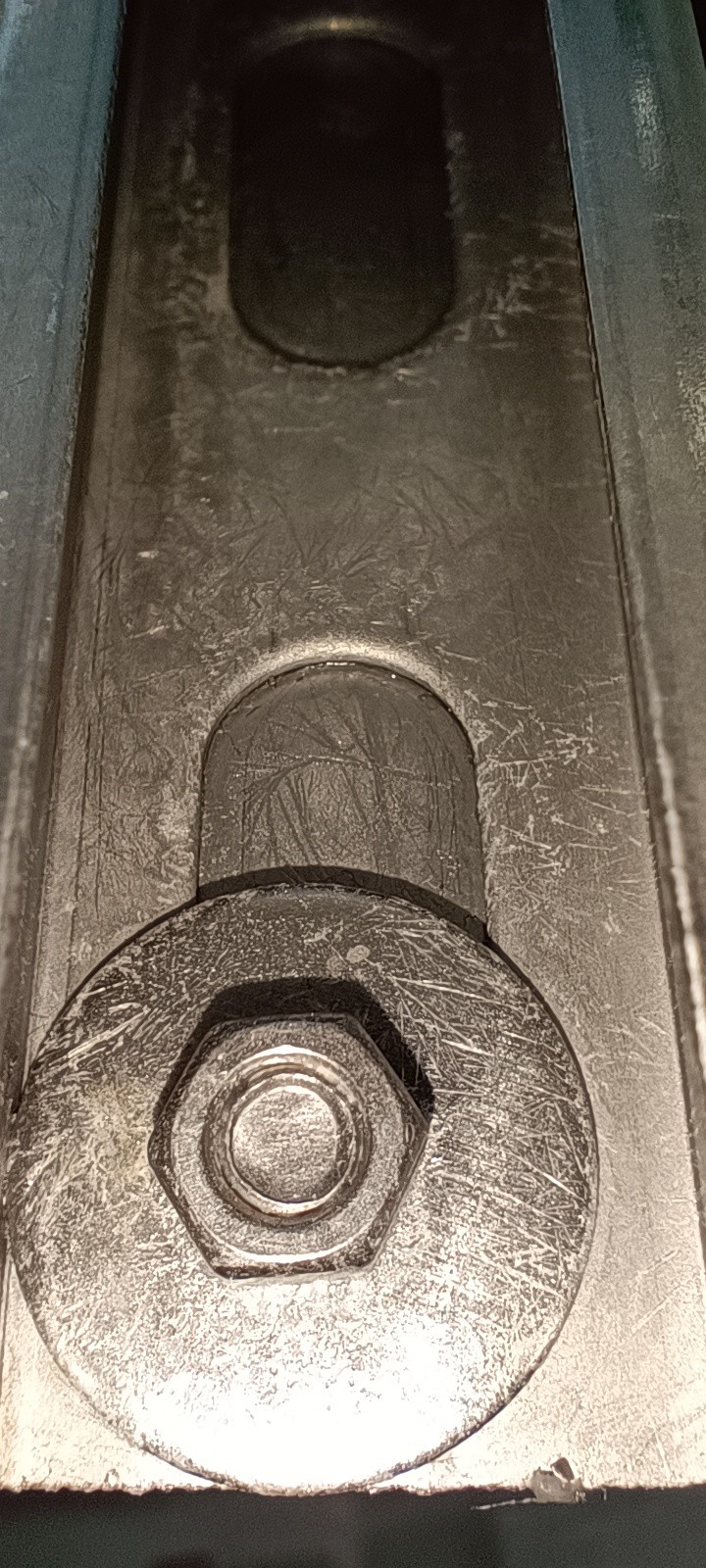
New Printhead with Stainless Steel Bottom and Mounting Rails
In addition to the stainless steel bottom, which I just took from the last printhead prototype, I also replaced the 2040 profiles with 26*18mm stainless steel mounting rails so that the printhead body (including screws and nuts) is now completely made out of stainless steel.
Starting from the back:
- The brass valves were replaced by the same valves as on the printer grid.
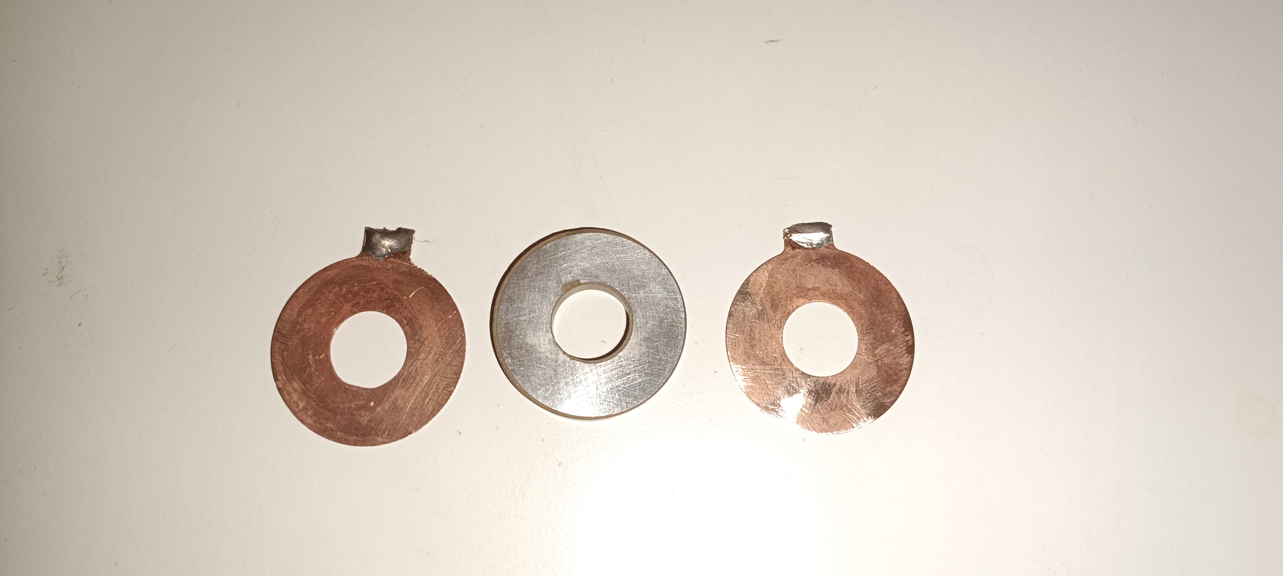
- The nozzle assembly is now made out of a plastic 1/4 inch fitting which can in contrast to a metal one come in contact with the "hot/powered" elements of the nozzle assembly, so no isolators are needed.
Piezo Ring and Contacting Plates
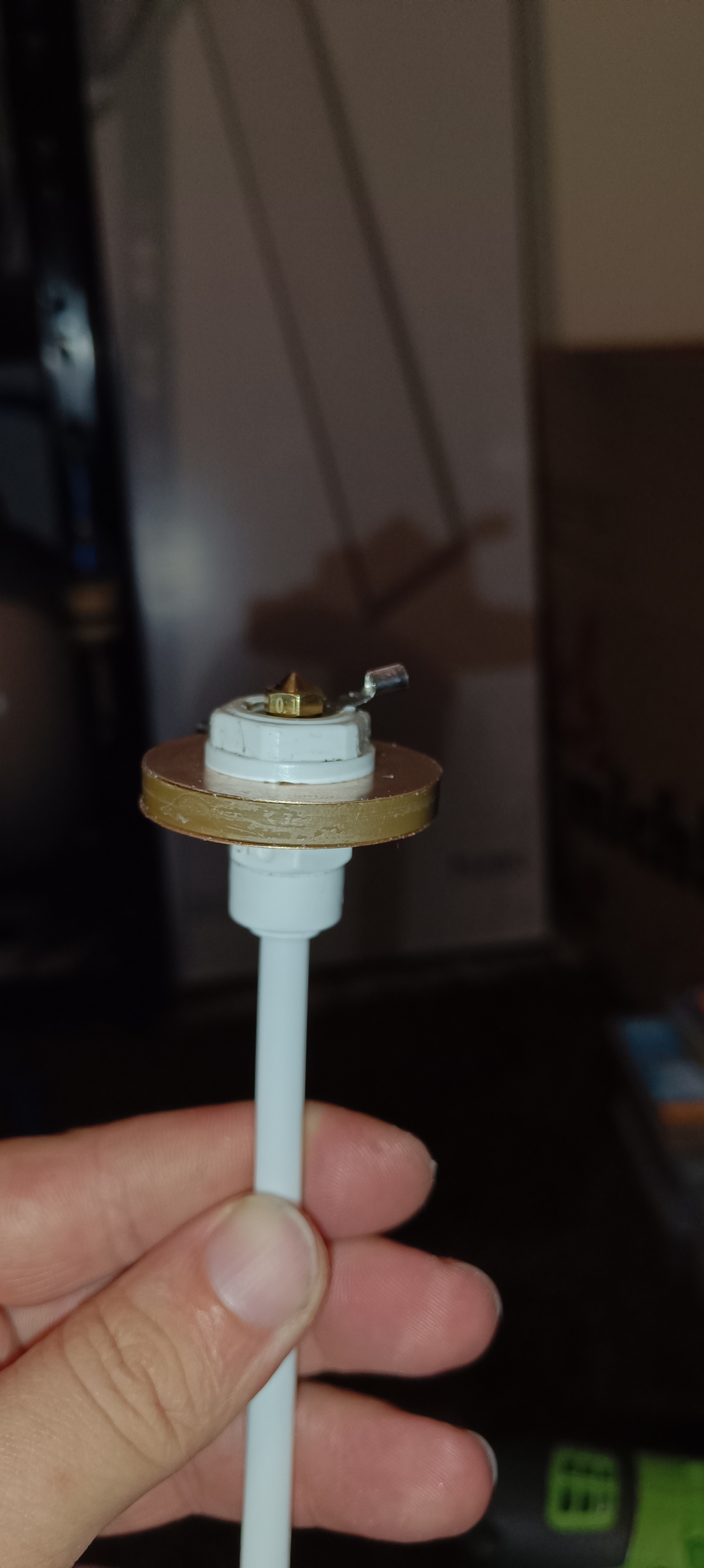
New minimalistic Nozzle Assembly
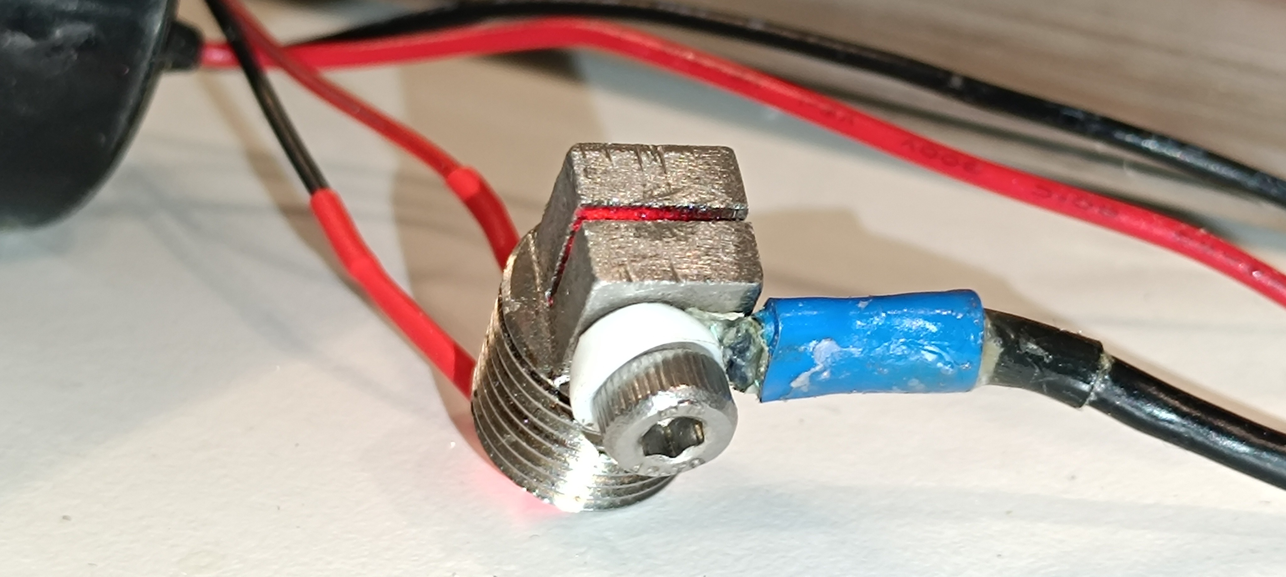
- The charge electrode is now made out of a stainless steel 1/4 inch fitting with a slit cut in it and a hole at the bottom for the strobe LED that illuminates the ink stream to make the breakup visible.
New Charge Electrode with LED
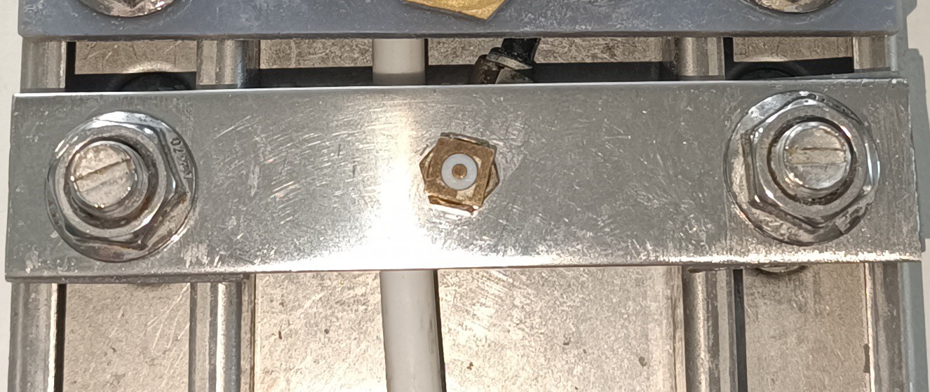
- The phase detector antenna/feedback sensor is now mounted onto a stainless steel bracket.
Phase Detection Antenna
- The high voltage electrode is currently missing.
- The Gutter is now made out of a 1/4-inch stainless steel fitting and a plastic elbow fitting mounted on a stainless steel bracket.
New Gutter
In addition to that I'm currently trying out Sodium Acetate as a "conductivity-increasing agent" which seems to be a lot less corrosive than the salts I tried before.
Sodium Acetate
With the new upgrades the printhead should no longer have the corrosion problems from before and is now ready for a new series of testing.
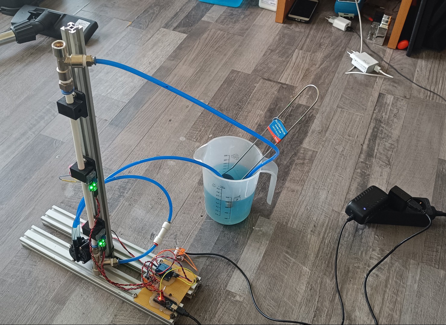
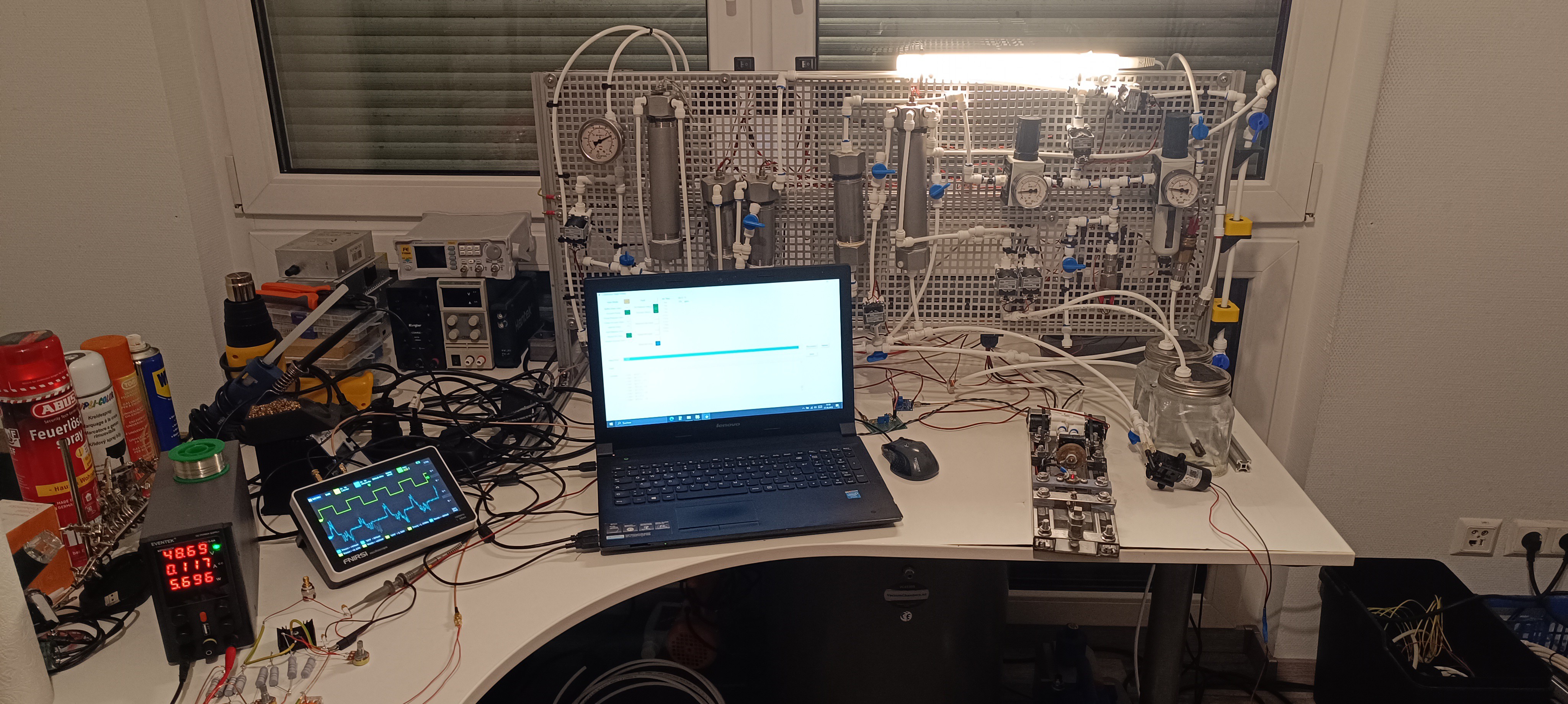
Here is an image of the whole setup:
The next update will be about the new viscosimeter which I'm currently working on.
Thank you very much for your interest in my projects :)
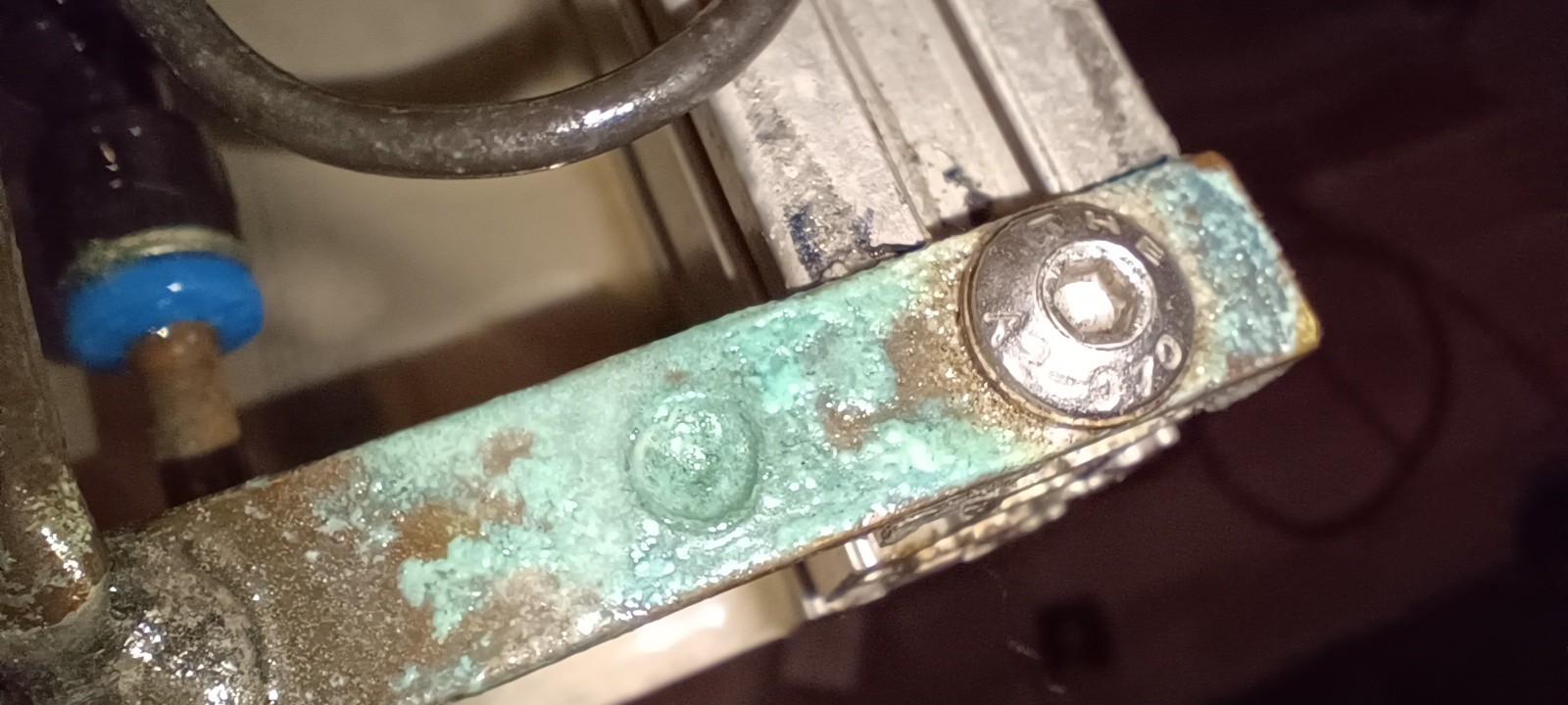
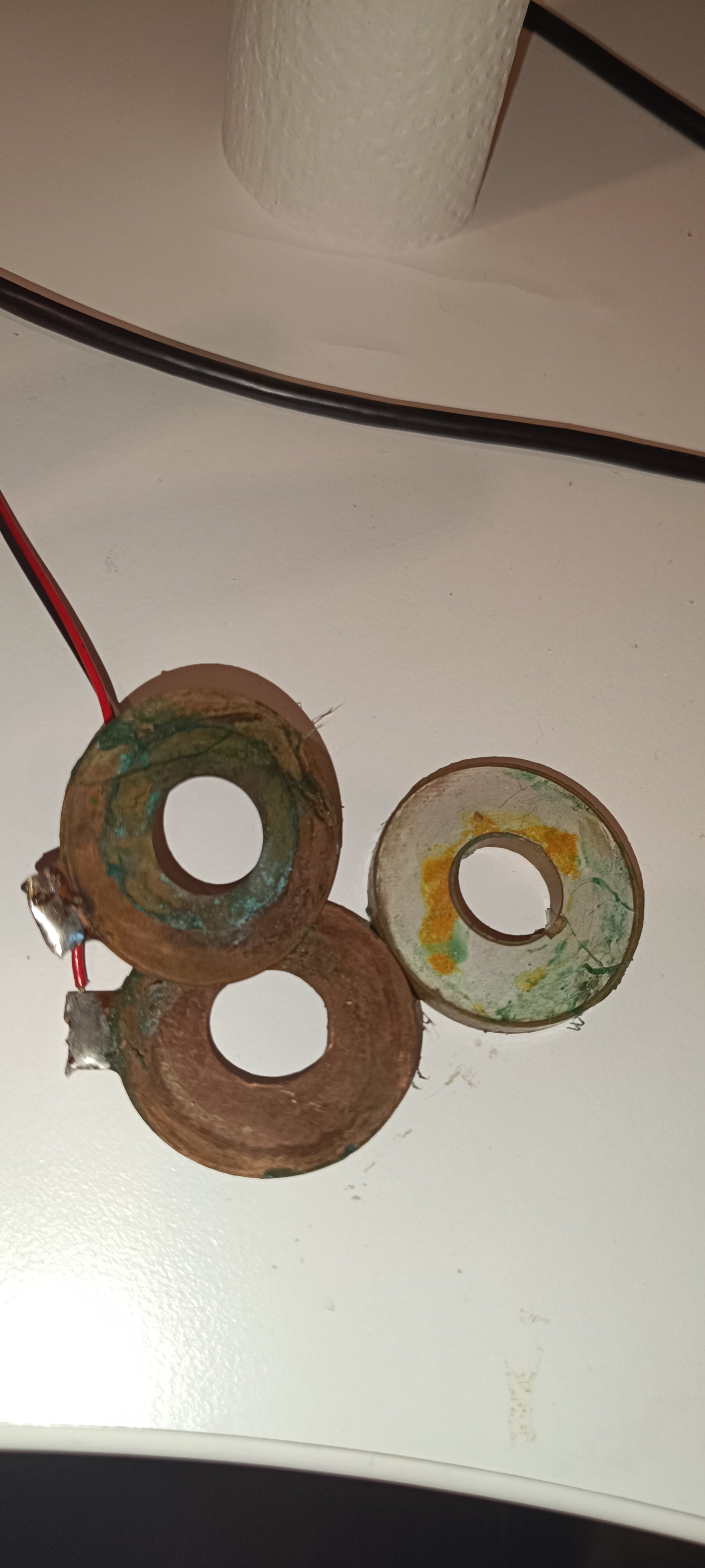
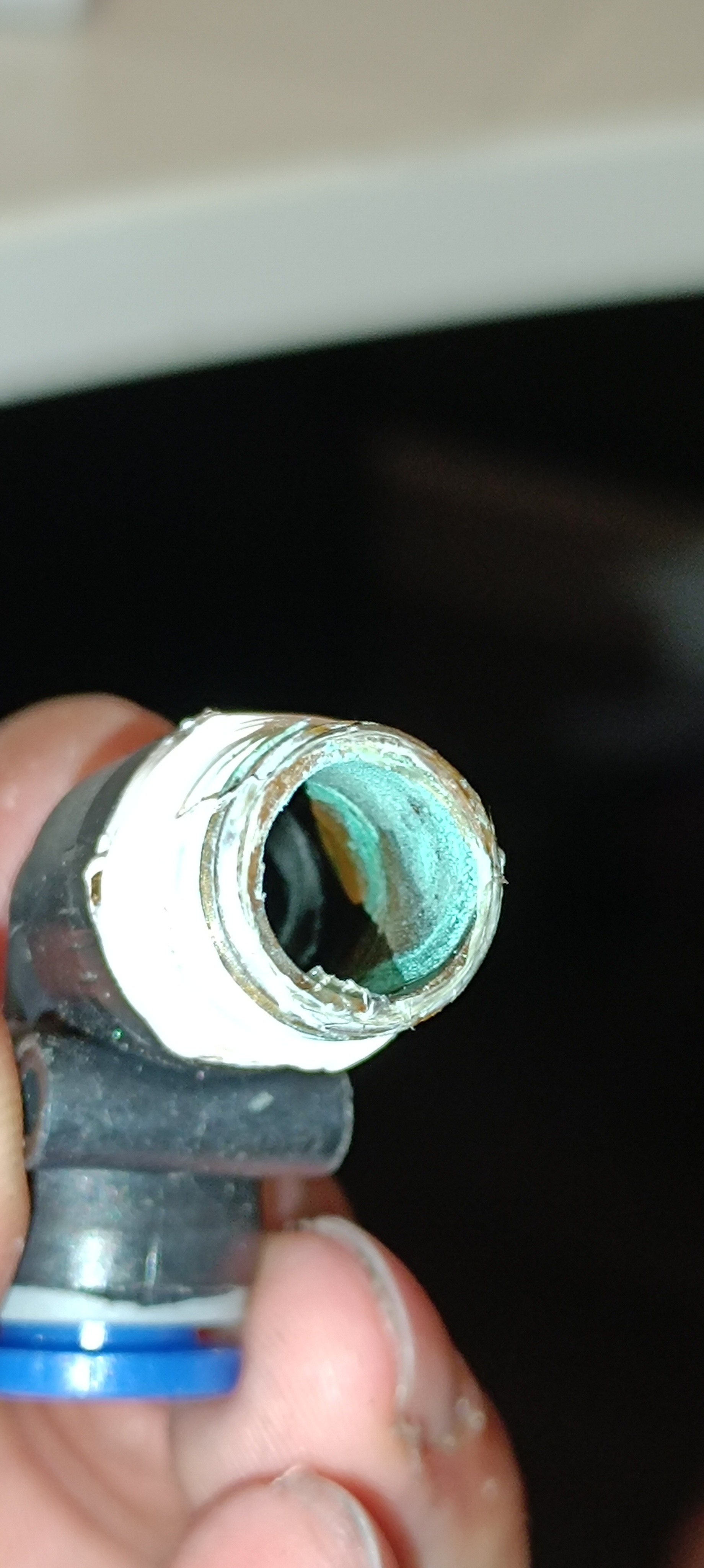
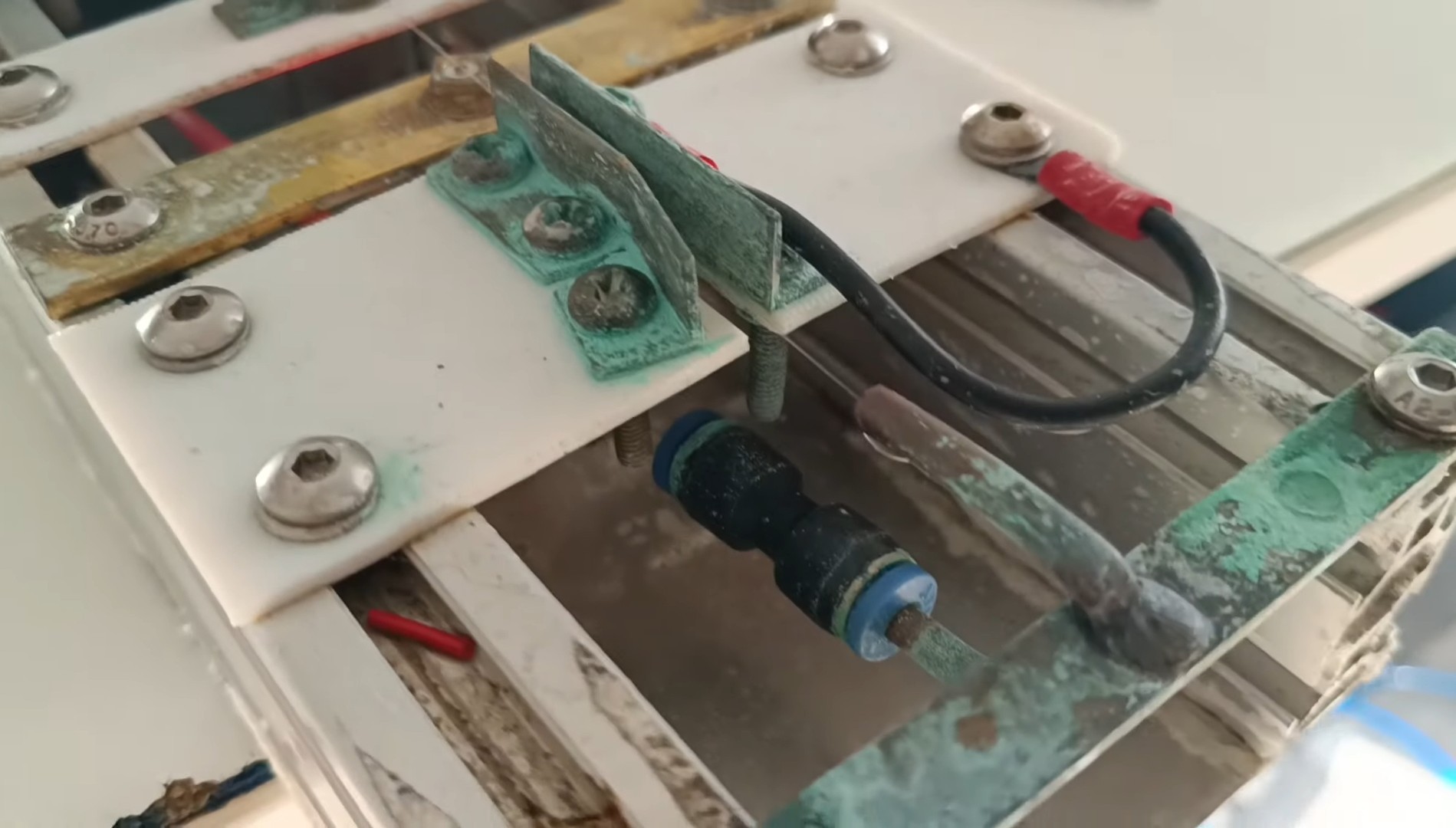
While testing I realized that the ink that I used caused a lot of corrosion on steel, copper, aluminum, and brass parts:
Corrosion on the Printhead
Corrosion on the Piezo Ring and Contact Plates
Salt Crystals on the Aluminum Profile
Corrosion inside a Fitting
Corrosion on the Charge Electrode, Deflection Plate, and Gutter
I assume this is caused by the sodium propionate that I used for increasing the conductivity of the ink.
Since the ink has to be conductive for the CIJ printing process, it needs to contain something that makes it this way and since all salts that I know so far can cause corrosion on metals like steel, copper, aluminum, and brass, these materials have to be replaced by other corrosion resistant materials like stainless steel, rubber, and plastic to prevent corrosion of the printer and also contamination of the ink.
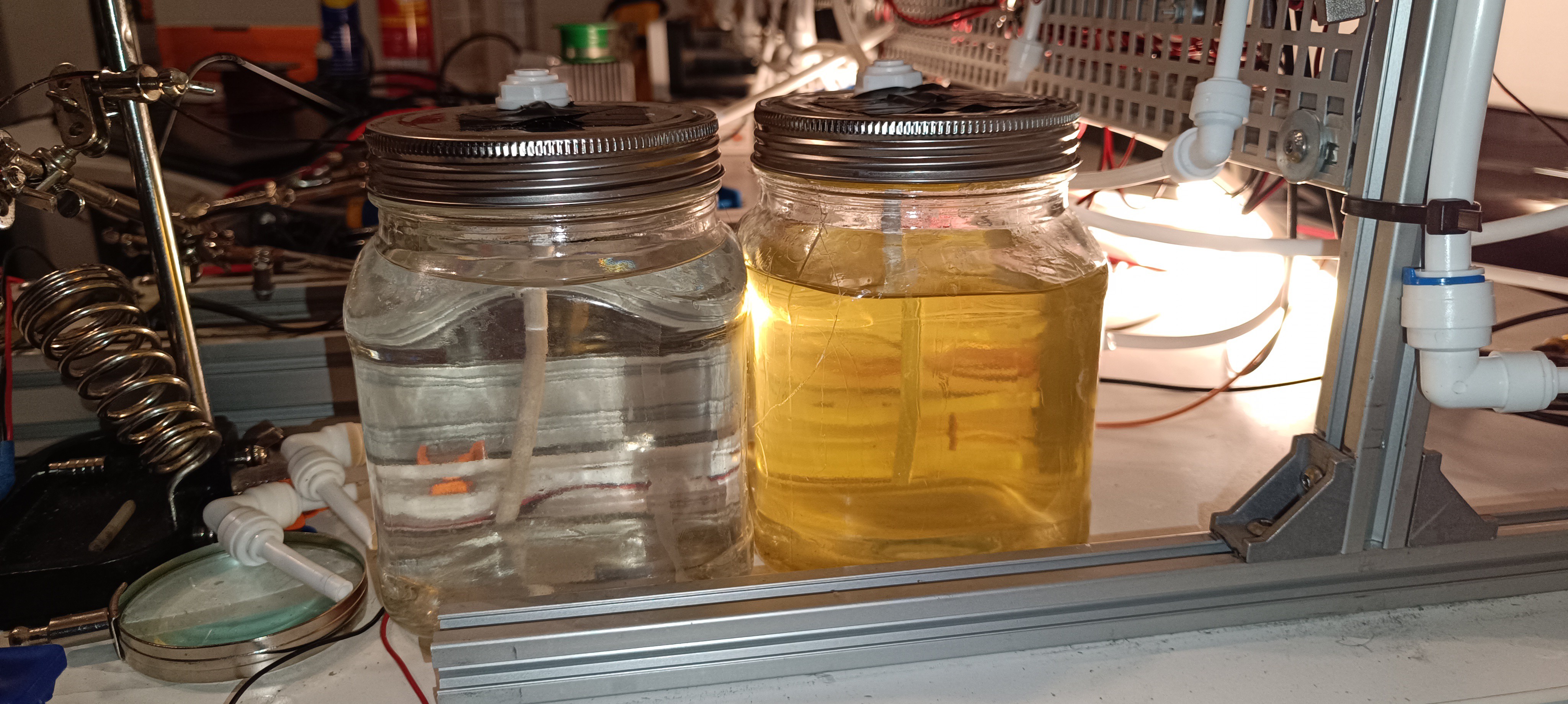
Fresh Ink on the left, Used Ink on the right
So, I searched for corrosion-resistant fittings to replace all the brass fittings and ultimately stumbled across the Reverse Osmosis plumbing system of white fittings of all sorts + white 1/4 inch and 3/8 inch PE tubing.
Old Setup at the bottom, New Setup at the top
Top Cap of the Vacuum Tank made out of Stainless Steel with Plastic FittingsVacuum Buffer/Overflow Tank, Valves for Draining the Tank, Ink Pressure Regulator in grey, Stainless Steel Vacuum Pump Exhaust Suppressor, Ink FilterFrom left to right: Ink Pressure Tank, Ink Pump Tank, Ink Pressure Overflow Tank + New Plastic Check Valves and Solenoid ValvesVacuum TankValves for Ink and MakeUp at the bottom, Valves for Pump Pressure and Venting at the top, Ink Pressure Regulator on the left, and Pump Pressure Regulator on the rightBesides the Pressure Regulators/Gauges and Vacuum/Pressure Switches, all Parts were replaced by either Stainless Steel or Plastic on the Printer
I think with all brass parts replaced by plastic or stainless steel the printer should now no longer have problems with corrosion caused by a small amount of salt in the ink.
While the printer hydraulics should be fine now, the printhead is still made out of brass, copper, and aluminum and will also need an upgrade to withstand corrosion.
I'm currently working on the feedback signal of the phase detection feature. This signal gets read from the ink droplets which get charged by the phase detection signal.
It took me multiple months until I was able to read anything from the ink droplets. My problem was that I couldn't find anything similar to the "reading of charge on small fast flying droplets".
I read in multiple papers that they used a lock-in amplifier for reading the droplet's charge, which is a pretty expensive instrument that can filter very small signals out of the surrounding ambient noise, by searching for it with the help of a reference signal with the same frequency.
Unfortunately, such an instrument would cost more than all other parts of the project and there also was no IC or ready-to-use module with similar capabilities (besides one from China with a long shipping time).
Another time where @Paulo Campos helped me by giving me the circuit of a CIJ printer's phase detection amplifier.
Thanks a lot, my friend :)
It turned out that the circuit only contained a TL072 Opamp as an amplifier and some filtering - so no lock-in amplifier was needed.
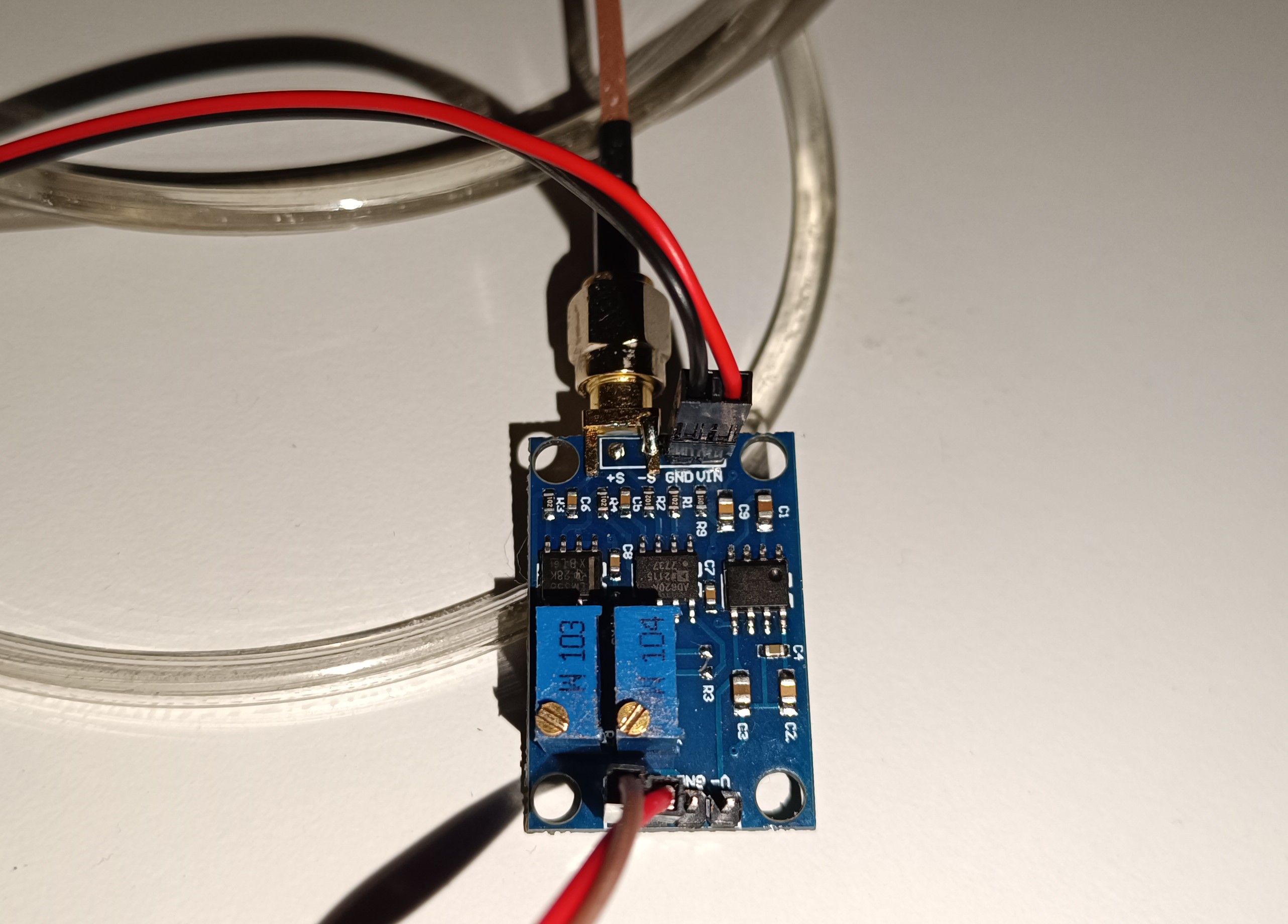
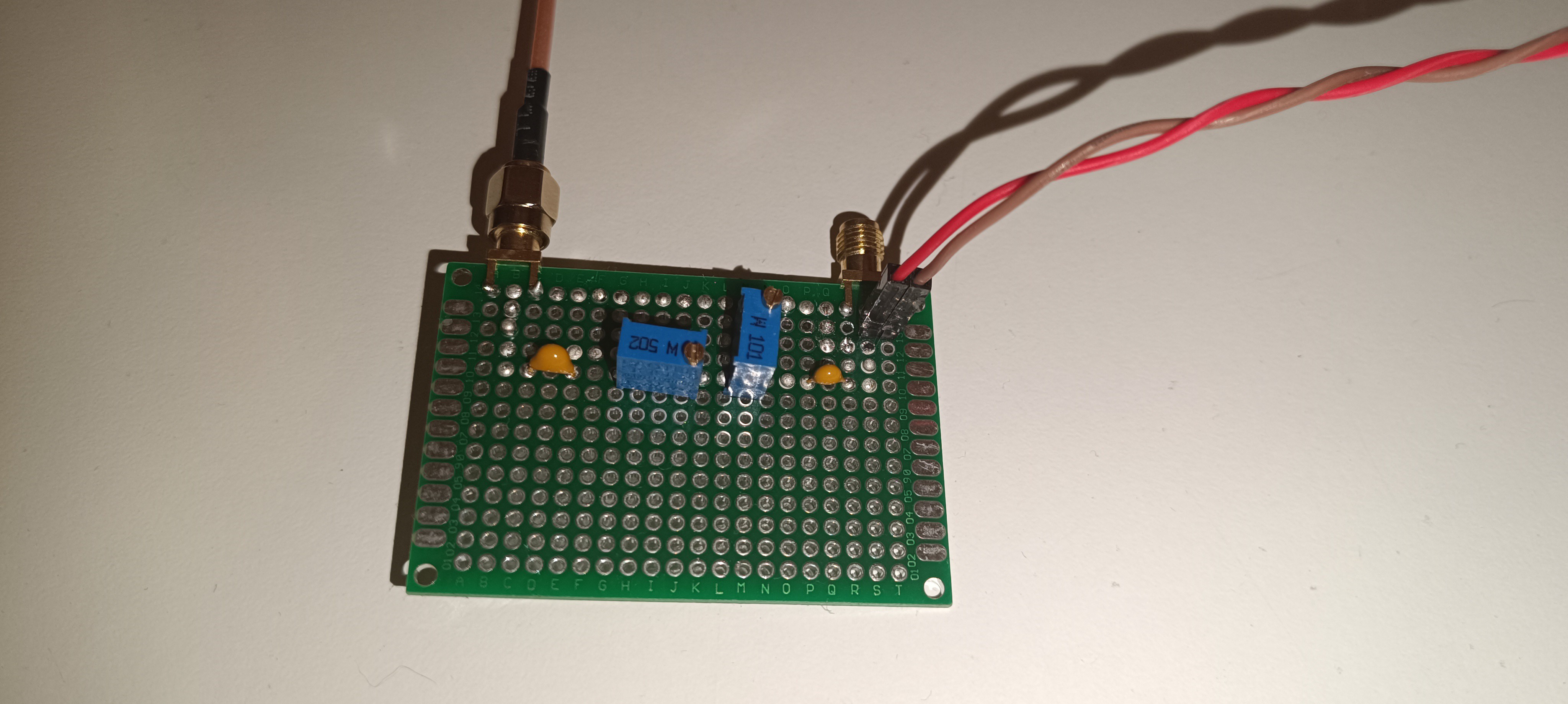
After building and testing the circuit 1:1 which didn't work with my DIY printer, I tried using an "AD620 small signal amplifier module" in combination with a self-built bandpass filter designed for 50kHz, which finally gave me a signal.
AD620 Small Signal Amplifier
50kHz Bandpass Filter
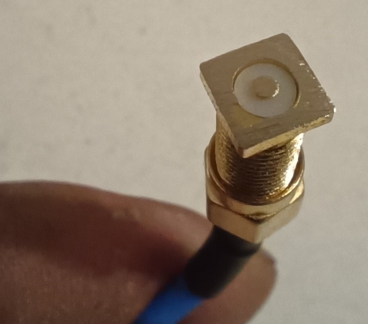
For the sensor or probe for reading the signal, I used a long SMA solder connector, from which I cut off and sanded down the legs to get a flat surface with the shielding on the outside and the probe pin in the middle. For the sensor, shielding is very important, because the signal that gets read from the droplets is smaller than the ambient noise and also smaller than the phase detection signal itself, which gets radiated out from the charge electrode.
Without good shielding, the sensor would pick up the signal from the charge electrode instead of the signal from the droplets.
Sanded down SMA solder connector as Sensor/Probe
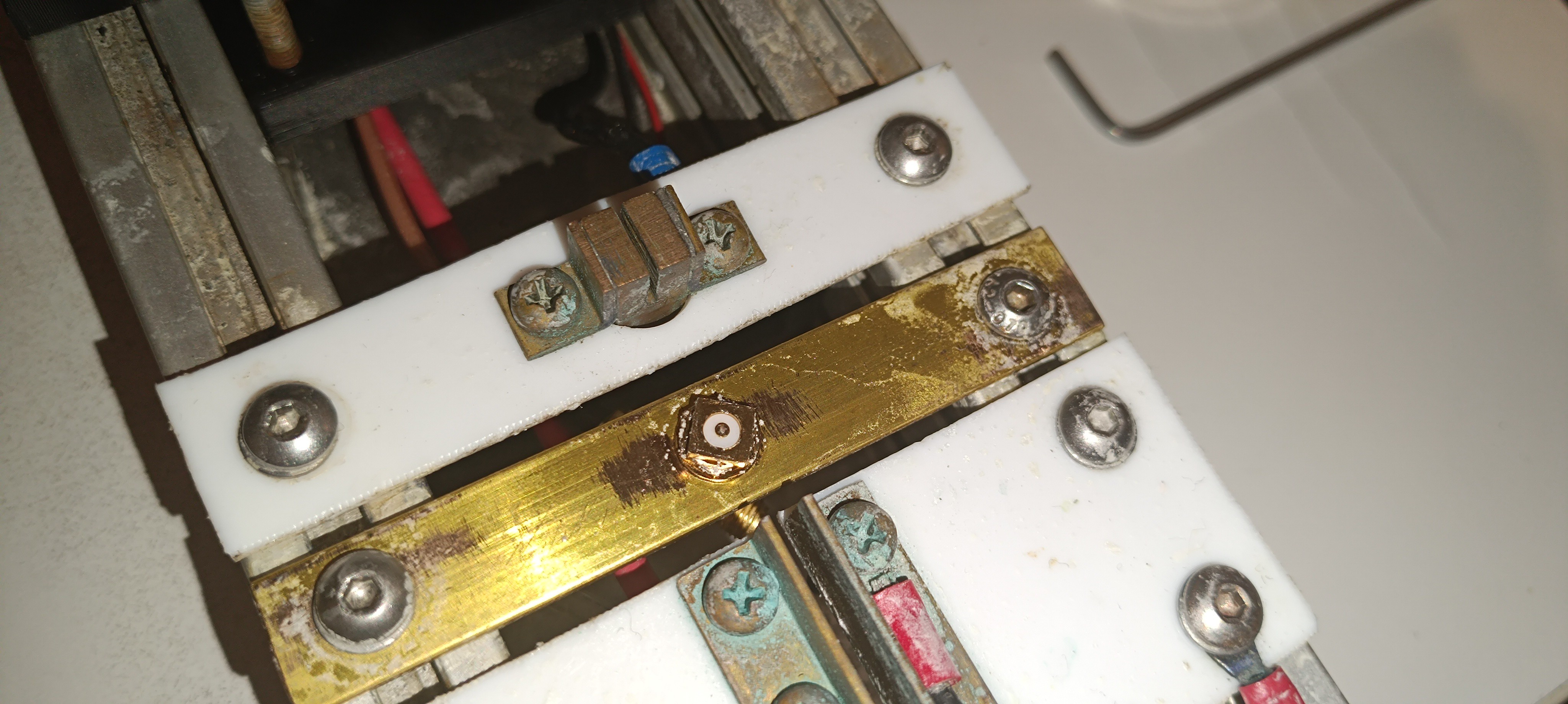
Phase Detection Sensor on the Printhead
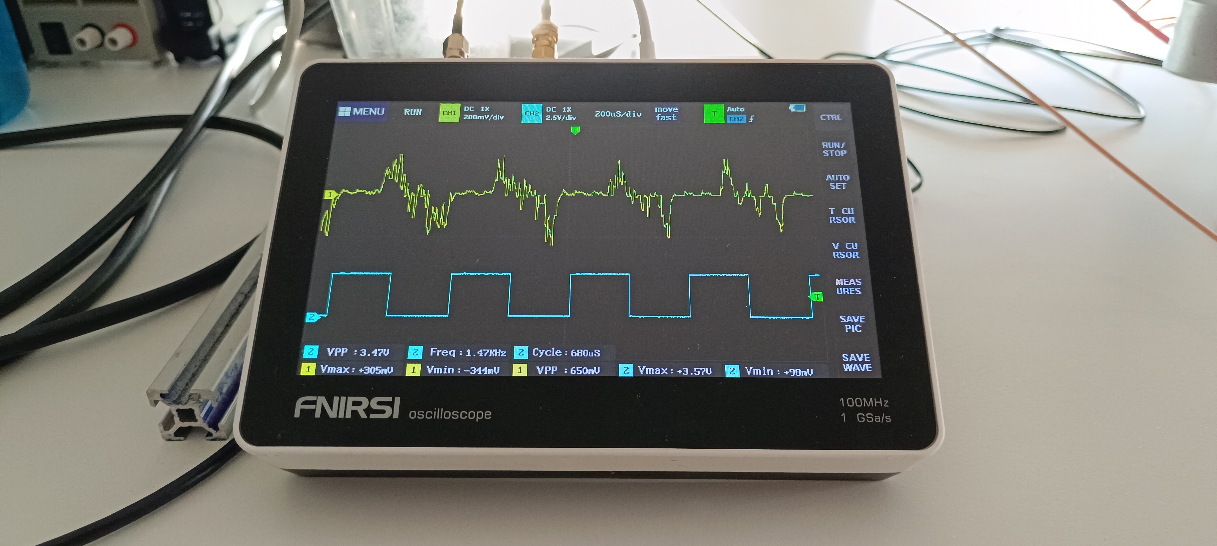
With the new setup, I could finally get some signal that reacts to the presence of the ink droplets.
Trigger Signal in blue, Feedback Signal in yellow
When I stopped the ink stream by blocking the nozzle with my finger, the signal disappeared and when I turned off the piezo, the signal got replaced by noise. The amplitude of the signal got decreased when the ink droplets passed the sensor at a higher distance and got increased when the ink droplets passed the sensor at a lower distance.
So, it should be the signal I'm looking for since November last year :)
But the signal is not perfect, yet. Normally the phase detection feedback signal has the shape of a hedgehog with the highest voltages in the middle and the lowest voltages on the outside. It shouldn't go negative either and it should also be more stable.
So, there will be some improvement needed until it can be used for selecting the right phase based on it.
However, having this signal gives me something to look at while adjusting things on the printer and doing improvements. I can change something and look at how it affects the signal which gives me a way of feedback that I never had before.
Here are some videos about ink stream detection testing based on the feedback signal:
It's nice to have something to show about this project, again.
Here is another test:
This time with 48V instead of 24V piezo drive voltage. In the video you can see that by adjusting the drive voltage the feedback signal also changes.
Thank you very much for your interest in my project :)
 Dominik Meffert