 Michael Gardi
Overview
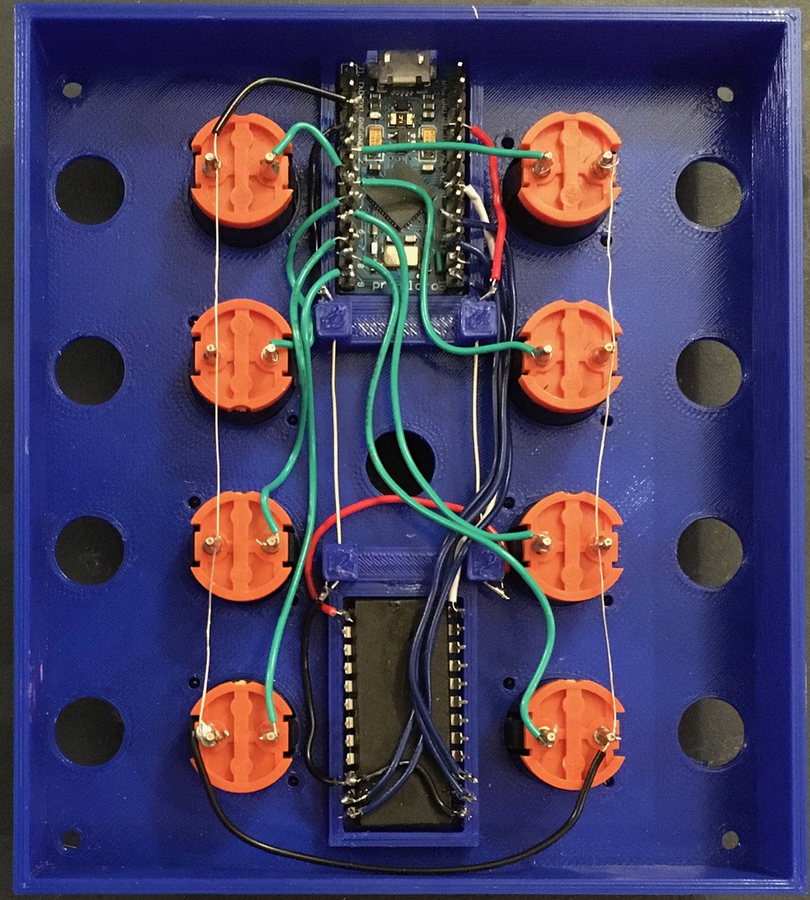
Macropad 2 is just going to be a remix of A Tile Based MacroPad with the same parts rearranged a little bit, so hopefully there will be no surprises.
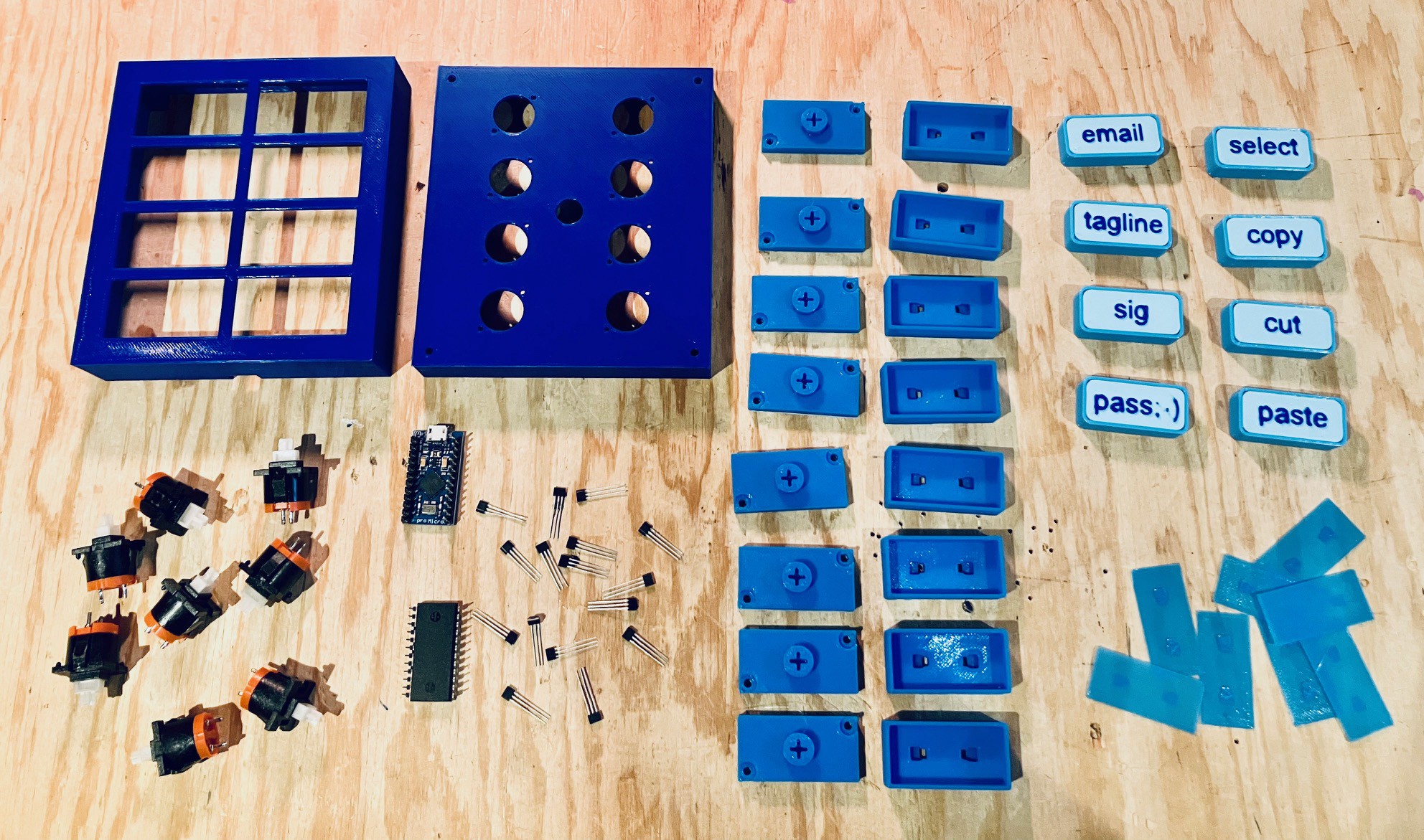
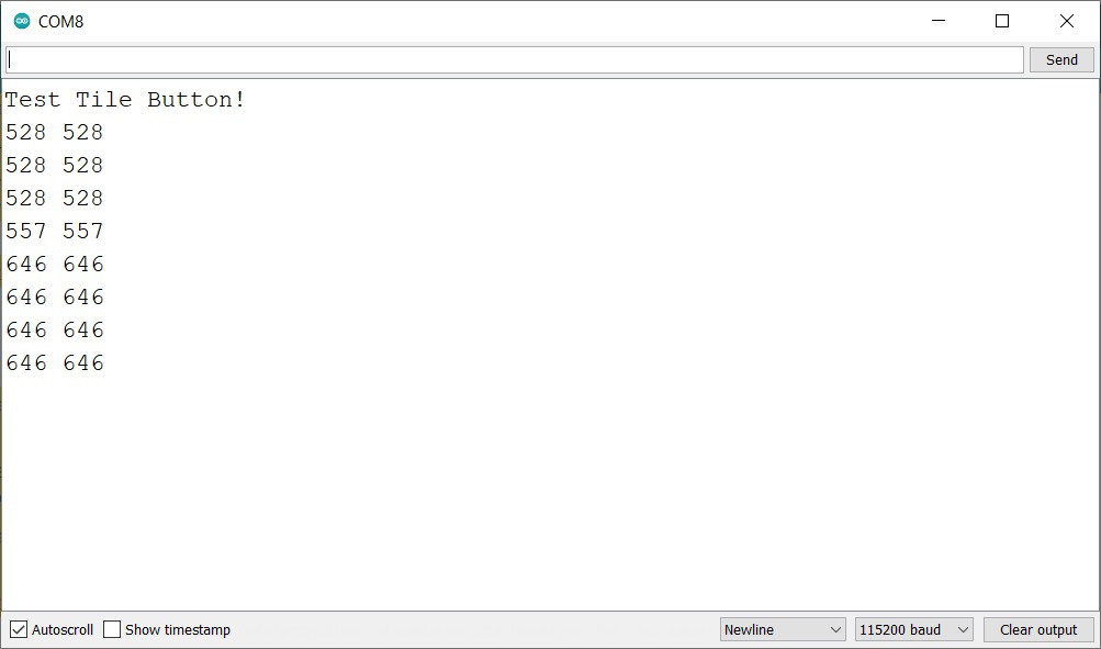
In fact the sketch used for that project should run with few if any changes on this new one. Of course new project means new color scheme.
Segway
This is where all the work happened creating a MacroPad 2. If you are interested in the details of how this happened I would strongly encourage you to have a look at this project's logs for the complete picture. Here is a handy link: Project Logs. Make sure that the SORT BY: is set to Oldest to get a chronological view.
Final Thoughts
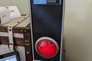
Well I have two beautiful (IMHO) MacroPads now. They both work well (even together).
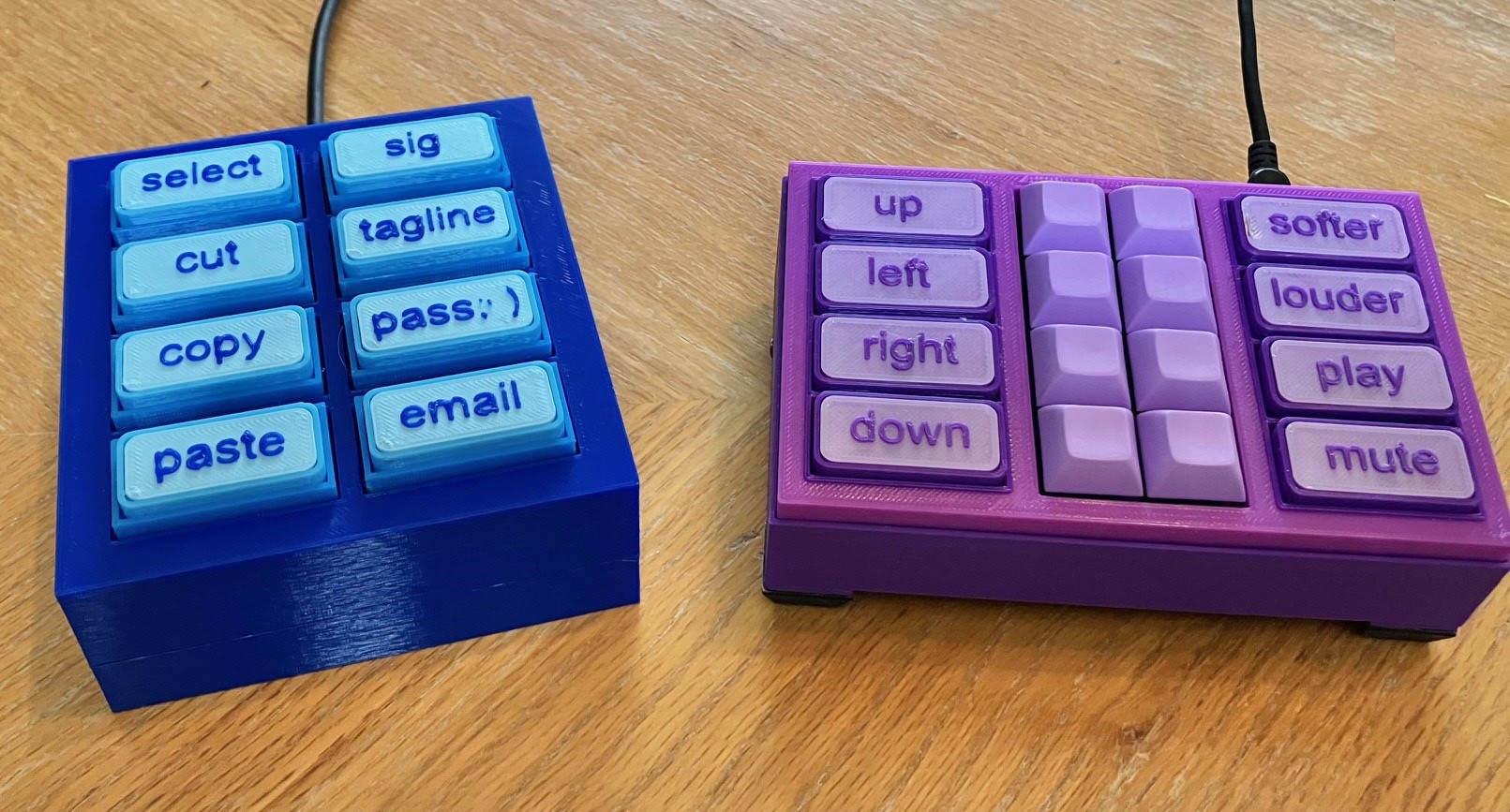
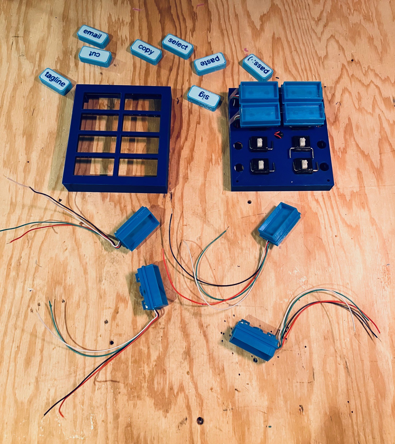
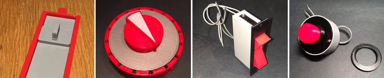
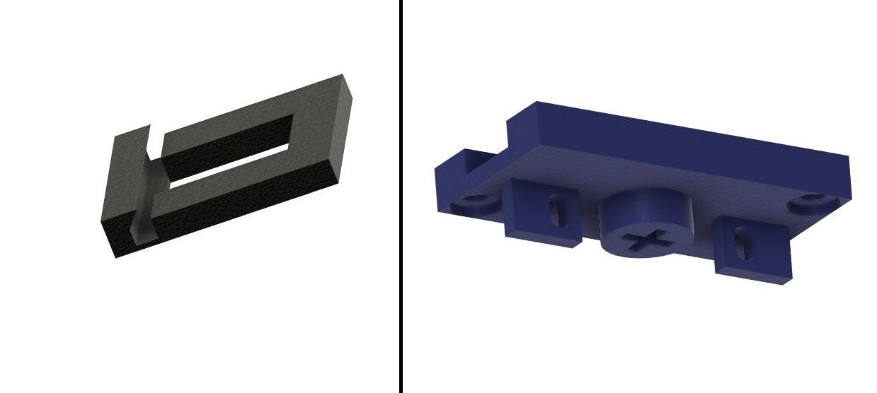
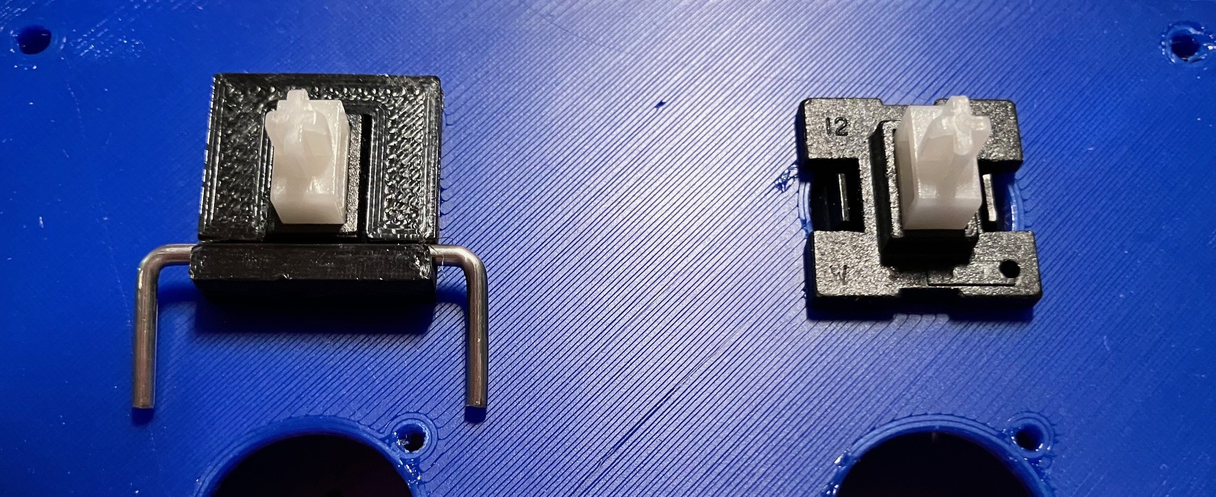
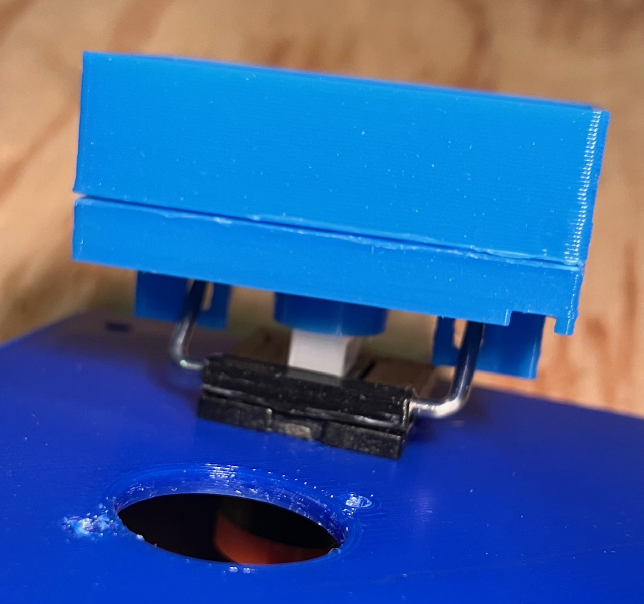
I started the second "Tile Holder Button" version because I had found myself pressing the tiles on the "Keycap Button" version instead of the keys by mistake. It turned out that making Tile Holder Buttons and more importantly getting the "feel" of the button presses right was a bit of a challenge (see the logs for details), but in the end I'm happy with the way they work now.
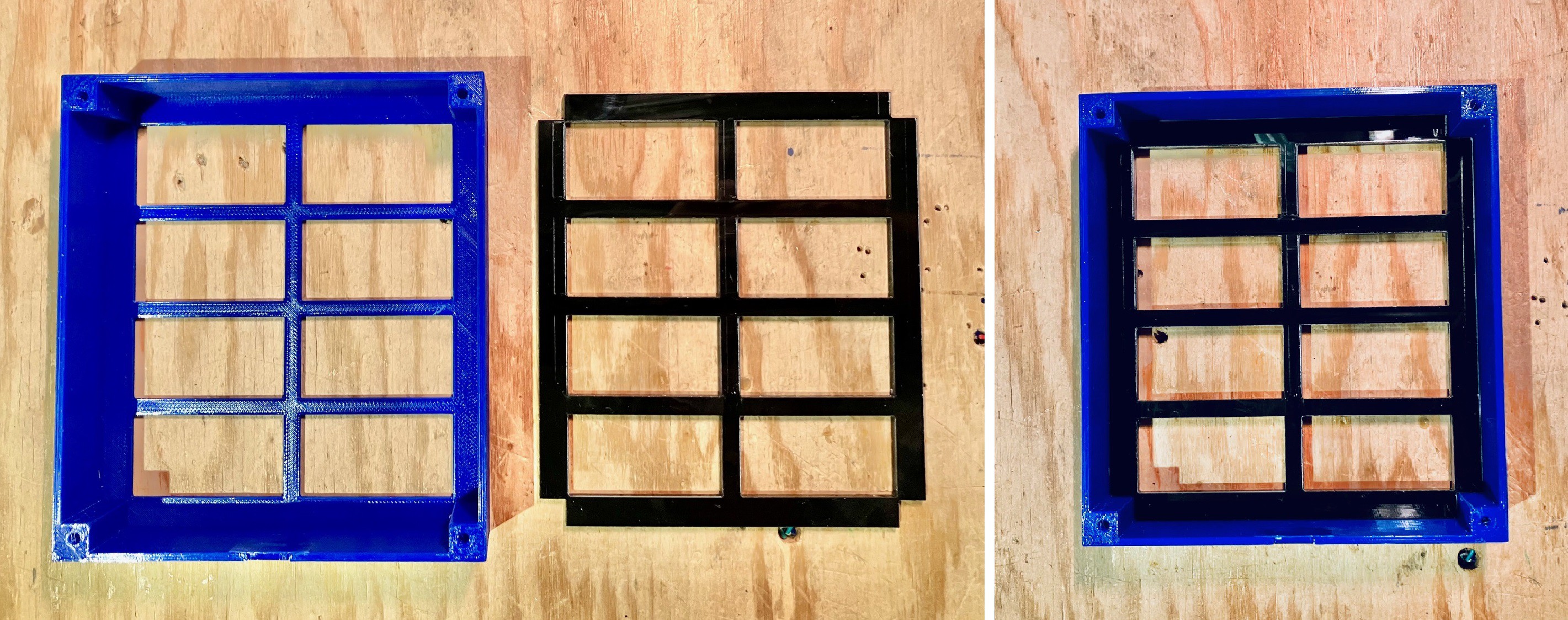
I thought that by eliminating the keycaps on this new version I would reduce the size of the MacroPad a lot. This turned out not to be the case, mainly because the "margins" around the Tile Holder Buttons needed to be larger to allow room for the wiring to be routed around.
The MacroPad 2 would be pretty much the same cost as A Tile Based MacroPad less whatever the no longer required keycaps cost (in my case about $8).
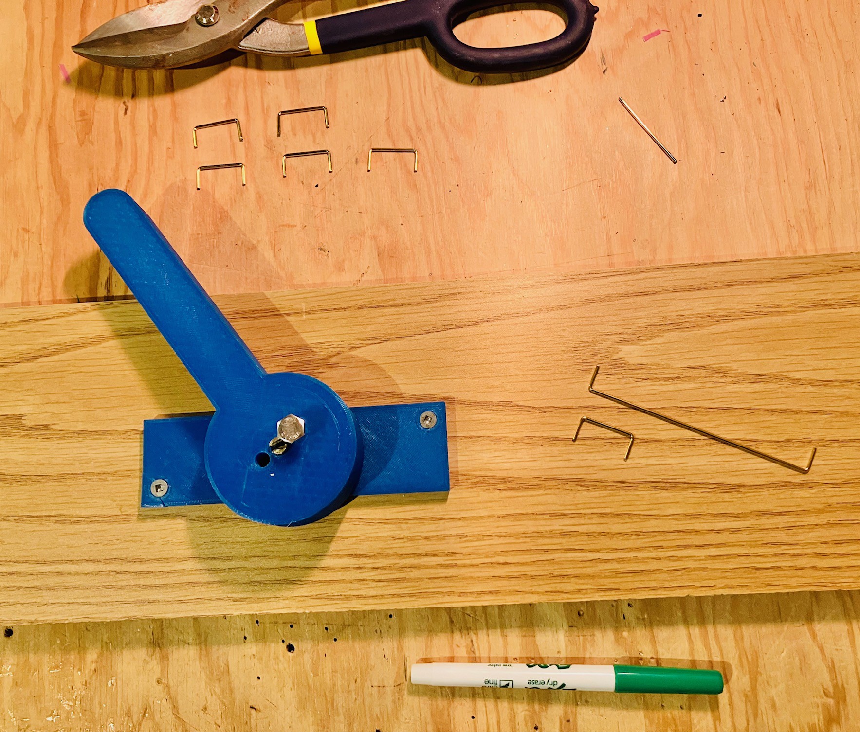
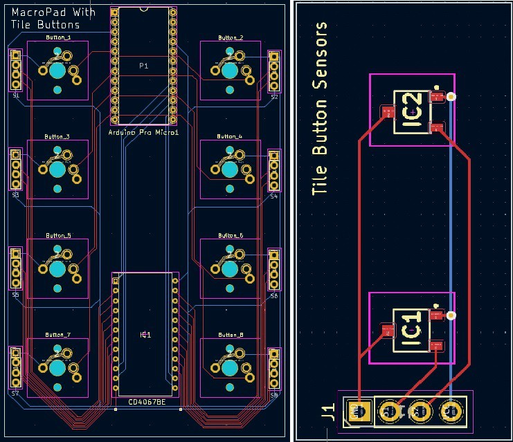
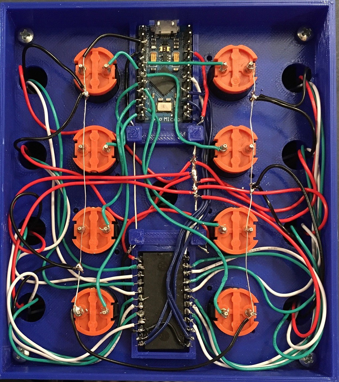
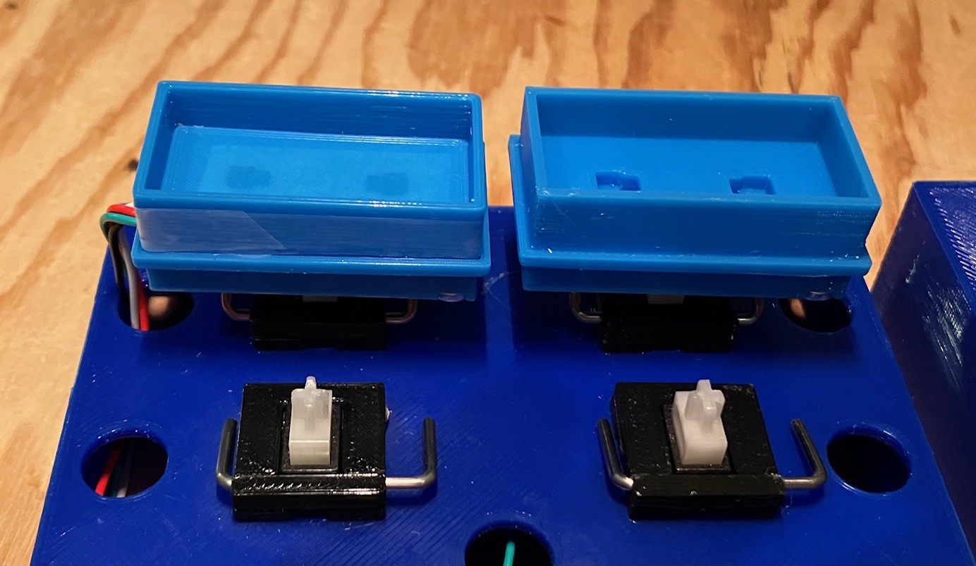
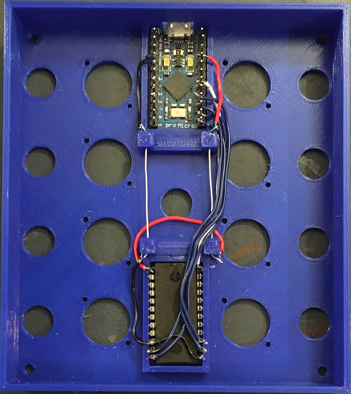
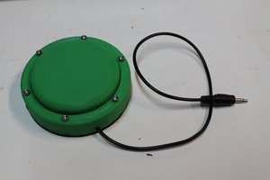
Wiring the Tile Holder Buttons was a pain and represents I think the weak point in the build. This is especially true since repeatedly pressing the buttons is going to put stress on the solder joints inside. Perhaps some hot glue would help. If I were doing it again I would probably design some small PCBs to hold surface mounted versions of the hall effect sensors.
So which version do I like the best? Well I love both my MacroPad creations equally well of course.
 Ben Brooks
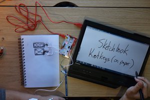
 BrettBuilds
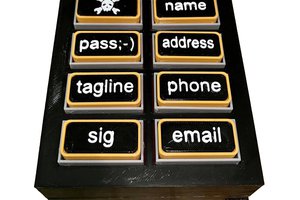
 Christopher