-
Transistor Audio Filter
08/11/2020 at 12:22 • 0 commentsThis article shows a transistor audio filter.
The filter is made from three Darlington pair transistor voltage followers.
Step 1: Design the Circuit
Connecting two of more capacitors in parallel reduces the current dissipation across each capacitor.
![]()
Calculate transistor input resistance Beta*re:
Beta*reB = Beta * (26*10^-3) / Ie
= Beta * (26*10^-3) / (Vs / 2 / Re1)
= 100 * (26*10^-3) / (1.5 V / 2 / 10,000 ohms)
= 17,333.3333333 ohms
Beta*reA = Beta * (26*10^-3) / (Ie / Beta)
= Beta * (26*10^-3) / (Vs / 2 / Re1 / (Beta + 1))
= 100 * (26*10^-3) / (1.5 V / 2 / 10,000 ohms / 101)
= 1,750,666.66667 ohms
= 1.75 Megohms
Calculate input resistance of the Darlington pair transistor voltage follower:
(We are ignoring the transistor input resistance Beta*re)
Ri = (Beta + 1)*(Beta + 1) * Re = 101 * 101 * 10,000 ohms
= 102,010,000 ohms = 102.01 Megohms
The transistor input resistance Beta*re will only add to the total voltage follower input resistance.
Calculate output resistance of the Darlington pair transistor voltage follower:
(We are ignoring the transistor resistance Beta*re)
Ro = Re || ((Rb1a || Rb2b) / (Beta + 1) / (Beta + 1))
= 10,000 ohms || (((1*10^6 ohms)||(10*10^6 ohms)) / 101 / 101)
= 88.3306392488 ohms
The transistor input resistance Beta*re will increase the output resistance slightly.
Calculate minimum low pass filter frequency:
FlpfMin = 1 / (2*pi*(Rlp1 + Rlp2)*(Clp1 + Clp2))
= 1 / (2*pi*(1,010,000 ohms)*(2*10^-9))
= 78.7895757881 Hz
Calculate maximum low pass filter frequency:
FlpfMax = 1 / (2*pi*Rlp1*(Clp1 + Clp2))
= 1 / (2*pi*(10,000 ohms)*(2*10^-9))
= 7,957.74715459 Hz
Calculate minimum high pass filter frequency:
FhpfMin = 1 / (2*pi*(Rhp1 + Rhp2)*Chp)
= 1 / (2*pi*1,001,000 ohms*(47*10^-9))
= 3.38289249244 Hz
Calculate maximum high pass filter frequency:
FhpfMax = 1 / (2*pi*Rhp1*Chp)
= 1 / (2*pi*1,000 ohms*(47*10^-9))
= 3,386.27538493 Hz
Step 2: Simulations
Transient 1:
![]()
Transient 2:
![]()
Full Spectrum Bandwidth:
![]()
Spectrum Low Pass Filter (LPF):
![]()
Spectrum High Pass Filter (HPF):
![]()
-
LED Indicator
04/16/2020 at 04:42 • 0 commentsThis article shows you how you can make a simple LED Indicator.
![]()
You can see the circuit working in the video:
Step 1: Design the Circuit
I have drawn the circuit in the old PSpice software:
![]()
The old PSpice software did not have the LED component. Thus I used three diodes instead to model each of the three LEDs. The R1a and R1b can be converted to Thevenin's equivalent circuit to calculate the maximum LED1 current:
Vth1 = Vs * R1a / (R1a + R1b) = 4.5 V * 3,900 / (3,900 + 100) = 4.3875 V
Rth1 = R1a * R1b / (R1a + R1b) = 3,900 * 100 / (3,900 + 100) = 97.5 ohms
IledMax1 = (Vth1 - Vled1 - Vbe2 - Vbe1) / Rth1
= (4.5 V - 2 V - 0.7 V - 0.7 V) / 97.5 ohms = 0.01128205128 A = 11.28205128 mA
The same method can be applied to calculate the maximum LED current of the other two LEDs.
Vth2 = Vs * R2a / (R2a + R2b) = 4.5 V * 3,300 / (3,300 + 120) = 4.34210526316 V
Rth2 = R2a * R2b / (R2a + R2b) = 3,300 * 120 / (3,300 + 120) = 115.789473684 ohms
IledMax2 = (Vth2 - Vled2 - Vbe2 - Vbe1) / Rth2
= (4.5 V - 2 V - 0.7 V - 0.7 V) / 115.789473684 ohms = 0.0095 A = 9.5 mA
Vth3 = Vs * R3a / (R3a + R3b) = 4.5 V * 2,700 / (2,700 + 150) = 4.26315789474 V
Rth3 = R3a * R3b / (R3a + R3b) = 2,700 * 150 / (2,700 + 150) = 142.105263158 ohms
IledMax3 = (Vth3 - Vled3 - Vbe2 - Vbe1) / Rth3
= (4.5 V - 2 V - 0.7 V - 0.7 V) / 142.105263158 ohms = 0.00774074074 A = 7.74074074 mA
Calculate the equivalent emitter resistance:
Req = Re || Rth1 || Rth2 || Rth3 = 38.5624852748 ohms
The is very low resistance. Thus you will need an additional transistor connected in parallel with the Q2 transistor to reduce the power dissipation and the maximum current to prevent possible transistor failure.
The minimum input resistance will equal:
Rin = Req * (Beta + 1) * (Beta + 1)
= 38.5624852748 ohms * 21 * 21 = 17,006.0560062 ohms = 17.01 kohms
A typical transistor current gain, Beta is usually equal to 100. Some transistors can have a typical current gain of 500. Current gain is influenced by:
- temperature,
- production tolerances,
- aging,
- biasing current.
More information on the Thevenin’s Theorem can be found here:
https://www.electronics-tutorials.ws/dccircuits/dcp_7.html
Step 2: Simulations
Simulations show that the minimum current is above about 5 mA. This should be just about enough to keep the third LED on.
![]()
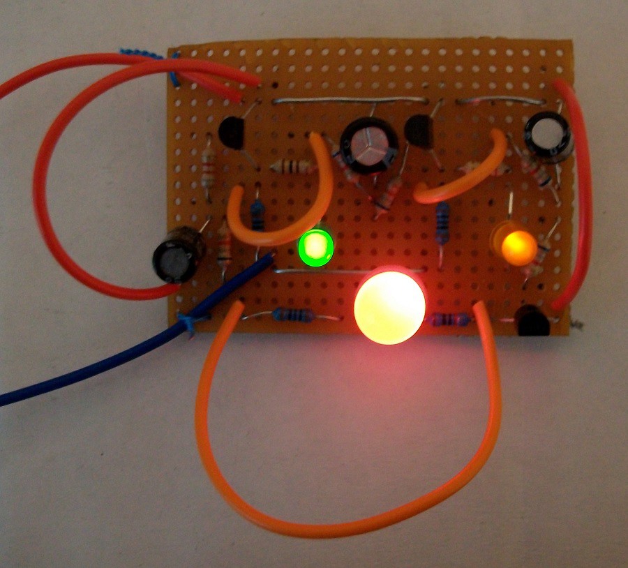
Step 3: Make the Circuit
I did not use a soldering iron. I twisted the wires together with pliers.
![]()
Step 4: Test the Circuit
I used 1 kohm potentiometer as a voltage reference. However, I believe that you can use a 10 kohm potentiometer if you do not have the 1 kohm variable resistor.
![]()
Conclusion
You can try adding additional LEDs to the circuit.
-
Three Transistor Oscillator
03/21/2020 at 20:04 • 0 commentsThis article shows you how to make a simple three transistor oscillator. The circuit is turning on time delay cascading transistors and LEDs.
![]()
An oscillator can be made from:
- one, two or three transistors (BJT, JFET, MOSFET or UJT),
- 555 timer (https://en.wikipedia.org/wiki/555_timer_IC),
- 8038 Integrated Circuit: https://en.wikipedia.org/wiki/Intersil_ICL8038,
- operational amplifier (https://en.wikipedia.org/wiki/Schmitt_trigger oscillator),
- relay,
- DC or AC motor/generator.
The circuit made in this article is known as a Ring Oscillator:
https://en.wikipedia.org/wiki/Ring_oscillator
You can see the circuit working in this video:
Step 1: Design the Circuit
I have drawn the circuit in the old PSpice Student edition software:
![]()
The software did not have LED components. Thus I used general purpose diodes. Keep in mind that this could have affected my simulations because general purpose diode voltage is 0.7 V and LED voltage is 2 V.
Calculate the maximum base current:
IbMax = (Vs - Vbe) / (Rc3 + Rb1a + Rb1b)
= 3 V - 0.7 V / (12000 ohms)
= 2.3 V / 12000 ohms = 225 uA
Calculate the minimum collector current for maximum base current:
The minimum collect current is for minimum current gain, Beta:
IcMin = IbMax * BetaMin = 225 uA * 20 = 4.5 mA
Calculate the equivalent collector to ground resistance.
Since the LED voltage does not increase about 2 V the maximum LED current is about:
Iled = (Vs - Vled1) / Rd1 = (3 V - 2 V) / 100 ohms = 10 mA
Therefore the equivalent LED resistance will be:
Rled1 = 2 V / 10 mA = 200 ohms
The transistor will be powering an equivalent collector to ground resistance of:
Rceq1 = Rc1 * (Rd1 + Rled1) / (Rc1 + Rd1 + Rled1)
= 10000 * (100 + 200) / (10000 + 100 + 200)
= 291.262135922 ohms
Will the transistor saturate?:
Icmax = Vs / Rceq1 = 3 V / 291.262135922 ohms = 10.3 mA > 4.5 mA
That means that the transistor will saturate if the minimum current gain (Beta) is above assumed value of 20. We can raise the collector current by increasing the supply voltage. However, this will not be necessary because the LEDs will burn fail. You can raise the supply voltage if you increase the value of the Rd resistors. This is how you calculate the Rd value:
Rd = (Vs - Vled) / Iled
= (3 V - 2 V) / 10 mA = 100 ohms
Calculate the maximum and minimum time constants:
The capacitor is considered to be fully charged after 5 time constants.
The maximum time constant is at maximum resistance seen by the capacitor. This occurs when when transistor is OFF.
T1 = (Rceq1 + Rb1a) * C1
= 0.60689320388 seconds
The minimum time constant is at minimum resistance seen by the capacitor. This occurs when the transistor is ON:
The transistor input can be modelled as an equivalent resistance:
(https://forum.allaboutcircuits.com/threads/small-diode-emitter-resistance-re.59624/)
re = 26 mV / IeBias
= 26 mV / IcMax
= 26 mV / 10.3 mA
= 2.52427184466 ohms
rbeMin = re * Beta = 2 * 20 = 50.4854368932 ohms
rbeMax = re * Beta = 2 * 500 = 1,262.13592233 ohms
T2min = (Rceq1 + Rb1a)||(rbeMin + Rb1b) * C1
= 0.27224645381 seconds
T2max = (Rceq1 + Rb1a)||(rbeMax + Rb1b) * C1
= 0.41443762164 Seconds
The frequency of oscillations can be highly influenced by the transistor current gain for another reason, if the current gain is low. It is the current gain that affects transistor the output and thus the oscillation state (ON or OFF) of the next cascade transistor.
Calculate the maximum capacitor voltage:
The capacitor can only reach its maximum voltage if the feedback loop is disconnected. The LED will be OFF and its equivalent resistance (Rled + Rd1) will be near infinity. The transistor is a current source. Therefore:
Vc1Max = (Vs - Vbe) / (Rc3 + Rb1a + Rb1b) * Rb1b + Vbe
= 2.3 V / 12000 ohms * 1000 ohms + 0.7 V = 0.89166666666...
Read more »


 mark
mark Kristjan Berce
 James Pae
 omersiar
 jascha ehrenreich
 davedarko
 Elecia White
 Chris Gammell
 Sergei V. Bogdanov
 Carl Bugeja
 Ashley Warren
 Amal Mathew
 Jordan Lau
 xango
xango ivorivetta
Hi,
It was a great method of calculation, I liked the method of fine detailing and it is a professional method that avoids you from making math mistakes.
Good luck and Keep going!
Abdul