 Mario Lukas
What is Open Exposer?
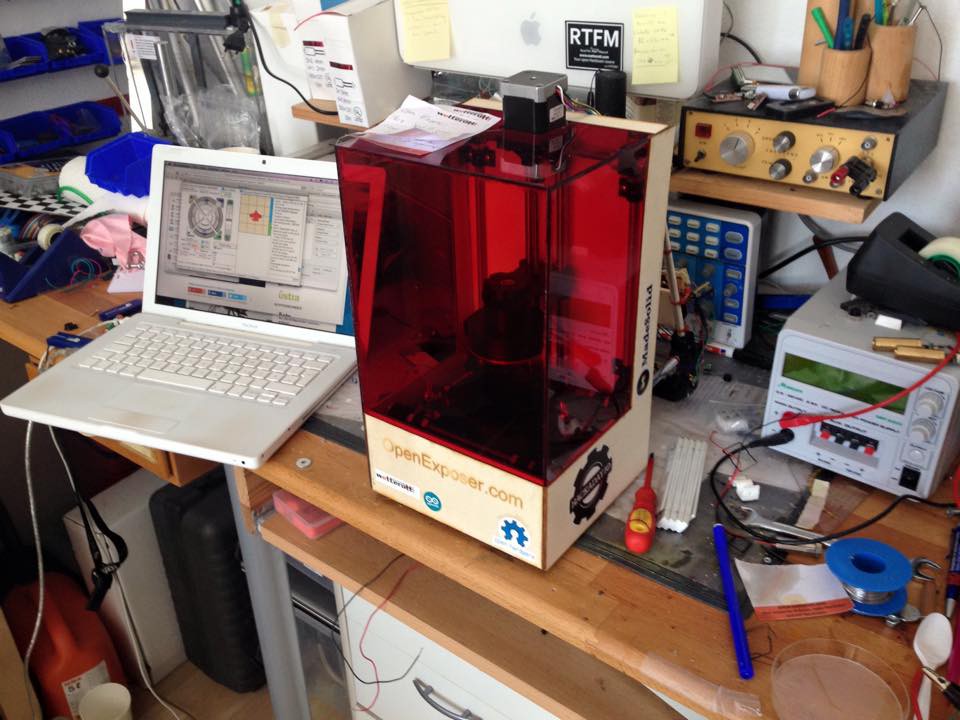
The Open Exposer is a Open Hardware device which can be used for multiple laser exposure applications. For example you can build high resolution 3d printers, pcb exposure devices and much more...
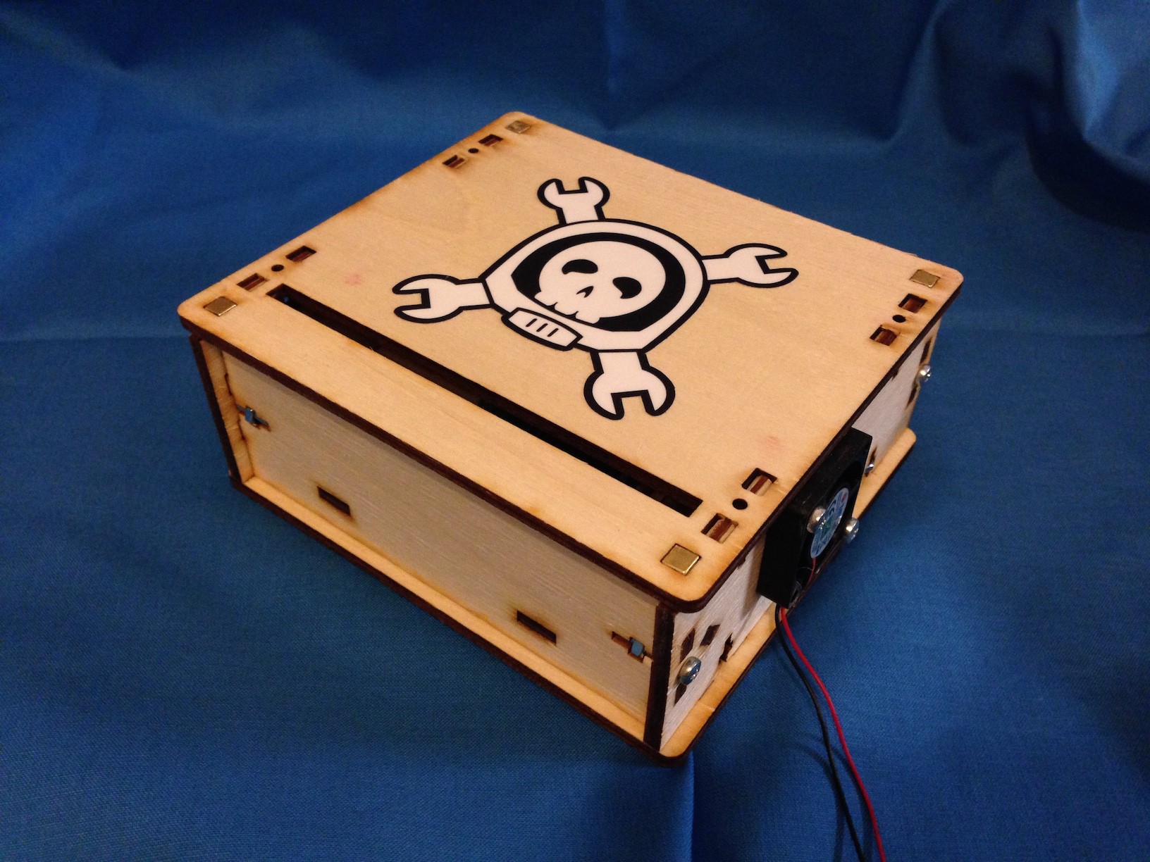
How does it work?
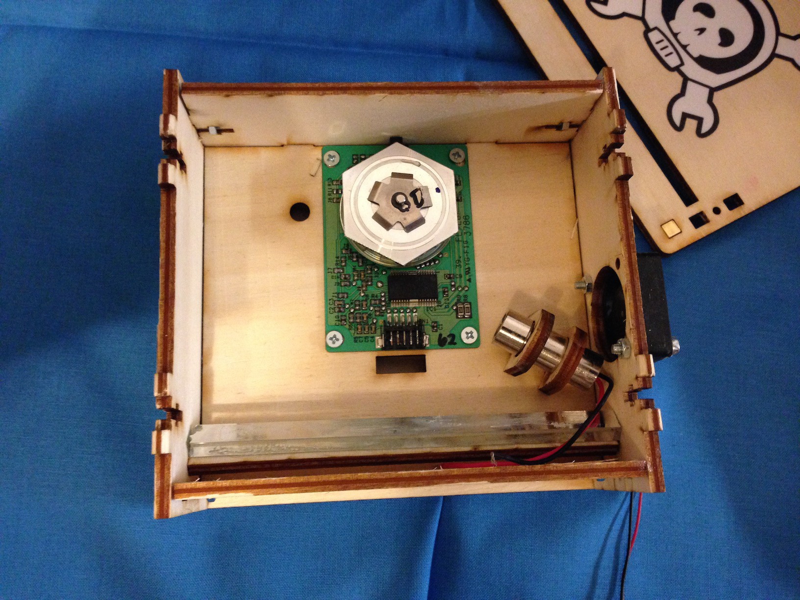
The main components of the Open Exposer are a laser and a polygon mirror. The principle is well known of laser printers. The polygon mirror is used to produce a laser line. An Arduino is used to control the device. By quickly switching the laser on and off it is possible to generate any line pattern. The magic happens in the Arduino Firmware. You only have to set a Flag in Firmware for your polygon mirror.
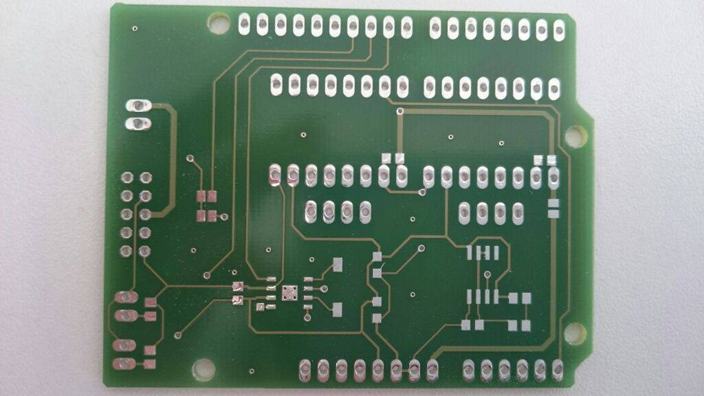
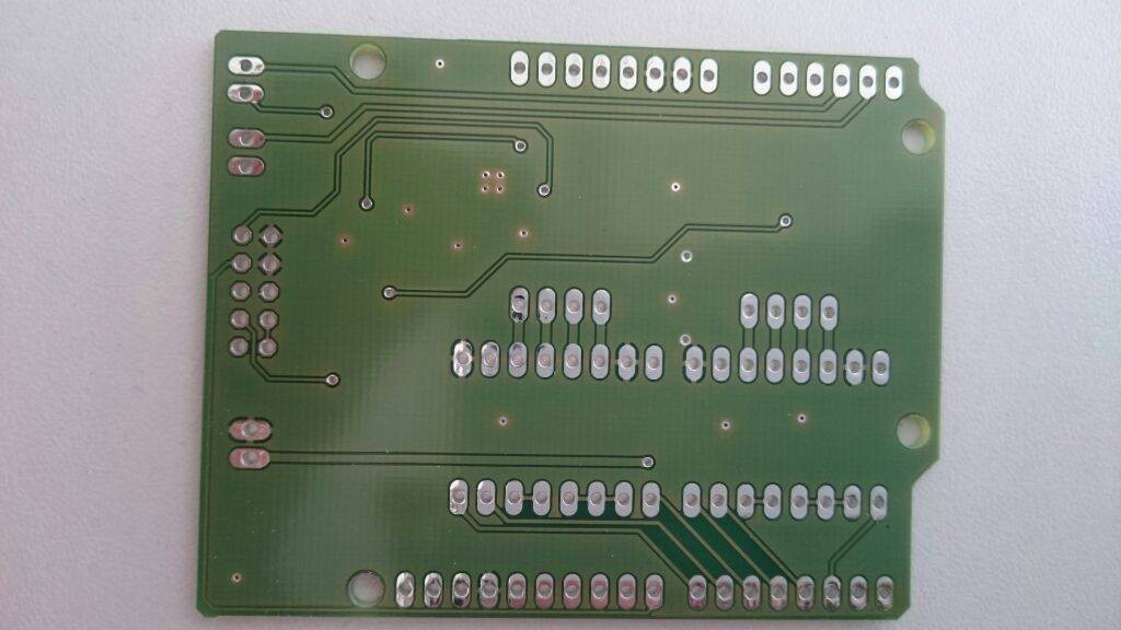
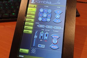
The Arduino with my self-designed Open Exposer shield is used to control the device. The Open Exposer can interpret G-Code. So it is easy to control.
The Arduino shield will have pin outs for two stepper motors and different I/O's, which can be used for other sensors like end stops.
What can i do with Open Exposer?
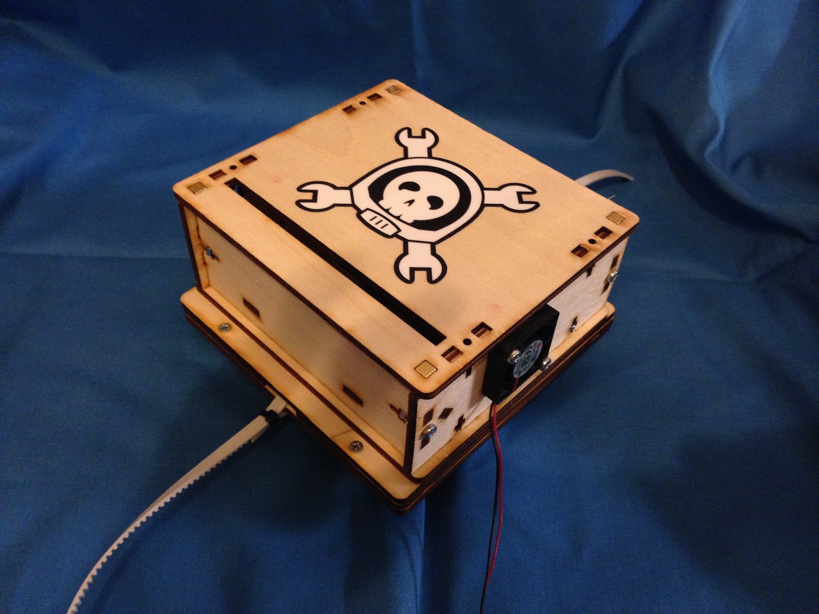
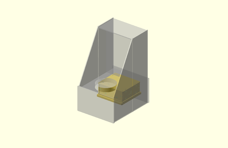
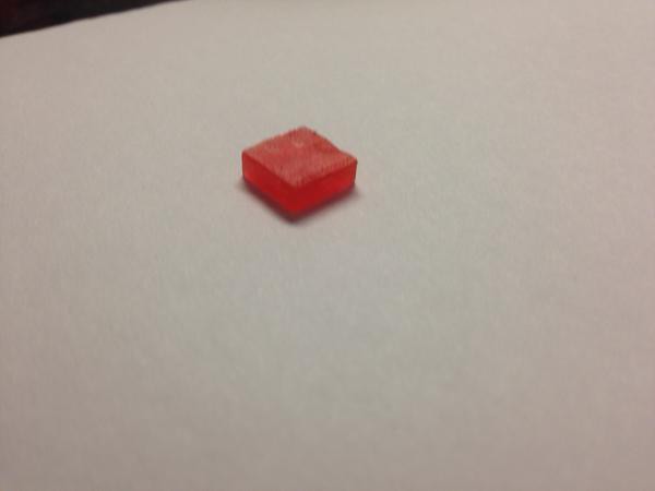
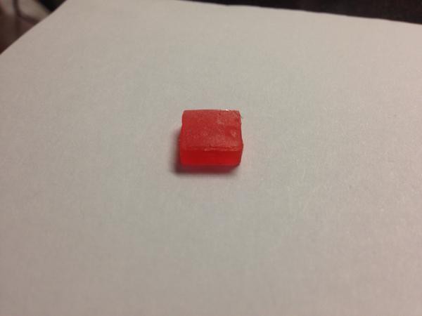
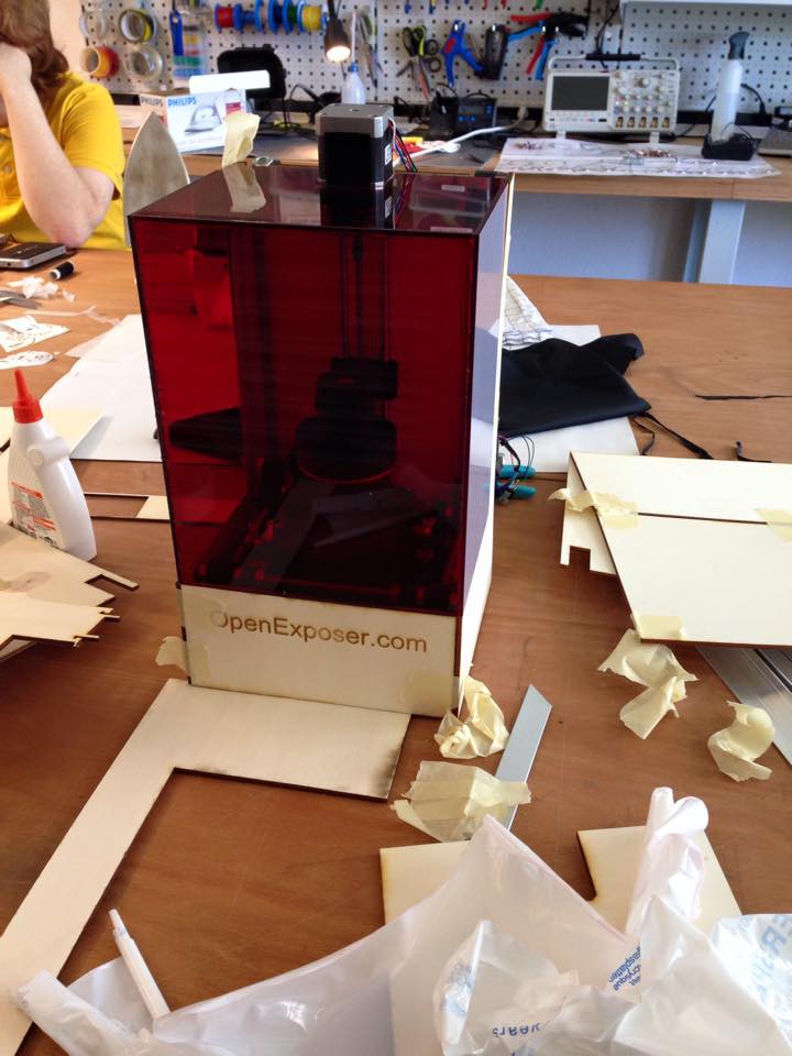
My favorite use case is a high resolution 3D resin printer, because it will be realizable for under 500 $. With the new design (laser cut parts) it will be easy to produce and easy to assemble. That is the reason why the first "prototype" extension i have built was a 3d resin printer.
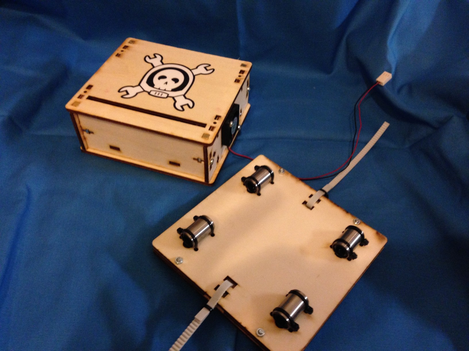
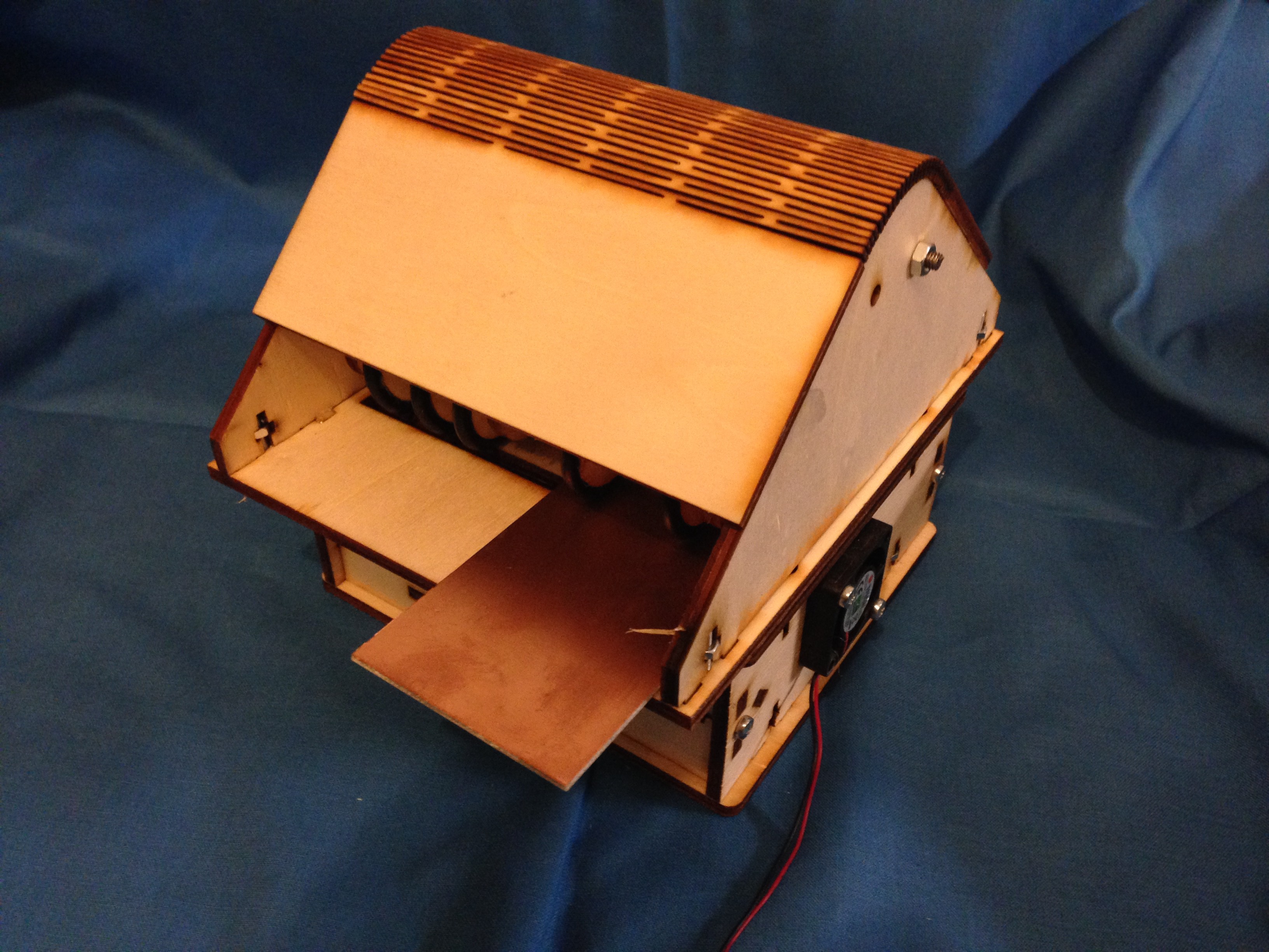
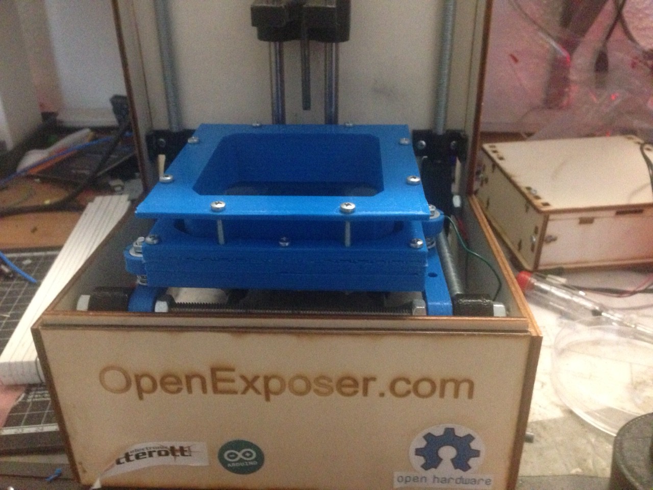
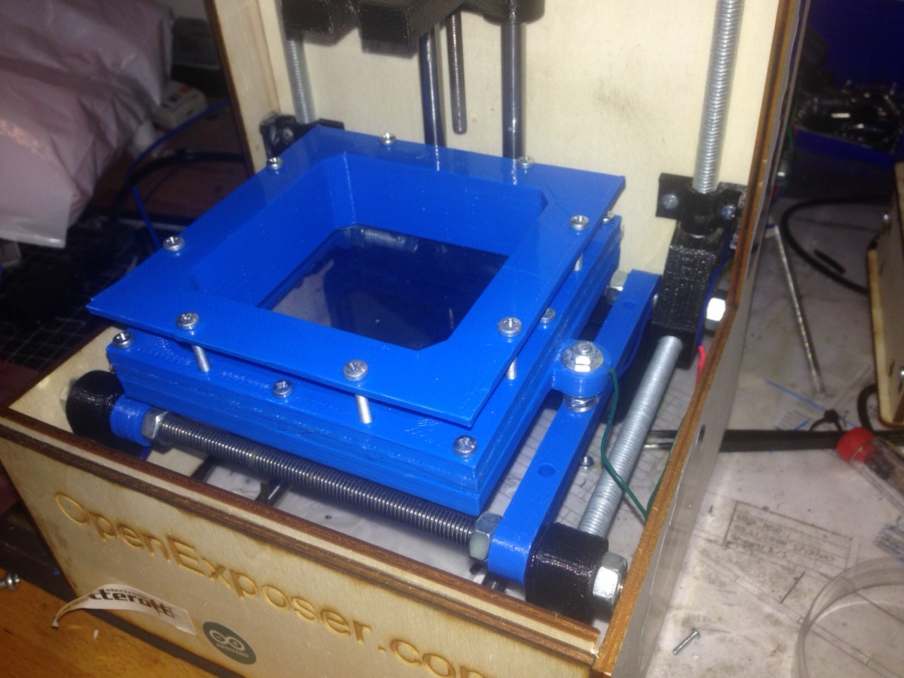
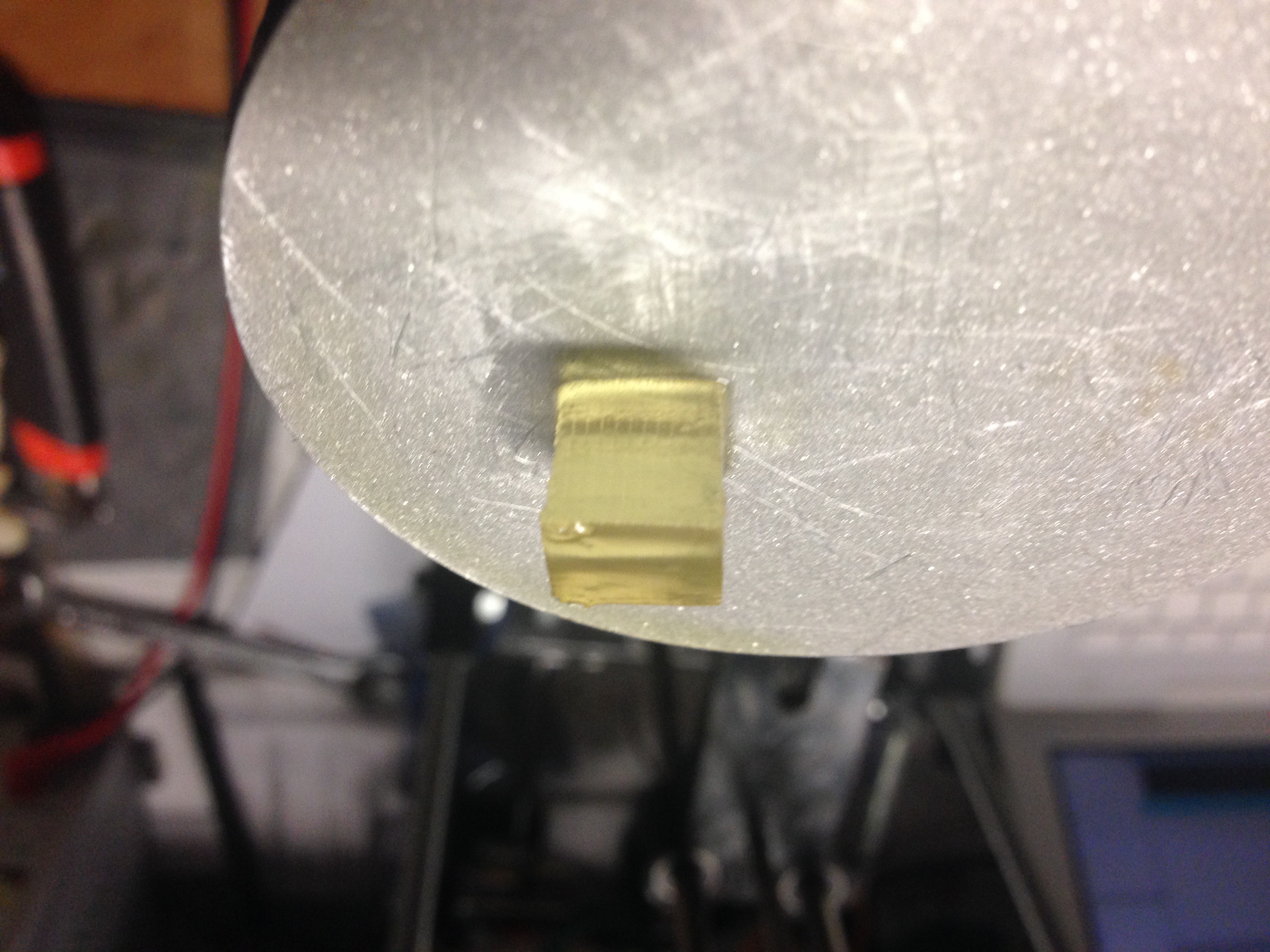
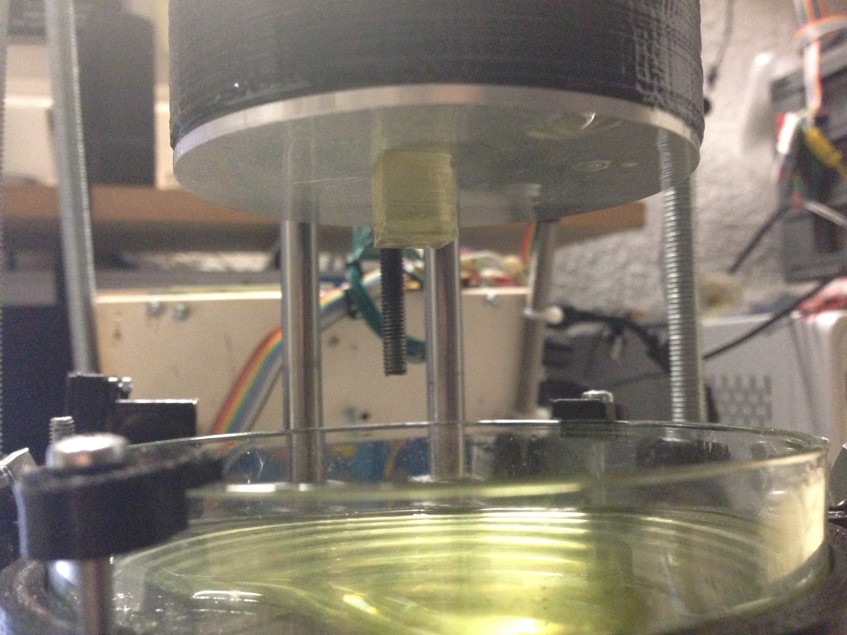
 The pictures above are showing the bearing extension which is used for the 3D resin printer.
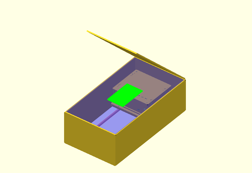
The following picture shows a possible pcb extension. It will work like a laminator. Some rolls push the photo sensitive pcb over the laser slot.
Open Exposer is an easy to build and very cheap device, because it uses standard components.
System Design
Hardware
The main unit is controlled by Arduino and the Open Exposer shield. The Open Exposer shield can carry two stepper drivers. It also contains the laser driver circuit. An additional micro controller is used for controlling the polygon mirror speed. In a later version the Arduino and the Open Exposer shield will be replaced by a single pcb.

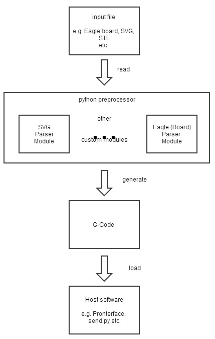
Software
The software consists of four parts. The first part is the arduino firmware, where all the hardware controlling magic happens.
The second software part is the third party software which is used to produce the exposing data. This can be a 3D CAD Software like OpenScad , Slic3r , Eagle and so on...
The third software is the Open Exposer G-Code generator. The Open Exposer G-Code generator offers an interface for custom modules. It is used to generate G-Code from your third party software data.
The fourth software part is the host software which sends the the generated G-Code to the Open Exposer. You can find a lot of G-Code sending host software in the internet.
Some Example Videos of different prototyping stages.
Open Exposer first firmware test (exposing)
Open Exposer as 3D Printer Prototype exposing Test.
Open Exposer use case examples
High resolution resin 3D printer.
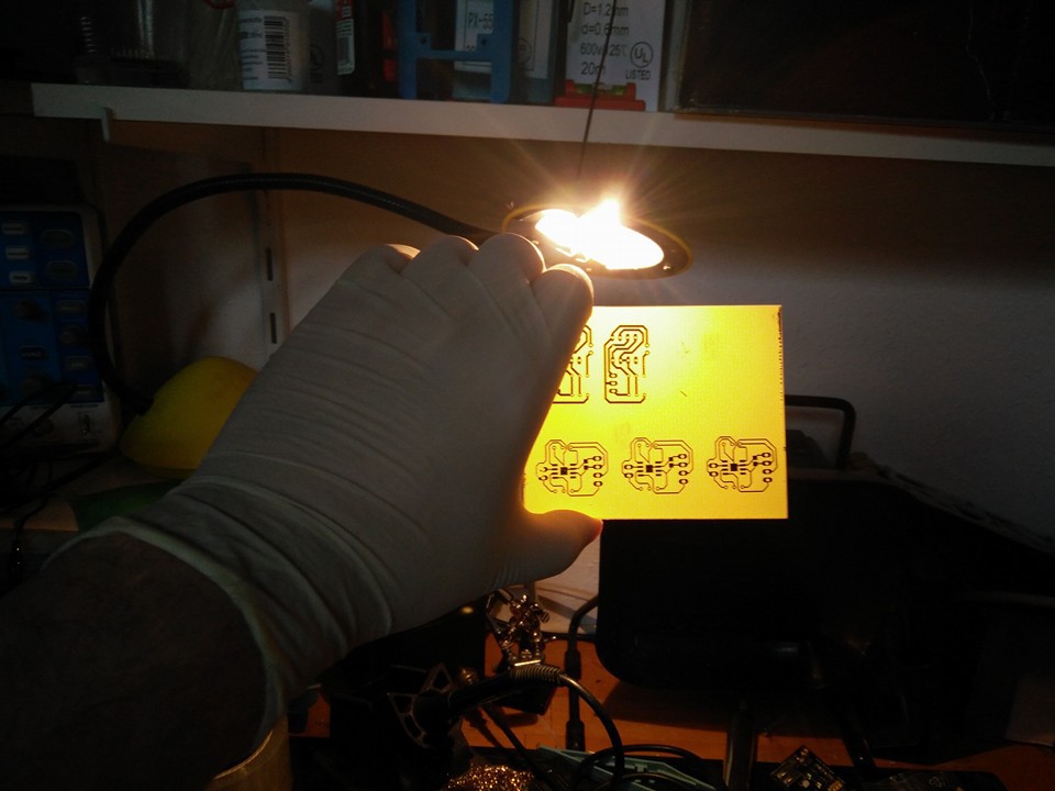
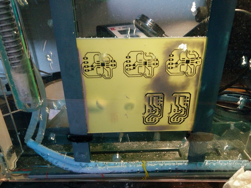
PCB exposure device.
Used Open Components:
Softtware:
- Python
- Slic3er
- Accel Stepper Library
- Printrun Tools ( as host software )
- Hardware:
- Arduino
- Laser Driver (die4drive)


 dannyvandenheuvel
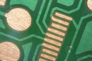
 Terje Io
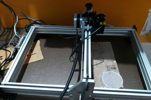

 Cadmium
Why dont you use the laser that comes in the photocopier ? Great and astonishing project