 fl@C@
fl@C@

Note: This log entry is a living document. I'll be updating this post to reflect the current configuration as time goes on.. There will also be a log at the end of the post noting modifications to the log, etc..
UPDATED-----> 10.15.2014

This log entry is where I will keep current information regarding the schematic, board layout and other details about the imagingBoard electronics and firmware.. I will reference this log entry in the 'details' section of the project page.. This log entry will probably change from time to time to reflect the current status of the imagingBoard. If you're interested, it might be worth a bookmark..
The function of the powerControlBoard is as follows:
- Accepts power from main power supply and distributed it to other boards
- Contains the L298 HBridge for the imaging and cuvette peltiers
- Current Sensor monitors peltier current draw
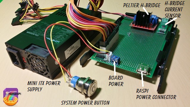
Here is what the current powerControlBoard looks like..
The eagle files are located in the gitHub repository..
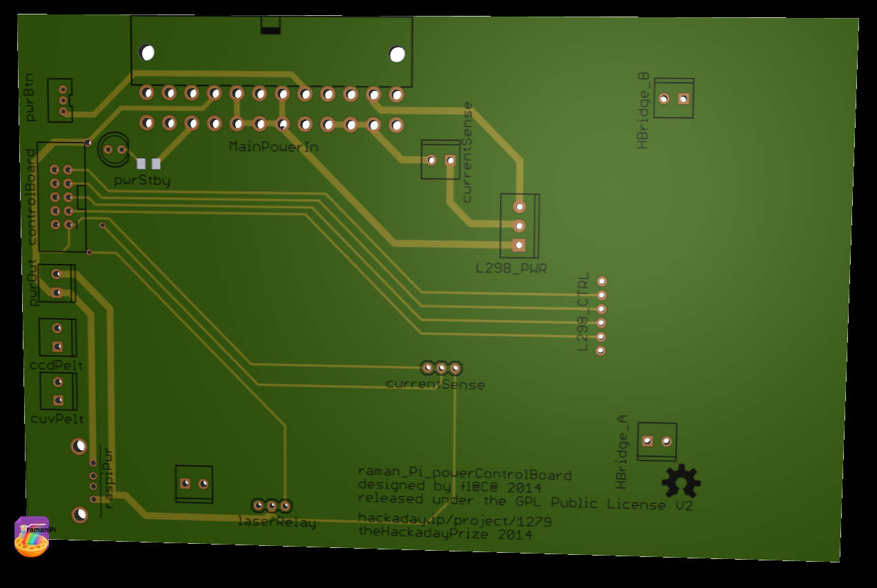
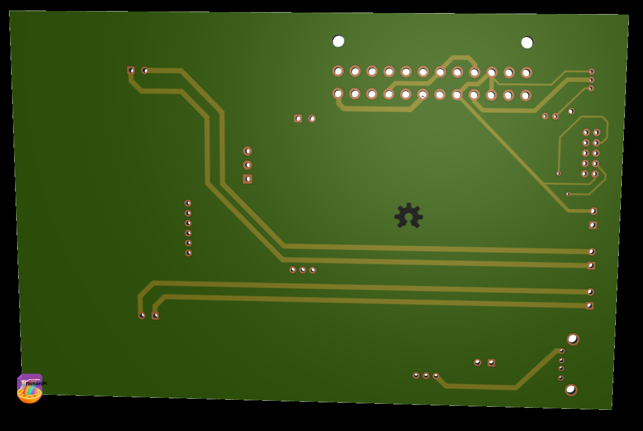
Here is the board rendering..
Top
Bottom
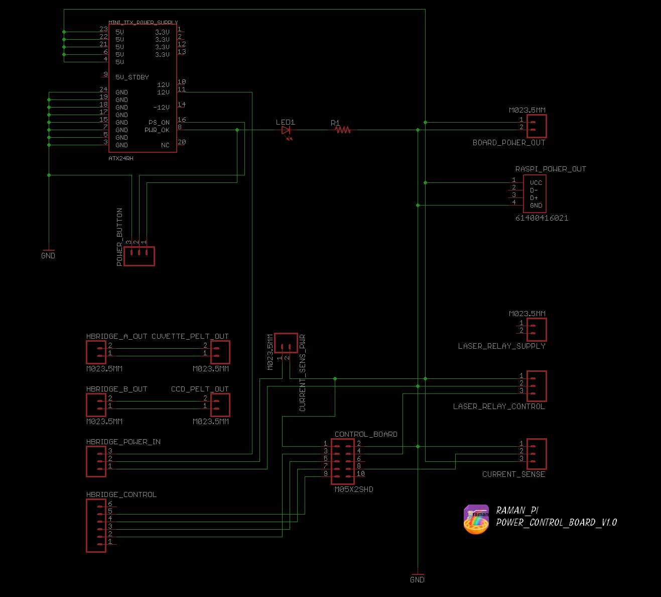
Here is the schematic..
The eagle files, and the firmware are located in the gitHub
- Hardware: gitHub repository
The board consists of the connector for the ITX power supply, power connector for the raspberryPi, power connector for the other boards, and a control cable from the controlBoard for the H-Bridge and Current Sensor both of which also live on this board..
Keep an eye out, since there will be updates here...!

UPDATE LOG:
09.28.2014 - Added living document info
10.15.2014 - Added new schematic and board renderings
Discussions
Become a Hackaday.io Member
Create an account to leave a comment. Already have an account? Log In.