 James Newton
-
1Step 1
See:
http://techref.massmind.org/techref/io/SERVO/BOBPID.htm
for the most up to day instructions. Those listed here may be out of date.
These instructions assume you are using the BOB PID PCB from the link above. You could also build this on a perfboard or whatever. I've added the PIC pin name to the tables for that reason.Note: Most components are installed on the underside of the PCB... The side with "U1 PIC"
-
2Step 2
Z-axis
PinSignal from BOB PCB
All even pins are groundPIC Pin 1 "E" /Enable RC7 3 "D" PWM Drive (not direction) RC2 5 "S" Direction (not step) RA4 7 "-" Ground GND 9 "+" +5 Logic power (if needed) VCC Motor Driver Output via Z Axis cable
[ ] Install a 10 pin 2x5 header over the Z axis on JP3. On the boards underside, this is the 2nd from the right block of 2x5 pins in JP3 with "Z" just below it. Note that we swapped the standard functions of Step / Direction to support the PIC. For a PMinMO stepper driver, you must swap pins 2 and 3 in the cable. Our H-bridge driver will have those pin swapped, for a straight cable.
-
3Step 3
X-axis
PinSignal from BOB PCB
All even pins are groundPIC Pin 1 "E" /Enable RB6 3 "D" Direction RC0 5 "S" Step RA1 7 "-" Ground GND 9 "+" +5 Logic power (if needed) VCC Step / Direction input from motion controller via X Axis cable (if desired)
[ ] Install a 10 pin 2x5 header over the X axis on JP3. On the boards underside, this is the far left block in JP3, starting from pin 1. This is PMinMO standard, so the Pololu adapter cable works nicely.
-
4Step 4
J2
Pin
Signal from BOB PCBPIC PIN 1 +5 Logic power (if needed) VCC 2 CTS (unused) RB4 3 Ground GND 4 TX <- USB/Host RB5 5 RX -> USB/Host RB7 Serial Console: To talk to the controller via USB - TTL serial (Required to set the PID constants):
[ ] Install J2 RLC header on the top side for USB / serial communications to a host. The host is used to tune the PID loop, provide motion commands for test or use, and update firmware via the bootloader. Note that pin 4 TX is data FROM the USB/Host going TO the PID controller. RX is TO Host FROM PID. E.g. TX and RX are backward from the FTDI Friend connector. Oops... but screw them anyway.
-
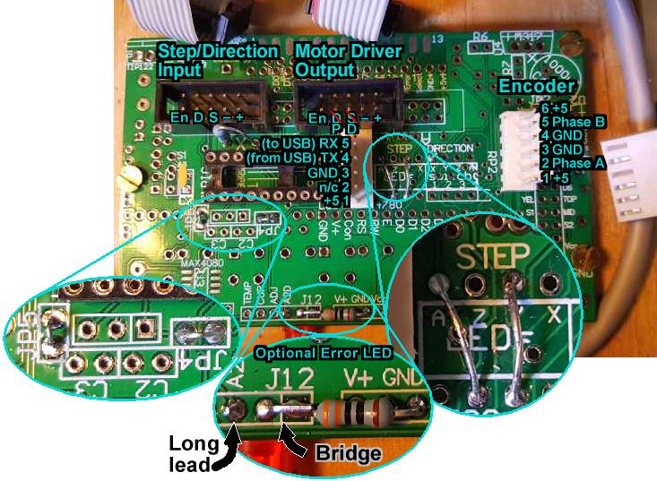
5Step 5
![]()
Pin on
BOB
LabelPIC Pin Pin on
ENC1Encoder
Signal1 or 6 +5 VCC 5 5V 2 Y LED RA0 3 PhaseA 3 or 4 GND GND 4 GND 5
(not 4)Z LED RA5 2 PhaseB Quadrature Encoder:
[ ] Install a 1x6 (or 1x5, pins 6 & 1 share +5) header over the holes for the Z and Y LEDs. (see picture) The polarity tab should be towards the outside edge of the PCB making pin 1 the square pad toward the lower edge, near the "Y" on the front, or "D2" on the underside, of the PCB. See the picture below. This brings power, ground, and data lines originally for those LEDs out to a Quadrature Encoders; we can use them as inputs instead. The cable for the MassMind ENC1 Encoder is shown:
-
6Step 6
This step and the next two are just for the PIC BOB PCB...
![]()
[ ] Install JP4 and JP5 on the underside of the PCB, about an inch from the left, just below U1. See left bubble in picture.
-
7Step 7
[ ] Install a jumper over the RP2 LED network from STEP Y to the corresponding pin on the bottom side of RP2. See right bubble in picture.
-
8Step 8
[ ] Install a jumper sideways over RP2 from STEP A to the pin NOT directly on the other side of RP2, but one place over, towards the Y jumper you just installed. See right bubble in picture.
-
9Step 9
[ ] Install C4 (upper right corner, not shown in photo) and C7 (just left of U1 "PIC") to ensure stable power and avoid unexpected resets. Despite the value indicated on the PCB, C4 can be any good sized electrolytic capacitor (e.g. 220uF to 1000uF). Note it's long lead should be installed in the square pad nearest the "+" and just above and right of "C4".
-
10Step 10
[ ] The PIC 18F14K22 is installed as U1 PIC on the bottom side center left. The notch on one end of the chip should match the notch on PCB and face the U1 PIC text. Be sure it is programmed first (Source code in github). The chip provided with the kit is already programmed and includes a bootloader for future firmware updates.
BOB PID Servo Controller
A VERY cheap, tested, working, PIC based P.I.D. PID servo controller, for stepper replacement e.g. RAMPS, Pololu plug compatible drop in.

Discussions
Become a Hackaday.io Member
Create an account to leave a comment. Already have an account? Log In.