 peter jansen
Another quick update after a weekend marathon of board layout!
Modular Sensor Boards
Recall that in Step 2: Concept and Industrial Design, we decided that the amount of sensing area for a given case size could be maximized by using all sides of the device for sensors. This allows us to design a smaller, more portable device, but also has a bunch of other design benefits, including modularity. By having four separate sensor boards, we can offer our users an upgrade path, and allow folks in the open source community to easily add sensing capabilities without sacrificing the benefit of the existing sensors. From a design standpoint, it also allows us to perfect the design of individual boards without having to do another turn of the entire sensing system, which saves a lot of time. Since the clock is ticking, it's all about making our mistakes cheaply.
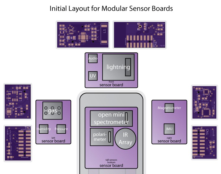
I was able to layout the boards more compactly than I had originally thought, reducing their height by 5mm to 15mm -- and ultimately this may reduce the thickness of the entire device by 5mm, which is fantastic. The boards themselves are:
- Atmospheric Sensor Board (left): Containing the ambient temperature, pressure, and humidity sensors, as well as the multigas sensor.
- Inertial Measurement Unit and Magnetometer Board (right): I've coupled these two together purposefully. Inexpensive magnetic field sensors have really advanced in the last decade, moving from simply sensing field strength to giving a 3-axis measurement, allowing you to roughly determine the field direction. The MPU9150 IMU also happens to contain a magnetometer, and I'd like to experiment with advancing this even further by getting range data using the two magnetometers and a bit of geometry.
- Lightning and UV Board (front): The lightning sensor contains an RF antenna and needs a bit of room, so I've placed it on the front. I've also incorporated a UV sensor that's capable of determining the UV index. The UV sensor also contains some very coarse near-field IR distance measurement, and so I've included the LED for this, just incase. This front board also has a little bit of extra width, which was perfect for the MEMS microphone and amplifier circuit.
- Spectroscopy and Thermal Camera Board (bottom): I still have to layout this board, which will house the 3D Printable Mini Embedded Spectrometer, a light source, a low resolution thermal camera, and likely a linear polarimeter. I've had so much luck reducing the height of the rest of the sensor boards, I'm rethinking the layout, and seeing if I have enough room to lay down the spectrometer (saving a good deal of height), and incorporate the polarimeter on the back side of the board the 0th diffraction order so that everything's on the same optical path. That would be very exciting!
In general, I think there are two remarkable things about the sensor board design here. The first is that there's a very low barrier to entry into making your own sensor boards. Three copies of a given sensor board is only around $3 (shipped!) from OSHPark, and only absolute requires a header that's $2 in single quantity, meaning that folks can really and genuinely get into experimenting with rolling their own boards even on a serious budget. Second, the sensor connectors are mirrored, so that you can plug any sensor board into any of the 4 sensor connectors (left, right, front, or bottom), meaning that folks could conceivably mix and match with their own custom designs or upgrade as they see fit with minimal issues. That's great!
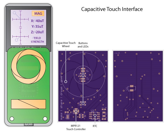
Capacitive Touch Interface Board
I like to include something new on each project that I've never used before, to get out of my comfort zone and gain a bit of breadth. In the design concept I decided to use a capacitive touch wheel as the primary user interface mechanism, with a few buttons for a tactile "click" experience when selecting items or moving backwards in the user interface.
After a great deal of research into capacitive touch wheels and parts, I settled on the MPR121 11-channel touch controller. There are fancier controllers out there that will automatically do the wheel calculations for you, but those parts were a little harder to source, and the central-mass calculations shouldn't be too computationally heavy anyway. I figured that more capacitive elements in your wheel equates to a higher wheel resolution, so I opted to use 8 segments, which is the near the high end of what I've seen any other designs use.
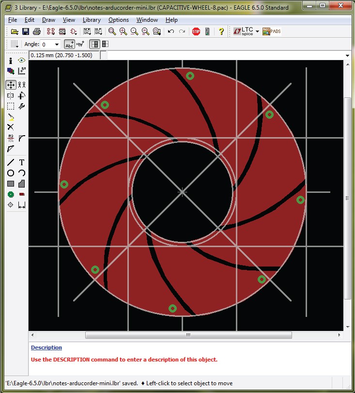
Part of getting out of my comfort zone here is actually drawing the wheel in Eagle CAD. I'd heard that they added in custom pad shapes in Version 6, but hadn't had the opportunity to learn how until now. It turns out it's as simple as drawing polygons around existing pads, which is a snap! This capacitive wheel is about 34mm in diameter, with an 8.5mm track width (which an appnote I read suggested as a good width for average finger size).
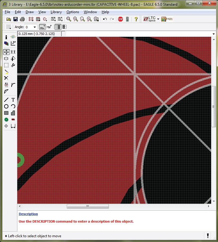
I'll admit that trying to make perfect curved arcs in the shape of the 8-segment twisty wheel really was a noodle scratcher for a while. I had zoomed out in the part and put my finger over the screen trying to eyeball the ideal ratio of curvature-to-distance for a finger being just over three pads at the extreme, and two pads nominally.
Being used to vector drawing packages like Adobe Illustrator, which is a beautiful piece of illustration software, it was a bit frustrating to deal with the limited arc drawing options in Eagle -- but of course it's a PCB package, not something meant for arbitrary vector drawing, and the folks at Cadsoft have done a really excellent job making Eagle extensible through scripts and transitioning the design format to an easily read XML. I didn't have time to put together an Eagle script to generate arbitrary perfect touch wheels, so the pragmatist in me ("make your mistakes cheaply") just set the grid resoution to 0.125mm, and traced over a wheel whose shape looked good. The results (above) are pretty good. I'm usually a bit of a perfectionist when it comes to laying out traces, but I decided that if approximating circles with lines was good enough for Sir Isaac Newton, it's good enough for me -- especially if the maximum it's out will be 0.125mm, or about 100 microns! Not bad for being more-or-less hand drawn. :)
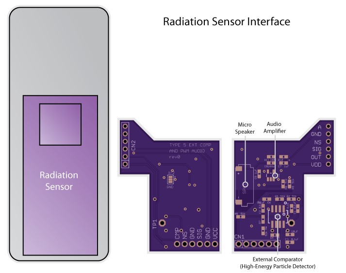
Radiation Sensor Interface Board
The final board that's off being made at OSHPark this week is the Radiation Sensor Interface Board for the Type 5 High-Energy Particle Detector by Radiation Watch. Off the shelf these detectors appear to have a detection threshold somewhere around 60 to 80keV -- that is, the sensor will only detect photons with at least 60-80keV of energy, leaving it largely sensitive to only to gamma rays and the most energetic x-rays. For my Open Source CT Scanner project I had to modify these sensors to be much more sensitive to the lower-energy photons emitted by common radioisotopes. With a special backpack interface board I was able to get the detection threshold down to around 30keV, making the detector sensitive to much of the hard x-ray region, and generally much more useful for a bunch of applications.
Here I've placed this circuit onto a backpack board that sits on the back of the Radiation Watch Type 5 sensor board, and takes raw input directly from a test point on their board, and pushes it through a more sensitive detection circuit. The board is a slightly odd shape to ensure clear access to the battery connector on the left side of the motherboard. As a quick aside, this board also contains a small audio amplifier and micro speaker (only 6mm x 12mm) for generating PWM audio from the PIC32.
I'd though about using a piezo buzzer, but I think it'd be fun to havedecent sound capability. And honestly, I think it'd be more compelling if it sounded like a serious scientific instrument instead of a greeting card when it was alerting you that you'd just ventured a little too close to a nuclear reactor... Which is to say nothing of the sound for a space invaders clone someone is bound to create. :)
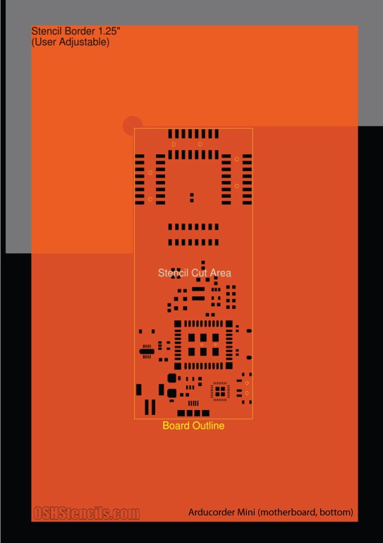
Solder Stencils
The solder stencils are also on their way from OSHStencils, and really make the job much easier. Where it used to take the better part of an hour to dot solder blobs onto 0603 pads and tweeze out excess paste from the TQFP pads, with a stencil you can do the same in only a minute or two. I'm still working on my technique -- I find that the 0.4mm/0.5mm pitch TQFP pads tend to get smeared and bridge without a little cleanup of the solder before reflow, but it's still much easier.
Being from the north, I tend to clean my stencils with a few drops of vodka, which led me to the strange discovery that solder paste, vodka, and mylar together smell almost exactly like potpourri. I have no idea why this is, unless my engineer of a father happens to hide rolls of solder in the holiday decorations. Maybe a future sensor board will contain a mid-IR spectrometer and be able to shed some light on the chemistry involved.
Thanks for reading! I'm expecting the motherboard and the rest of the components to arrive later this week, which means that the next update will very likely include actual hardware, which is fantastic! Thanks to everyone who's been following the project, and stay tuned!
Discussions
Become a Hackaday.io Member
Create an account to leave a comment. Already have an account? Log In.