 peter jansen
A quick update, with some of the high-risk high-gain aspects of the project!
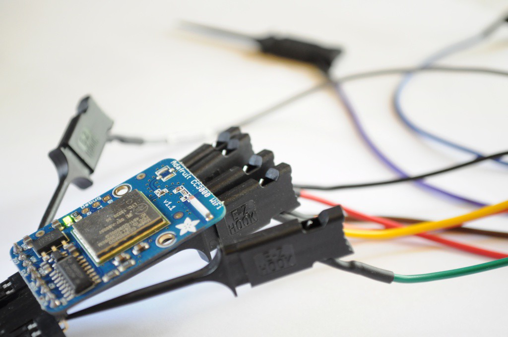
CC3000 WiFi Module and ChipKit Library Port
It's great to get out of your comfort zone and learn new skills or expand your familiarity with different aspects of design. For me, in addition to the capacitive touch wheel, I decided to include the popular CC3000 WiFi module from Texas Instruments. I think connectivity fits a lot of the use cases for a science tricorder-like device, from kids using social media to share their sensing and measurements to engage themselves and their friends, to nerdy scientists that spend their entire days in the lab (like me) who would like to push all their raw data to somewhere like data.sparkfun.com for sharing, advanced visualization, or later analysis. Personally, a neat visualization experiment I'd like to try is to sit the Arducorder Mini on my desk for an afternoon when we're expecting a storm, and visualize the storm coming in through data -- the decreasing temperature and pressure, increasing humidity, reducing distance-to-lighting, and it'd be neat to see if any x-rays from close lightning strikes are detectable and coincide with the lightning detection.
This is my first use of a WiFi module in a project, and so my concerns in terms of hardware were routing the antenna traces correctly, and being able to successfully interface with the module using an open library. There are a number of open reference designs for the CC3000 antenna circuit, and space being at a premium I ended up using the same layout as the folks who designed the open Spark Core (thanks Spark team!). In terms of open ilbraries, Adafruit released their CC3000 Library, which was recently ported to the Due, which would give me a trail of github commits to look through when porting to the ChipKit MAX32-based system that the Arducorder Mini is based upon. It all looked good, so I incorporated the CC3000 module into the Arducorder Mini motherboard.
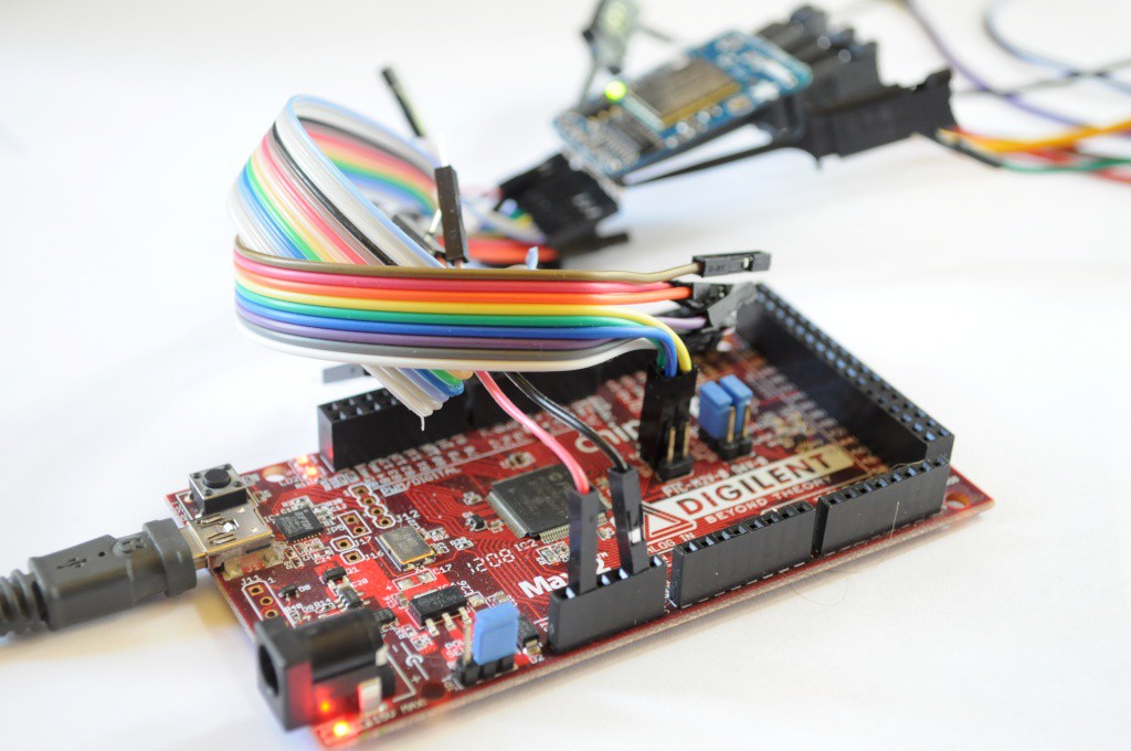
To make a bit of a long story short, I ran into a problem similar to the issue with the capacitive touch sensor requiring the ChipKit I2C library to be updated from the Arduino 0023 libraries to the new Arduino 1.x (post-Due) libraries, to make use of the additional features that have been added in the last few years. With the capacitive touch sensor, it was fairly easy to add the repeated stop condition support from the newer Arduino 1.x I2C/Two-Wire libraries, but the Adafruit CC3000 library is based on the much larger Arduino 1.x ethernet library, so there was a good deal of effort involved -- porting the Adafruit CC3000 library from the AVR/Due to the PIC32 from the top, while simultaneously updating the ChipKit Arduino peripheral libraries from the bottom.
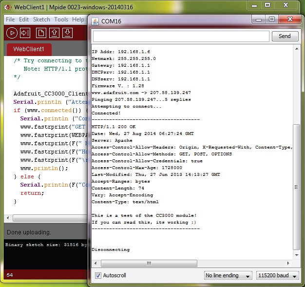
Fully updating the ChipKit libraries to Arduino 1.x would be a full-time task for someone familiar with their inner workings for a good week or two, so it's well beyond the scope of this project -- but after a solid weekend of work I was able to successfully port enough of the Arduino 1.x ethernet library (and its dependencies) to then port the Adafruit CC3000 library to the ChipKit! The picture above shows success, and the Arducorder Mini successfully fetching its first webpage and displaying it over the serial console. Great stuff!
In the end, this means that in order to compile the Arducorer Mini firmware, I'll also have to maintain an updated version of the MPIDE on the github repository. A side effect of this will be that Chipkit folks should be able to enjoy the benefit of some (partial) Arduino 1.x compatibility.
Open Mini Spectrometer
In addition to the WiFi module, the other high-risk high-gain aspect of the Arducorder Mini is creating a new version of the open mini spectrometer suitable for one of the low-profile modular sensor boards. I really needed to build (and not code) last weekend, and have been boring some of my rock-climbing buddies (who are optical physicists) with the idea of making a tiny pinhole spectrometer without any relay optics for a few weeks, so it was time to make a first prototype and see how it would work out.
One of those rock climbing optical physicists (who is much more skilled at climbing than I am) suggested that instead of 3D printing out the spectroscope as I did originally, that the ~0.2mm kerf of the laser cutter at our local hackerspace Xerocraft might yield a reasonably thin slit while being amenable to being built in 2.5D with a sandwich of laser cut pieces, like the Open Source CT Scanner. This is a great idea, so I decided to try it out.
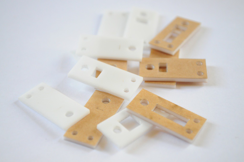
In order to make a low-profile spectrometer that doesn't stick out, the spectroscope (the optical bits of the spectrometer) actually has to live on both sides of the circuit board. There should be about 6mm of clearance on the back of the board (between the sensor board and the motherboard), and about 8mm of clearance on top of the board. I drew a few sketches, and cut out a first test spectroscope that would fit on one the open mini spectrometer boards (for testing) out of some thin 1.5mm plastic that I found in the material bin (pictured above).
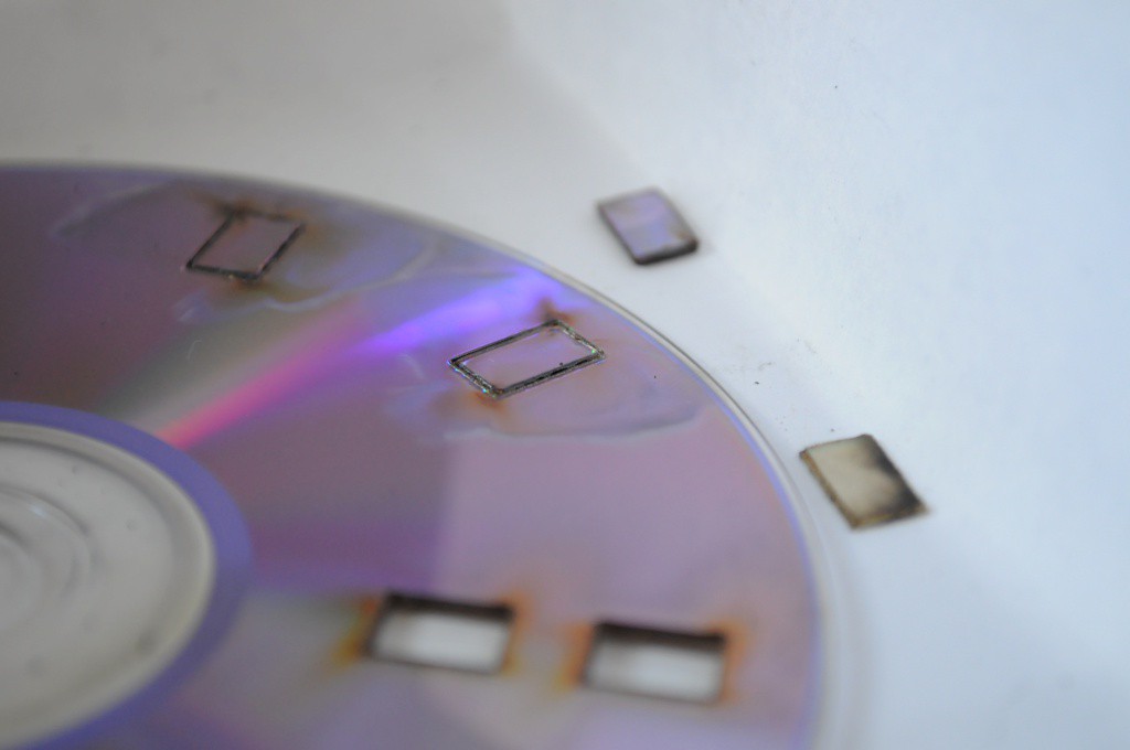
While I used an inexpensive 1000 line/mm transmission diffraction grating sheet for the first open mini spectrometer, I've seen a lot of folks (like PublicLabs.org) get impressive results with much larger spectroscopes built from DVDs used as 1350 line/mm reflection diffraction gratings. I decided to try laser-cutting a section of DVD to precisely fit into the laser-cut acrylic spectroscope sandwich, but it turns out this isn't a fantastic idea -- the tiny DVD-piece gratings end up being covered in residue from the process, or delaminating, or seemingly changing their properties entirely. I tried cutting out about half a dozen, and taking the best to make a solid attempt.
With most optical systems (especially spectrometers, where you're usually light starved and fighting a poor signal-to-noise ratio), it's important to have an absorptive light-tight matte black optical chamber that maximizes the chance that any stray light will get absorbed, and won't bounce around until it hits the detector. Aside from transparent plastic, the glossy white plastic I used here is probably the worst plastic you could build a spectrometer out of, so I spraypainted it flat matte black to reduce the noise.
Unfortunately this first iteration didn't yield a fantastic spectrometer -- likely from a combination of a poor grating with such a tiny chamber where placing baffles to capture the unused diffraction orders from the grating was nearly impossible. I think this means it's back to the transmission grating, and a bunch more iterating!
I'm also looking into off-the-shelf spectral sensors that might be suitable (and please feel encouraged to send in suggestions). While a very inexpensive open mini spectrometer is attractive, I'd be happy to include a more expensive sensor if it were off-the-shelf, fit the size requirements, and was reasonably capable.
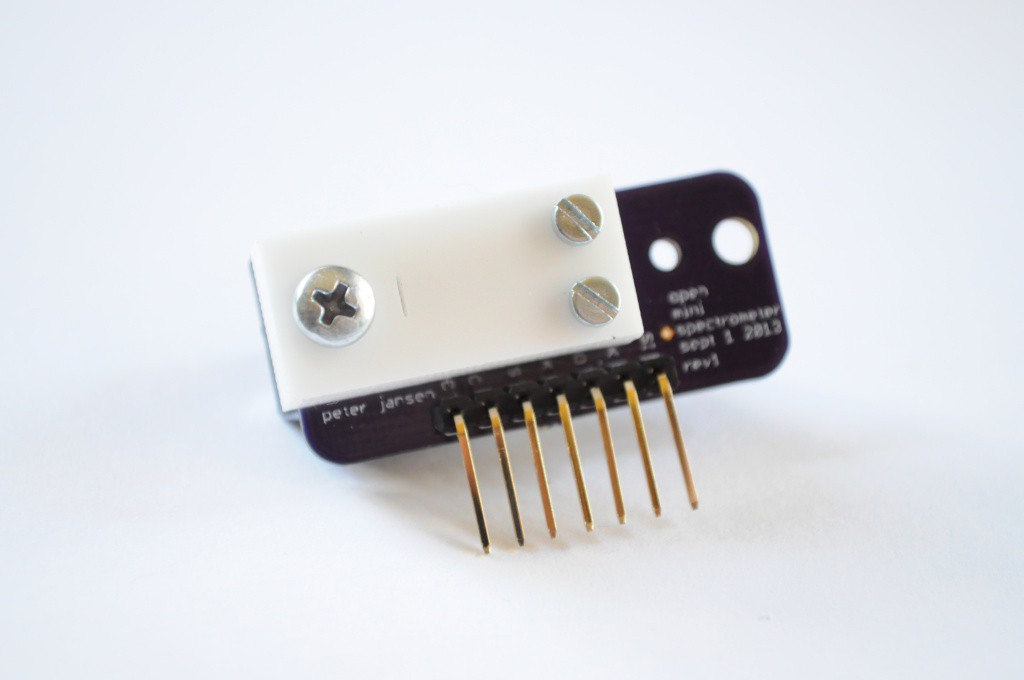
It's important to remember how challenging this spectrometer miniaturization is -- above, the picture shows just how small I'm trying to miniaturize it to. That's tiny! And challenging, but I don't think impossible.
Part Selection
While most of the major components for the prototype Arducorder Mini have been chosen, I thought I'd highlight two cases where the final selection has a few alternatives.
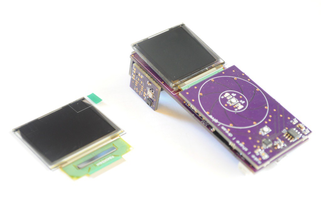
The main display uses a bright, beautiful Organic LED (OLED) display with 16-bit colour, and is about 1.5" diagonal with a 128x128 pixel resolution. When I first started developing the design concept about three months ago I also ordered some slightly larger displays to choose between. At 160x128, these displays offer a little more display real-estate, but with a lead time measured in months I knew this decision would have to wait until these arrived.
I have to confess that in the new months that this project has been active from concept to prototype, I've really fallen in love with the tiny form factor of the Arducorder Mini with it's 1.5" display. It feels very good to hold in ones hand -- not too big, not too small -- and the minimal memory requirements of the 128x128 display keeps things tractable. I remember reading an interview with the Raspberry Pi folks some time ago where they said that if they were constantly chasing new hardware features, they'd have never finished and released their first design. I feel the same here -- I'm not sure that adding a small amount of display area will substantially increase the user experience enough to change a working industrial design, or warrant the risk of using a long lead time part during development. It's also important to me to use parts that are easy for people to source and keep the barrier for entry as low as possible, and these 1.5" OLEDs are an inexpensive easy to source part with an estimated long lifetime, so I think the decision will likely be to continue to use the existing (and great!) display.
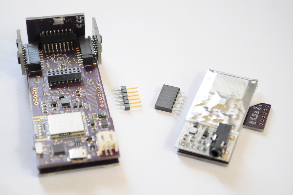
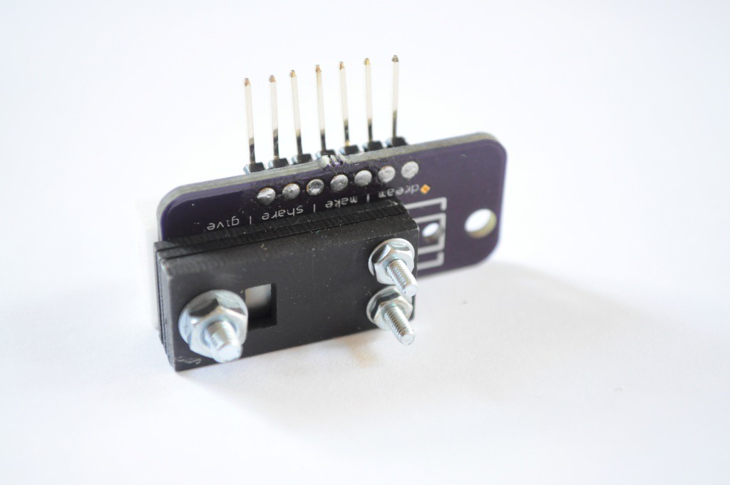
Another part that I'm having a bit of trouble selecting is the connector that goes between the motherboard and the radiation sensor board. I designed this to have a standard 6-pin 0.1" header, but didn't actually select the part before sending off the board, thinking that I'd be able to find a mechanically sturdy polarized locking connector without issue. I had this locking receptacle in mind when I designed the part (the same used for the Olimex ICD2 PIC programmer), but it turns out it's meant to be a board-to-cable connector, and I haven't been able to find a mating end that's board-mount.
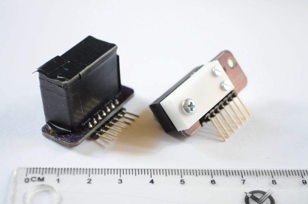
Above is an alternative, which makes me mechanically a little nervous for this application because it doesn't have a lock to ensure that the two halves don't come unconnected, but seems to have a very good connection. Unfortunately the pins are looped and a little too big for the holes on the PCB, so this one's out too. I feel like I've looked at literally thousands of connectors and haven't found one yet, but hopefully I'll strike gold and find a suitable locking 10-12mm stacking height connector shortly.
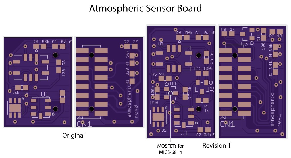
Atmospheric Sensor Board Revision 1
Last but not least, I also put together the first revision of the atmospheric sensor board, and sent it off to OSHPark. This version adds 3 MOSFETs for the heaters on the MiCS-6814 gas sensor, which require more current than the PIC32 pins can handle.
Now that the WiFi module is working and much of the hardware seems to be in a good place (or moving towards minor revisions), I'm going to try and design a first iteration of the spectrometer sensor board to send off by the end of the week, and then start working on the user interface concept and implementing the beginnings of the graphical user interface!
Thanks for reading, and stay tuned!
Discussions
Become a Hackaday.io Member
Create an account to leave a comment. Already have an account? Log In.
Hi, where can I buy Open Mini Spectrometer module with case?
Best regards,Vito
Are you sure? yes | no
Are you sure? yes | no