Close
0%
0%

Cheap and Easy to Build 3D Printer

A budget 3D printer that is easy to build with basic tools. A closed loop system using optical mice is to be used for greater accuracy.

Similar projects worth following
I have long dreamt building my own 3D printer on the cheap, but the idea of using linear actuators always scared me of doing so. First of all they are expensive, and secondly great care needs to be taken during construction to have good accuracy in the end due to the open loop nature of traditional implementation.

I eventually realized that moving a plane is not that hard without using any linear actuators. You can basically take an holonomic drive system from a robot to do so. In sum, is like having an robot turned upside down and fixed to the ground, and having a work plane above it. Since the robot is fixed, when the wheels turn the work plane moves instead.

The main problem with this approach is the accuracy of moving the work plane since my idea is to use either servos or DC motors. To compensate for that the plan is to use optical mice (more than one for accuracy) to correct the movement of the work plane. The Z axis should use a similar approach, but with a simple wheel.

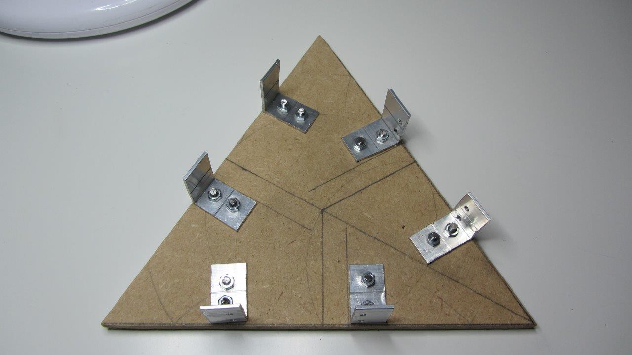
The main idea behind this project is that it should be easy to build, and quite forgiving in the actual placement of components. Most of the complexity will be in the software to compensate for the less than ideal physical construction.

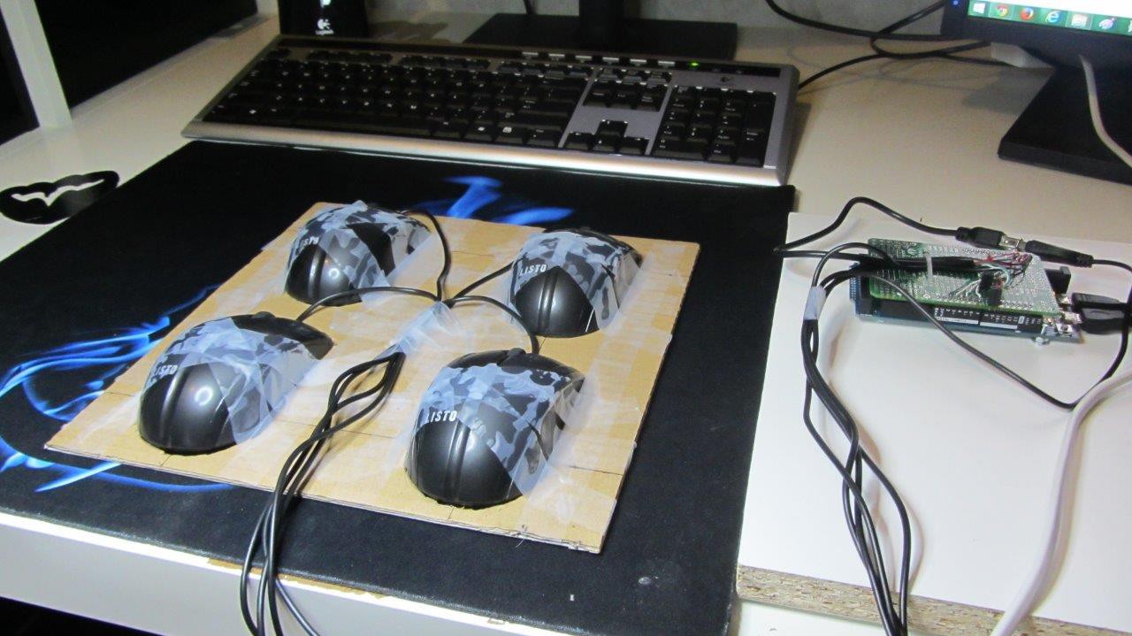
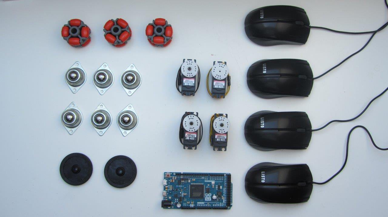
I am planning to leverage on some publications where optical mice were used to provide odometry, which was used mainly in robots, but this 3D printer is basically a robot turned upside down. :-)

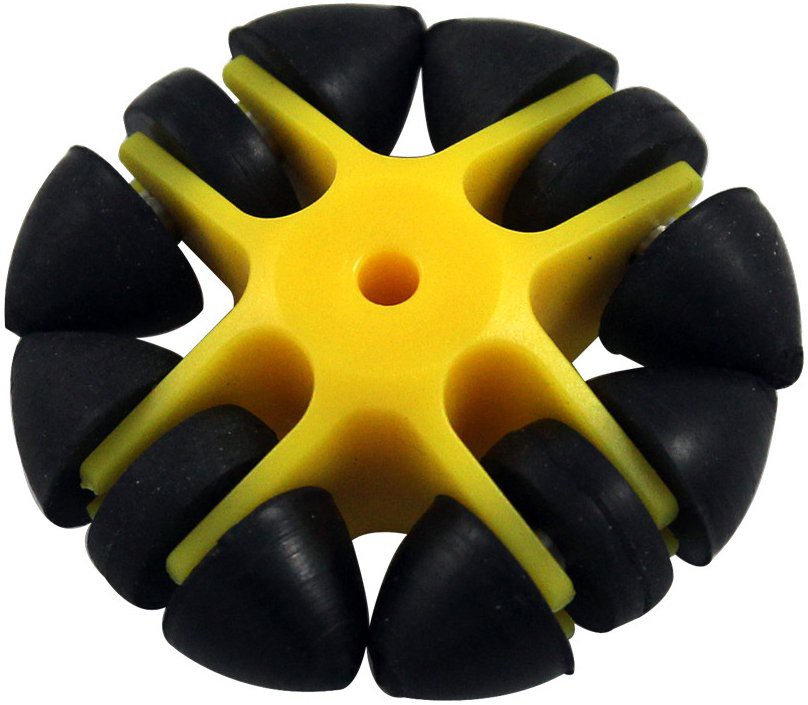
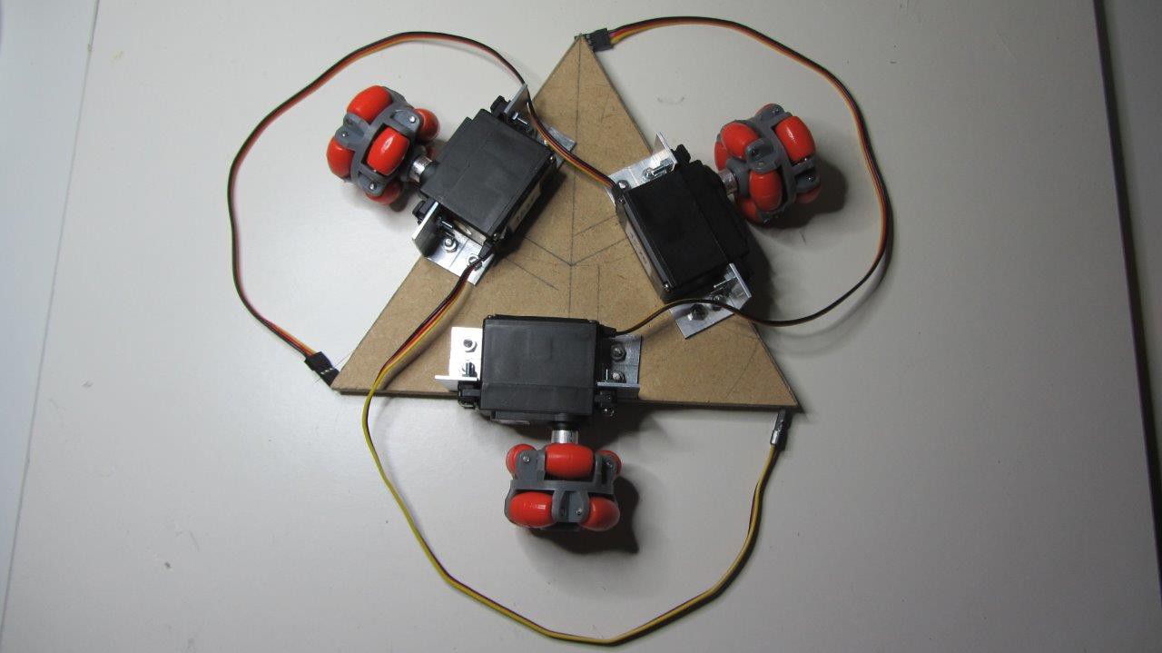
The holonomic drive has an extra degree of freedom (i.e. rotation) that might be interesting to explore, if it proves to be an advantage. 

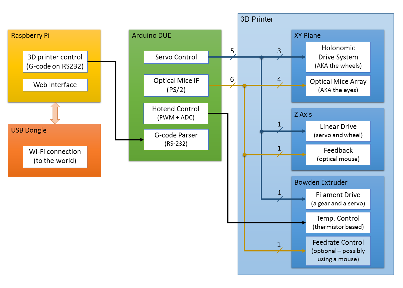
For the first prototype at least, my idea is to use an Arduino Due to parse the G-Code directly, and translate it to the physical movements of the 3D printer, handling all the real time stuff. The Due was chosen as I expect to be doing a lot of trigonometry, and I believe that using an 8 biter would pose an extra challenge since my time is heavily constrained (I can always try to optimize things later if time allows).

Then to make it standalone I plan to use an Raspberry Pi to host a web server through Wi-Fi so we can submit prints or otherwise control the printer using a tablet or smartphone for instance.

The following system diagram tries to better illustrate what was just described.

Truth be told I am not a software guy and I like to program mostly low level stuff (e.g. driving the hardware), so I'll try to offload the GUI portion to some already created open source project if possible. The OctoPrint project (http://octoprint.org/) seems to be a great candidate so I'll try to have my interface compatible with it (if I just keep it RepRap compatible, I believe it should be enough).

As the complete project will be fully open source anyone can improve on my shortcomings as they see fit. I am releasing all the code that I am developing under the MIT license.

Independently of the end result of this sort of experiment I hope to have at the end a few libraries that could be useful to other projects as well, namely for creating (3D printing) robots using holonomic drive systems, and optical mice as feedback... ;-)

A short video explanation of this project can be found at:

  • 3 × Dagu Omni Wheel - 40mm Omnidirectional wheel
  • 4 × HS-422 Servo Motor Hitec Standard Deluxe Servo
  • 1 × HS-645MG Servo Motor Hitec Ultra Torque Servo for the extruder
  • 1 × Hotend MK7 0.4 mm nozzle for 1.75 mm filament
  • 1 × Extrusion drive gear 12 mm OD, and 5 mm ID

View all 14 components

  • The Slippery Wheels Conundrum

    Sugapes08/19/2014 at 21:47 1 comment

    As soon as I got back from my trip I started working right away on the question of the slippery omni wheels not gripping very well to the XY plane, due to the plastic rollers. I was already expecting this to be an issue, I was just hoping for it to be more easily solved.

    The first idea that I had was to try to increase the friction by addressing the XY plane itself, which is just some sort of light wood board for now. I tried several different strategies some of those showed only very limited success (i.e. some improvement, but hardly enough). Some of the main ones were: to simply use a melamine coated wood board which naturally has a rough side; to glue some anti slip mat (used to line drawers) to a wood board; to spray some rubber based paint on a wood board. (Picture below).

    Right from the start I did notice that the wheels do seem to grip (a bit too) well to the neoprene side of my mouse pad, so in light of the limited success of my previous attempts, I decided to order some neoprene fabric (which is not so cheap), and to try that one next.

    Another possibility to address the issue at hand is to select different omni wheels. There are some very nice ones out there on the market but usually they come with a heavy price tag. I did find some alternative wheels with rubber rollers, and a somewhat different configuration that are still at an acceptable price (less that 6 euros per wheel, about the same price as the ones I am currently using), so I should be trying those next.

    Low cost of the final product is an important goal of this project, that is why I always try first the cheaper alternatives, and not necessarily the ones that look more promising. It would certainly be cheaper for me if I invested directly on the solutions that I figure had the most chances of working on the first try, but instead I find myself spending a bit more trying to figure out the cheapest option available. However my engineering mind does get a kick out of this extra challenge.

    Yet another alternative that I am now considering is to build some sort of DIY omni wheel lookalike. This idea was suggested by some Hackaday readers on the comments section (of the blog) when my project made the front page (Yey!). I had several nice suggestions there, but I wish to send special thanks to [jimmy_pop], and [RunnerPack] for the very helpful hints that got me on this track. The main idea here is to use a couple of rubber balls on axes placed 90 degrees apart which should work similarly to an omni wheel (but much easier to build). I believe these are called Killough wheels, and an example can be found at:

    http://www.cs.hmc.edu/~dodds/projects/RobS01/Assignment4/holo.htm

    I have a couple different ideas revolving around these kinds of wheels, and at least in my mind they look really great, but I worry that with only basic tools, and limited build skills the end result might not be that impressive.

    I am really hoping to get it working with standard (but cheap) omni wheels, but even so I wish to explore this other alternative (i.e. DIY wheels) to have another option for very tight budgets.

    My main drive to have an hardware that works consistently from the start is that I am developing the firmware on an Arduino. We all know this platform is not the easiest to debug, so my best strategy to work with it is to take "baby steps". I mean, I wan't to have something that works right away, and build up the complexity incrementally. The idea here is to write just a few lines at a time, and keep testing it frequently to catch the bugs early thus easing the debugging requirements.

  • It (almost) looks like a 3D printer...

    Sugapes07/21/2014 at 22:15 0 comments

    In the last few days I finished the basic skeleton of my 3D printer, and now it almost looks like one!

    The darn thing came out bigger than I imagined though! I was aiming for a build volume of around 30x30x30 cm, and I gave enough margin to achieve it, so in the end my "desktop" printer no longer fits on my desktop! Well my desktop is kind of small anyway...

    However in this first iteration I might not even reach those marks. First of all the aluminium support you can see above the XY drive system is limiting the Y axis travel to around 20 cm or so, and the drawer slider I am using for the Z axis is actually limited to 27 cm when fully extended. Those are the maximum values, but the main limitation is still the XY surface that I am yet to find the best candidate for. Due to the way things are setup the full XY surface would need to be around 60x50cm, (for a 30x20cm build surface), it also needs to be pretty flat and not to heavy, and additionally allow the omni wheels to grip well. To make a long story short, It has been tough to find a material that fits all those three constraints (and yet while not being too expensive). I was aiming for some sort of melamine tray, but they don't seem come in those big dimensions, so the search continues.

    This is how it would look with a (too short of) XY surface. Unfortunately the MDF leftovers I had lying around aren't big enough to give it just a trial run.

    The next picture gives a closer look of the XY drive system. The main idea is for the wheels to push the XY surface against a rigid structure. This has two main purposes. One is since the XY plane is much bigger that the distance between the wheels the aluminium structure above prevents it from tipping over. The other reason is to prevent Z axis oscillations due to the unevenness of the omni wheels. To that effect the holonomic drive system is mounted on a suspension that pushes the XY plane against the big aluminium square above it (it has 3 caster balls that can barely be seen in the picture bellow).

    The shape of the XY support structure is not the ideal one to allow the full extent of the Y axis, but it was the easiest to build. I'll stick with it for the time being for my initial testing, and replace it later on with something more sturdy and which does not limit the Y axis travel (to let it have the full 30 cm range instead of the current 20cm).

    Unfortunately I will not be able to work on the hardware part of this project for the next few weeks as I will be traveling on vacation with my family. I'll try work (in the evenings) on the code, and on the documentation, so it won't be a complete halt.

  • It has eyes!

    Sugapes07/17/2014 at 07:29 0 comments

    Things are moving slowly but at a steady pace, but between a very demanding job, and actually spending some time with my family it is hard to do any better. However any free time that I can get hold of, is to advance this project.

    This is my latest achievement, and I finally completed the principal part of the XY plane movement. You can recognize the holonomic drive system in the middle, and an array of 4 mice around it, in an (almost) perfect square.

    Everything is standing on screws for easy adjustment. This is crucial, since the focus on the mouse optics is very narrow (just a couple of millimeters), and they need to be adjusted to be very close to the surface of the XY plane (bottom side).

    Things are not as compact as I would wish but since time is very short, I am aiming for an easier build rather than the most efficient prototype. The main disadvantage is that the XY plane will need to be much larger that the actual build surface. This is due to the fact that it has to be over the wheels and mice all of the time, for every point that can be reached by the print head. In sum I need right now an extra 10 cm around the usable work area.

    Also since the XY plane will be much bigger that the area defined by the wheels I need some kind of support for it not to tip over. I still have to build this support to start testing the performance of my drive system with optical feedback.

  • Found memories of my youth...

    Sugapes07/07/2014 at 23:37 0 comments

    I woke up last Sunday morning needing to draw 120 degrees angles, so I embarked on a quest to find a protractor around my house. Of course none could be found. I even went through my kids school stuff but apparently a protractor is not part of the required school material for 8 year olds... Go figure!

    Then a faint recollection of my youth popped into my mind of me splitting a circle into 6 parts  (almost the same!) on the school's black board using a giant compass and ruler... We sure did know how to have fun back then!

    I was filled with joy because a compass is actually part of my hacking tools (but not a protractor) so I created the beautiful peace of art below that would serve as the basis for my holonomic drive system.

    A quick break for some STEM outreach: For any young hackers possibly reading this, please do pay attention to those geometry classes... It might actually save you a perfect  hacking (Sun)day in the future!

    The other big advantage of having a very limited tool set to work with, is that you also get a very nice workout with all that manual sawing that needs to be done. Working on the metal parts is where you burn the most calories. Who said hacking is a sedentary activity? (Probably no one!)

    At the  end this is what I had to show off. I am specially proud of those crooked edges, but that is what you get when you saw things literally over the knee. This is just to show how not to do things, clamping things down when sawing really makes it easier (as I recall it from my youth as well). A vice is already in the shopping list however!

    In the end it didn't turn out too bad... Luckily the screw holes had a little play, so I could compensate a little the small(ish) imperfections of the build. The servos ended up attached to the board rock solid, and the shafts seem to be in the correct alignment as well. 

    The moral of the story: pay attention of the errors you are introducing along the way, then to compensate them just create more errors in the opposite direction. In the end it might turn out OK!

    That's it for the time being. At least now I can get things moving (pun intended)!

  • Testing Accuracy

    Sugapes06/28/2014 at 23:10 0 comments

    The crux of this project is of course what kind of accuracy to expect from the mouse readings, so I have been doing a lot of experimentation to try and figure out what to expect.

    Unfortunately even with all the trials I did so far I cannot yet tell for sure that I can get enough accuracy/repeatability to be of any use for a 3D printer. On ideal conditions, for instance with slow movements, and on a good surface, it seems that the results I am getting are much more consistent. But as soon as the movements are a bit more erratic, and with enough acceleration, then errors start building up quite quickly.

    Strangely enough I get somewhat less error accumulation when the mice are connected to the PC  than when they are connected to the Arduino DUE. I might still have some issue in the PS/2 communication that is making matters worse, so next step is actually checking that my method of reading data from the mice is sound. Of course that on the PC side I had to turn off the mouse acceleration (with a known registry hack) to have meaningful readings in Windows.

    From the start I didn't expect this to be easy, and my plan to mitigate the errors accumulating included using several mice, and take advantage of the geometric relations among them to figure out where the errors are. That is why you can see the weird contraption below with several mice scotched to a piece of cardboard. In this particular configuration all the readings on all the mice should be the same (if we exclude movements with rotations), but the reality is that after a while they start to diverge. One simple idea for an error reduction algorithm in this case, would be to take the max value of all the readings, being that it is probably the most correct one. The reason behind it is that due to the way an optical mouse works, it is reasonable to assume that it should not over report a displacement.

    I guess that I still have a lot of research to do on how to adequately mitigate the errors I am seeing, and I hope that there is a solution waiting to be found. In any case I am starting to see that my chances to having something ready before the THP contest deadline are slim to none, but that was just the excuse to get me started.

    Truth be told, this question of using optical mice for closed loop robots/whatever has been scratching my mind for quite a while now, and now that I am on it, I feel that I cannot be stopped!

    I have this gut feeling that this should be possible, just don't have yet the full solution for all the problems.

  • Parcel at my door!

    Sugapes06/21/2014 at 20:58 0 comments

    Wow, this was super fast. I just ordered this stuff three days ago (late in the evening), and this morning the postman was knocking on my door with a parcel in his hands... Could not believe it!

    Now I can start prototyping. Time to roll up the sleeves and get to work.

    I have to say that I am a bit disappointed with the omni wheels, the plastic rollers don't seem to exert a lot of traction. Luckily I can fully control the surface that they will be adhering to. But it also needs to be good for the optical sensor in the mice.

View all 6 project logs

Enjoy this project?

Share

Discussions

natevplas wrote 06/26/2020 at 14:51 point

Not sure if you're still pursuing this idea as 3D printer prices fall, but it sparked an idea in my head that you could use a similar system for a robot vacuum.  I guess the holonomic drive might be unnecessary, but the mice as navigation could be really interesting!  It would be exceptionally cool if it was an agnostic platform that you could place your existing vacuum on, plug in the hose, and it drives around your house!

  Are you sure? yes | no

George I Fomitchev wrote 08/15/2016 at 06:36 point

would be interesting to put our 445 nm 2.1W and 3.5W lasers ... if someone would like (just search Endurance lasers in google

  Are you sure? yes | no

Dashack wrote 06/28/2016 at 12:10 point

what happened to completion ?

  Are you sure? yes | no

nikhil255176 wrote 08/10/2015 at 19:16 point

can i get a full detailed information on this project?? with the coding as well...

  Are you sure? yes | no

Duane Degn wrote 02/03/2015 at 23:37 point

I haven't tried the Dagu omni wheels but I've used Vex omni wheels and IMO, they're very nice.

Here's a link to there 2.75" wheels:

http://www.vexrobotics.com/vex/products/accessories/motion/276-1902.html

They also have 4" wheels:

http://www.vexrobotics.com/vex/products/accessories/motion/276-2185.html

And just now I learned they have 3.25" wheels:

http://www.vexrobotics.com/vex/products/accessories/motion/276-3526.html

I haven't used the 3.25" ones but I've used the other two sizes and I think they're great.

The rollers on the Vex omni wheels are a green rubber. Perhaps the Vex wheels wouldn't slip as much as the ones you're using.

  Are you sure? yes | no

HyGy wrote 08/05/2014 at 13:40 point
I do not see in the description why do you turn it upside down? Don't you think it can be work like a normal robot? Then you need smaller working area, couse the robot moving on the area, not the area on the robot.
If you mount the motors with 2 box profile inside (which slide in each other), you can change the distance of the motors from the center point, and you can print bigger things. What do you think?

  Are you sure? yes | no

Sugapes wrote 08/08/2014 at 12:10 point
Thanks for the comment! The reason to turn the robot upside down is to have something that resembles more to desktop 3D printer for a first prototype. I imagined it would be an easier endeavor like that. Eventually in the future I would also like to try something resembling what you are suggesting. Even if I end up with a final accuracy for this 3D printer not as good as a more orthodox one, I believe the main strength of this approach is to actually scale it up to print larger objects. For that the robot would need to stand upright once again, but another set of challenges would need to be addressed then. For instance the robot might need to carry everything around, including electronics and power supply, which makes it heavier, and harder to build. I am also expecting that controlling for wheel slippage, and optical surface tracking to be more difficult in this later case. To sum it up, with this project I hope to develop the technologies necessary for more ambitious ones, so one way to look at is is more of a proof of concept of the techniques used.

  Are you sure? yes | no

zakqwy wrote 07/14/2014 at 18:14 point
Do you foresee any issues using omni-wheels for the base? In my experience they tend to ride a bit bumpy; even if it's not much, any Z-axis jitter will affect your layer resolution. Does the platform seem pretty smooth when you move it around?

  Are you sure? yes | no

Sugapes wrote 07/15/2014 at 07:27 point
Yes, they are a bit bumpy, and the ones I am using right now seem a bit more bumpy than I anticipated. However my idea is to have some rigid support above the work plane, and have the drive system push against it with some suspension... Hopefully it will mitigate the bumpiness of the wheels, but I am also considering new wheels for my project, since the current ones are very irregular, and don't grip very well even on a rubbery surface.

  Are you sure? yes | no

zakqwy wrote 07/15/2014 at 12:16 point
Makes sense. Maybe some kind of Mecanum wheel?

  Are you sure? yes | no

Sugapes wrote 07/17/2014 at 07:38 point
I know that there are much better wheels out there, I just chose the cheapest ones I could find, and I was expecting some issues due to it. In any case, I'll try to do my best with them, and then if I see they are severely limiting the performance of my 3D printer I'll replace them with better (more expensive) ones. Thanks a lot for your interest!

  Are you sure? yes | no

Tushar wrote 07/05/2014 at 16:14 point
Innovative idea! Can't wait to see how it turns out.

  Are you sure? yes | no

Sugapes wrote 07/08/2014 at 00:11 point
Thanks! I can't wait to see how it turns out too... :-)

  Are you sure? yes | no

sad_ken wrote 07/04/2014 at 10:45 point
Excellent project, can't wait to see how it turns out.
Have you tried running the mice over various printed patterns to give you higher accuracy? Some optical trackballs use a random dot pattern over the ball to increase accuracy.

  Are you sure? yes | no

Sugapes wrote 07/08/2014 at 00:11 point
Thanks! I haven't yet tried different patterns, but part of my contingency plan to improve the mice tracking is indeed using different materials with different textures, and possibly different patterns. Another idea is to try to improve on the mice optics by modifying the light source (more LED), and/or change to better lenses.

  Are you sure? yes | no

jacksonliam wrote 07/03/2014 at 20:24 point
OctoPrint would the the Web interface you're looking for if you stick to G-Code like all the other 3D printers!

I really like this idea. Perhaps different mice would yeild better results?

  Are you sure? yes | no

Sugapes wrote 07/04/2014 at 07:21 point
Thanks for the support!
I did try a few different mice, including a 60 euros gaming mouse (which I would never use on this project, but just for kicks), and the later did seem to have quite nice repeatability for steady and slow movements. But even the gaming mouse started to show cumulative errors for more random movements.

  Are you sure? yes | no

Sugapes wrote 07/04/2014 at 07:28 point
About the G-Code, the Arduino Due will parse standard G-Code over the serial interface (same commands as the RepRaps), and the web interface (running on the RPi) should be pretty simple at the beginning, letting you to choose a file and forwarding it to the Arduino Due. This is just if you want it stand alone, otherwise you can simply connect it to the PC and send the file over the serial interface (the RPi is in fact optional).

  Are you sure? yes | no

Sugapes wrote 07/10/2014 at 07:38 point
I just gave another (more careful) look to OctoPrint, and it really looks exactly what I was looking for. Somehow the last time I looked at it, I missed the fact that it is open source, and ready to run on an RPi. I'll definitely try to keep my interface compatible with this great software, and all of a sudden an important chunk this project is already done for me (but not by me). That is the real power of open source!!! Thanks for the tip jacksonliam (even if it took me a while to fully digest it :-) )

  Are you sure? yes | no

jacksonliam wrote 07/10/2014 at 08:03 point
Yeah octoprint is really great! There's a lot of software out there for standard 3D printers so it is useful to remain compatible with that interface! Most repraps seem to use the marlin firmware (or fork of) so I guess your firmware will be similar. I assume you're using a standard slicer (like slic3r or cura)?

  Are you sure? yes | no

Adam Fabio wrote 06/29/2014 at 03:12 point
Hey Sugapes, that's quite an unorthox printing platform you have there! I'm hoping you'll get some good results from it. No one ever said all 3D printers have to be high resolution - even if your resolution is lower, you'll still be able to make a lot of useful prints with it.
Thanks for entering The Hackaday Prize.
Try to upload some more documentation from your project as you move ahead!

  Are you sure? yes | no

Sugapes wrote 06/30/2014 at 07:34 point
Thanks! That is why I am planning to move ahead even if I cannot get the desired precision from my experiments. Just to see what kind of stuff I might be able to print with it! DeadBot Mk 1 (how I nicknamed it) should be pretty crude but it will mainly serve as a learning platform, and hopefully it will be the first of a series with ever increasing precision.

  Are you sure? yes | no

DeepSOIC wrote 06/21/2014 at 22:00 point
Don't you think that optical mice are not accurate enough? I forsee a problem that after a few repeated moves back and forth (a 3d-printer does this all the time), an error will accumulate and origin will be lost. Maybe a camera at the bottom to track the positions of some marks to correct accumulated errors periodically?
Fun idea by the way.

  Are you sure? yes | no

Sugapes wrote 06/21/2014 at 22:24 point
Yes, you're are right, but I guess that is the whole point for this "experiment"... To see if it is possible at all to use optical mice for feedback. I have been considering this technique for quite a while for a drawing robot, but to enter the THP contest I thought that a low cost 3D printer would have more flair. I am probably being overly ambitious but I expect that at the very least to have a capable drawing bot in the end, if it turns out that the accuracy is not enough for a 3D printer (just turn the damn thing back on its feet and let it do what it was really meant to do)!

  Are you sure? yes | no

DeepSOIC wrote 06/21/2014 at 22:54 point
Maybe of interest: there are optical encoders commonly used in regular 2D inkjet printers that consist of an optical module and a transparent plastic strip with fine line pattern on it. AEDS-9621 for example. They won't accumulate error.
Looks like they won't do for your rotatable table, but anyway may be worth looking at.

  Are you sure? yes | no

Sugapes wrote 06/22/2014 at 21:15 point
The problem I see with those is that the table is moving all over the place so I wouldn't know where to stick the patterns for the optical encoders to track. In the next few days I am starting some experiments with the optical mice to see what kind of precision I can really get. I'll post a log entry as soon as I have some results to share.

  Are you sure? yes | no

DeepSOIC wrote 06/22/2014 at 22:28 point
good luck! It will be cool if the precision turns out being outstanding!

  Are you sure? yes | no

Sugapes wrote 06/20/2014 at 09:57 point
I am sorry I don't have much to show at this time but my inspiration came just in the last few days. I already ordered some material to start prototyping but I am still waiting for it.

If this seems a bit rushed is because it really is. I just realized that the community vote deadline was coming by (with quite a whooshing noise) and I did't want to miss some early feedback (and some score points as well :-) ).

Hopefully I will have something to show soon but until then you just have to use your imagination... :-)

  Are you sure? yes | no

Similar Projects

Does this project spark your interest?

Become a member to follow this project and never miss any updates