So recently I've been focused on BicycleCompanion, which I also submitted to HackadayPrize, since as I mentioned in last log I hit a bump with current design based on NRF51822. I still have no idea why I couldn't get Bluetooth to work but having only 16KB of RAM makes me wonder if it would work at all.
Anyways, yesterday I woke up to a first good news: I received another very kind donation on KoFi from someone interested in seeing thumbmouse move forward. After considering what I should do with the funds I realized the best would be to buy both an evaluation board and a module for a newer Nordic chip. This way, I could properly test any code before I finalize the PCB design. Then, I would already have a proper module for the PCB. I first try to see which Nordic chip to aim for. While I think nrf52840 is a very good option, I couldn't find BLE module for it with castellated pads from a respectable source. Since I already had a bad experience with the other module due to this, this was a must. In the end I decided to go with nrf52832, which is mostly similar. I found that Seeedstudio had some nice cheap options for both evaluation board and module. I decided to buy:
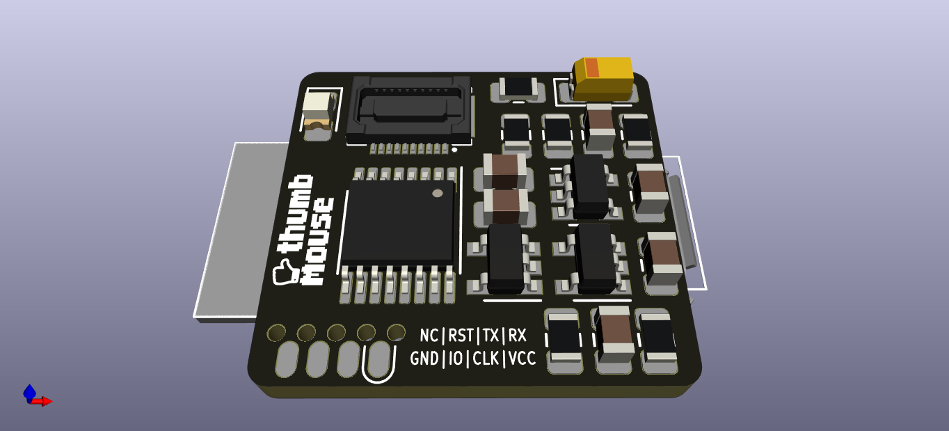
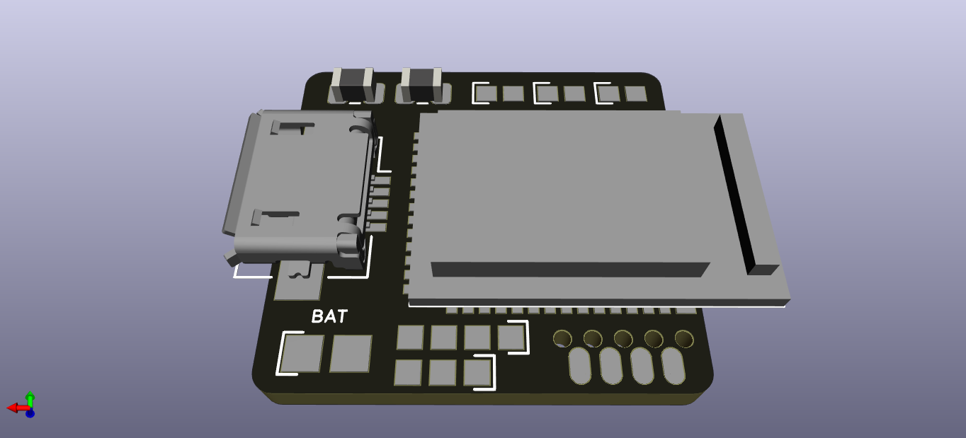
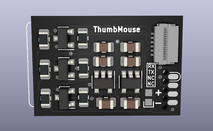
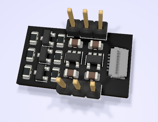
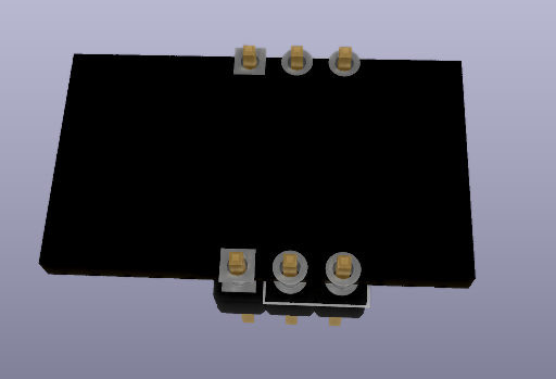
So, after ordering I decided to start revising the design I had, based on the SPI based BlackBerry trackpad series, to include this module. So far I have a reasonable layout of components without increasing the size too much, although I haven't put down traces yet. Right now the board looks something like this:
The main changes are:
20-pin FPC connector for 8250 series of trackpads (actually, I suspect many other models have the same pinout, will have to check)
Battery Charger IC, to charge via
Micro USB port
Voltage level translation IC: since I have many lines to translate between 3.3v and 2.8v I had to use this chip
Various pads exposing I/Os, VCC and GND for easy connection of switches, mouse wheel encoder or whatever one wants to add (someone mentioned a trackpoint, for example)
18.8 x 17.3 mm in size (22.2 x 17.3 mm including the protruding BLE module). This is almost the same in length as rev1 but about 3mm wider. I think it is still small enough to be usable.
And while taking a break from revising the design, I saw by chance that thubmouse was featured on hackaday! Really cool, aready got some feedback from there.
The next step will probably be to buy some trackpads to check their size and see what is the best orientation for the connector. Anyways, as I have used cheap post por the Seeedstudio purchase, it may take about 30 days for stuff to arrive. So, I will probably have to wait for that to continue. My plan will probably be to again use Zephyr to have a quick test and then finalize the design. However, I'm considering working on adding Bluetooth handling on NuttX for the nRF52832, and base the code on that. That will take some time though, but I think it would be cool to do. However, once I have the design ready I can already order and test again with Zephyr. So expect this to be done not long after I receive these boards.
Last tests of thumbmouse were made using the board as a breakout for the sensor: the BLE module was not soldered and I connected the PCB via flying wires to an external Nucleo board (as you can see in last post's video).
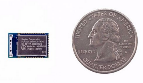
After this test, the next step was to solder the BLE module. This was quite a difficult thing since the BLE module has the pads only at the bottom and not to the sides. Also, this thing is damn TINY. I think for this module it would have been better to use solder paste and a stencil but I didn't want to spend too much for this board at this point.
So, I soldered the BLE module using the iron and I started getting bridges below which were really difficult to correct. Eventually I accepted that I had to use hot air to try to remove it. This took me long time since the module sucked a lot of heat. Eventually I managed to remove it but I ripped a pad of my PCB in the process. So, know I needed to populate the tiny PCB for the third time! Also, I didn't know if I cooked the module in the process or not.
First tests
After soldering the third board (this time it went much better and faster, at least it was good practice), I tried to do a little test with Zephyr RTOS (which I never used before, as I'm used to NuttX). It took me some time to adapt a similar board based also on NRF51822 but eventually I managed to control the LED. However, it was a blink example and the LED would not turn off. I started debugging and found that the board hung when going to sleep between LED turning on and off. This was really strange and after many hours of debugging, since I didn't know for sure this wasn't due to the module being ruined by the heat, I managed to get a blinky test using platformio, which uses the mBed framework. Surpisingly, the LED blinked. Debugging the code, I could see that it used the same RTC1 peripheral to control the sleep(). So, something must be wrong on Zephyr. This led to another set of long debugging hours, e-mailing Zephyr devs, opening an issue, etc. Then, for some reason I remembered seeing some errata documents from Nordic and decided to check if there wasn't actually a bug in the silicon which affected this module (but not other more popular ones which were working on Zephyr). To my surprise, there was indeed a BIG bug, whereas if you didn't set some magic value to some magic address NO PERIPHERALS WOULD TURN ON. I went back to mBed code and indeed this magic code was there. So, I transplanted the code to Zephyr and finally the damn LED blinked!
The bad thing is that even now that this was working, no Bluetooth examples seemed to work (I can't see the advertisements on my phone). Again, I'm sure it is not a hardware failure since the original firmware from Nordic is working and I can see it from my phone. So, I'm guessing there are other bugs affecting this chip or at least Zephyr has some problem with this model. Since I don't really understand much about low-level Bluetooth radio handling, I feel this is a bit out of my reach now. Moreover, I'm starting to feel that it was not a good choice to use this module (considering also the 16KB of SRAM it has).
What now?
So, unless Zephyr devs manage to point me in the right direction for this bug, I think I will most likely have to focus on a second revision of the hardware (which I already started to use the other trackpad series, include battery charging IC, regulator, etc), but this time using a newer module, based on NRF52 series and with easy to solder leads.
However, I would need some help funding this second revision so if you're interested in making this happen, you can help by donating here: https://ko-fi.com/protobits
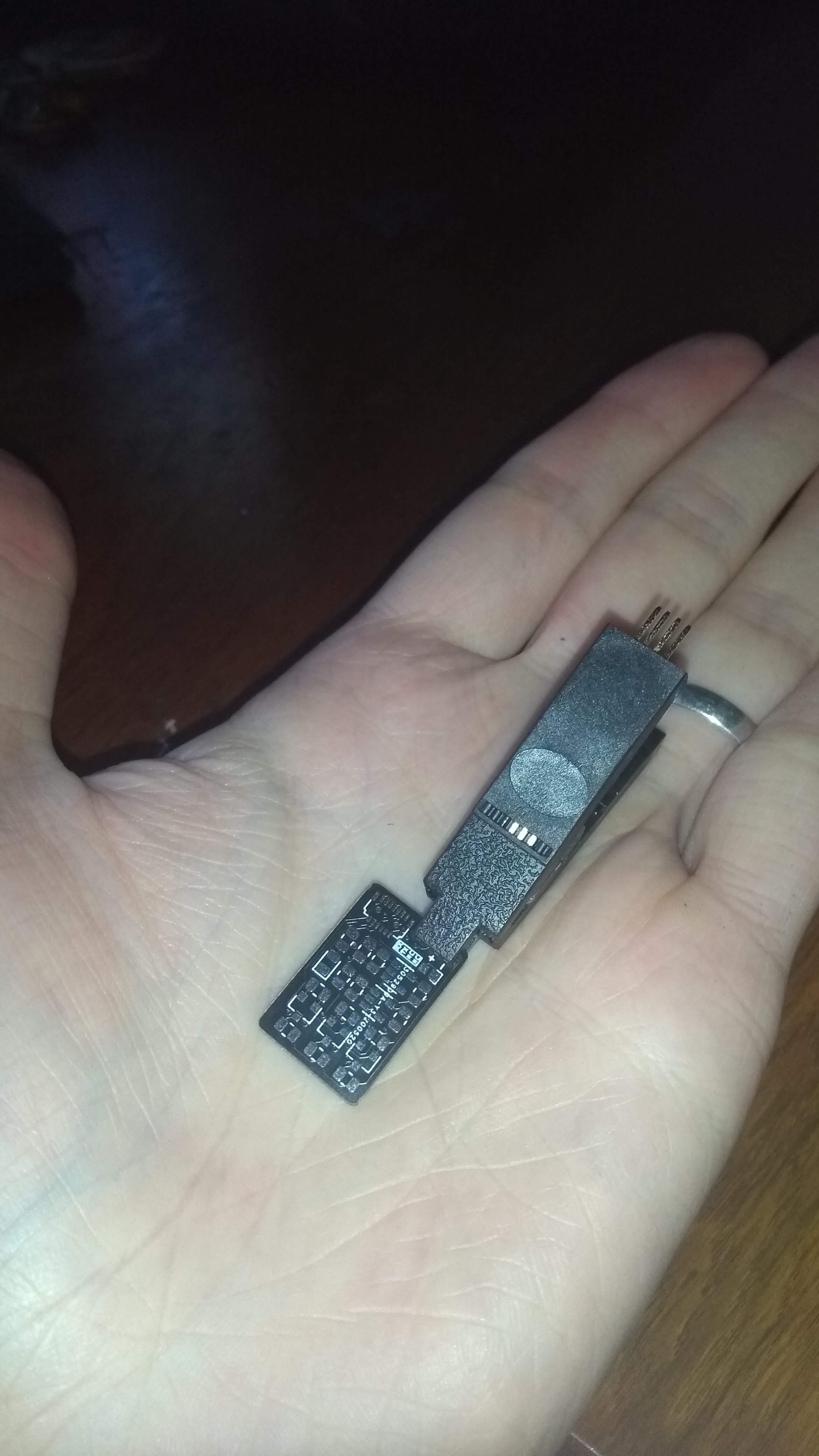
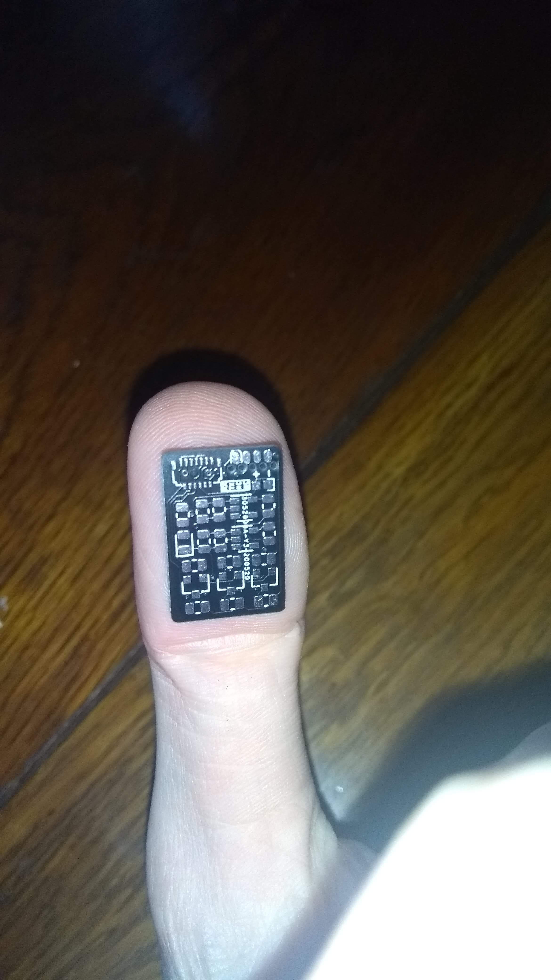
Today I finally received the PCBs (DHL took them for a trip to the other side of town for a few days). I knew it would be tiny but I was really impressed with how small it was. The text indicating the SOICbite pinout was even unreadable.
In fact, I had to test if it was correct to call it "thumbmouse". It seems it is.
While I was still waiting for the batch of passives I ordered, since I had some resistors and capacitors of acceptable values I decided to go ahead and solder this. I still don't have the BLE module (it is sleeping in some post office storage building for some days now), I figured it would be best to first try and test this via an external MCU, since I would not want to solder the BLE module to a useless board since it was a bit expensive.
I decided to use solder paste for this, since it would be good practice and also the FPC connector had a really small pitch and not so accessible pins. The solder paste I bough seems to be a bit dry (it may be since it is a bit cold here and it may require higher ambient temperature, or it is also possible it was not stored correctly). It was quite tough to apply the paste since it would not stick to the pads, so this was a bit messy. I placed all components and used hot air gun to melt the paste. This worked more or less OK, although I melted the plastic base of the microscope and the PCB got stuck. When I tried to take the PCB off the base I messed up and moved a lot of components. So, I had to manually fix everything with the iron and fix a few shorts. In the end it seems to work: 2v8 and 1v8 voltages were output correctly and the level-shifting worked reasonably (which about 300/400mv drop.
I decided to use a STM32F407 discovery board and an Arduino sketch to test. I had some difficulties at first which I thought was due to the low voltage of my USB port (it outputs 4.5v, which for the 3v regulator ends up being around 2.9v, not enough for the 2.8v regulator. I ended using the 3.3v output of the USB-serial converter which was correct. However, it was still not working. In the end it was what I suspected: the Arduino STM32duino libraries chose a very wierd combination of SDA/SCL pins and I had to go into the headers to find this (:facepalm:).
With the communication working, I used the Arduino sketch I had written a while ago for the protoboard version and I added Mouse emulation support. Finally, I had thumbmouse working as a mouse for my PC.
So now, the next step will be to solder the BLE module when it arrives and try to have this working over Bluetooth. It will not be fully wireless actually unless I use a coin-cell, which means I will probably power it from the SOICbite connection. I will test the power draw of the sensor to see if it is not too power hungry for the coin-cell. Anyways, next version based on 8520 trackpad will definitely use a rechargeable li-po battery.
Today I received Mouser order containing necessary components for building the current design of the thumbmouse prototype (based on BlackBerry 9900 trackpad). This trackpad has a thirteen contact FPC with 0.3mm pitch (tiny!). It is supposed to have same functionality as the 9800 (also thirteen contacts but with a more workable 0.4 mm pitch) but I could not find a suitable connector for it. On Mouser I found one connector that was supposed to be compatible with the 9900 so I targeted this version for starting.
Some time after ordering I realized from the connector datasheet that due to the shape of the FPC it wasn't an exact match for the connector so I realized I would have to modify it (not ideal). Today I finally got the test the compatibility. I had to cut the side lips of the FPC which would not let me insert it fully. You can see the surgery I had to perform in the following video (using a nail clipper):
This allowed me to insert it correctly but I had to be sure that the FPC mated correctly with the connector's contacts. I checked continuity using the microscope and everything seemed to be OK! (no sound from the microscope, but believe me it beeped as expected). It is incredibly how fragile the connector is, after pressing the tester leads against it made a bunch of bumps.
So, with this I'm now fairly confident this should work. I'm now waiting for the PCBs and BLE module which should arrive this week. Finally I need to get the passives and SOIC clamp in order to flash/debug the board using the SOICbite connector I included in the board.
While waiting for all things to arrive I actually started designing another version of thumbmouse targeting the 8520 series of trackpads which use a more standard connector which would not require any adaptation. I will continue to iterate this version with everything I learn from this.
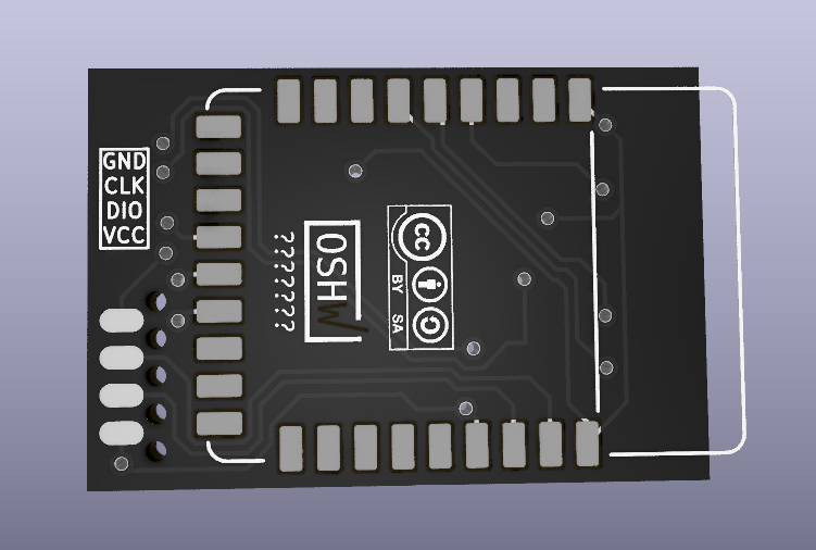
Well, the previous breakout finally ended up being an actual prototype design for thumbmouse. I realized that adding a BLE Module already completed the design. This way I can even have a prototype to play with instead of just the breakout. Behold the result:
On the back, a Seeed BLE Micro Module (NRF51822) would be mounted. The connector on the edge is the SOICbite which allows for SWD connection (and UART) without a connector. The power pads on the front are to supply power via a coin-cell battery (max voltage 3.6v). There's no 3.3v regulator on board to supply from battery directly (or external regulator).
I hope I didn't make any stupid mistake as I designed the board for this module while I never even actually played with any nordic chip.
I've been working on BicycleCompanion lately, and I'm close to ordering components to build a first prototype. With any luck, I will have something done for the HackadayPrize. I decided to order the basic parts to make a BlackBerry 9900 Trackpad module as well, now that I finally found a (supposedly) suitable connector. I'm thinking about a breakout that can be placed in the middle of a protoboard, but using castellated pads which would allow for soldering on top of pcb directly. What do you think?
PS: any help via KoFi is highly appreciated, it really helps me buy components and order PCBs for these projects. It goes without saying that I intend to publish the designs as open-source.
While I have a protoype working, as I mentioned previously, I have an issue of not having an appropriate connector for the two sensor modules I have. I actually found ONE manufacturer (I-Pex) that provides one that could work for one of the two models. I contacted them and requested a sample, however while they were nice it was basically "we cannot pay for shipping this product if you are not developing something commercially and have your own company". So, at the moment, I guess I will not get a connector.
The remaining option is to design a footprint for the sensor which has little holes in the pads. In theory I could add solder to the PCB and FPC and then melt them together this way, but it is a bit tricky and I'm not sure it will work.
I have written the schematic for the circuit though: I found appropriate PSU ICs for the 1.8v and 2.85v supplies and also included the MOSFETs for logic-level conversion. I have not yet designed the PCB as I'm not currently motivated to continue this in this way. In any case, I will most likely finish the PCB design in the future, when I make an order on digikey for some other parts and then I can order the required components for this board. Then, I will probably build a complete protoype, at least to finish this with something built. I will eventually decide if there's enough interest to work on this further or not.
In reality I lately became more motivated in picking up my BicycleCompanion project, for which I already have a working protoype. I want to do a second version with many new features and also with several improvements. Thus, I will direct my focus there at the moment.
In any case, let me know if you have any particular interest in this project or any questions or comments.
I have the trackpad working as a mouse! I will try to make a video of it, but it is difficult to show both the trackpad being used and the pointer moving on the screen. But, it indeed works. I'm amazed on how sensitive and precise it is. I'm actually able to move across the whole screen without much effort and at the same time, make small and precise movements. I'm not sure if Linux is adding some sort of acceleration to the pointer, but it works perfectly.
At the moment I'm polling the sensor via I2C since my interrupt line is not being converted to 3.3v (I'm reading the 1.8v line directly) and it does not work reliably as one would expect. Fixing this will eventually enable low-power reading of the sensor.
With this result I'm actually deciding on going ahead and design a PCB with everything needed for a wired version: USB connector, the two power supplies, logic-level converter and MCU (not sure if STM32F103, I might go with some STM32L MCU to eventually have a low-power design ready for a wireless version). I will also need some way of reading button presses. I will probably better to have capacitive touch buttons than mechanical ones, since I imagine it will be more comfortable. Also, I need to design this so that the device is not too big and I can design a part to be 3D printed to mount the whole thing on a finger.
Anyway, there's a slight issue with this: I need to find an appropriate connector for the sensor. I found some shady vendors on strange sites, selling blackberry parts. I would like to find something that I can buy from a reputable source such as digikey or similar ones. I don't really know if this kind of connector is supposed to be more or less standard or if it is custom-made for blackberry (seems unlikely). If you could help identifying I would be really thankful!!
Here's a picture of the BlackBerry 9800 sensor (the one I'm using) on the left, and a 9900 sensor on the right. It would be cool to find both, but I need at least for the 9800 one:
And here's a picture with a caliper included, for scale (each tick is a milimiter). So it is about 5mm from extreme contact to the other (and there are 13 contacts). So I figure the 9800 sensor has a ~0.4mm pitch connector:
Last few days I made some considerable advances so this will probably be a long post. TLDR: trackpad works!
Trackball
First thing I received was the blackberry trackball evaluation module. Since my expectation was that it would not be very accurate as a mouse replacement, I limited myself to simply analyze what was the actual resolution of the device. After connecting my cheap-o logical analyzer to the relevant outputs, I could see that there were around 9 pulses per one complete sweep of the finger on the ball (ie. the maximum that you could move the finger in one move). If you count edges, you then get about 18 counts. As expected this is a bit low. In fact, I tested only slightly moving the finger and indeed it required a bit of motion to get the first pulse.
In conclusion, this kind of interface is more to either replace a mouse scroll wheel or for other kind of projects altogether. For example, it could be used for navigating a GUI displayed on a small screen, avoiding the need for four buttons.
Trackpad
Now this is where it gets interesting. I was eager to try these modules and see what could I get from them. I bought four units: two BB9900 trackpads, and two BB9800. As mentioned in the previous log, these have 13-contact flexible PCB connectors. From my research, these present a I2C interface, instead of the SPI used in other models. Still, it was supposed to implement a similar register map than that of ADNS3060 optical mouse sensors. One extra difficulty in these models, though, is that it requires both a 2.85v supply for the sensor itself and 1.8v for the logic. This of course also means it requires a level-shifter to map 3.3v <-> 1.8v.
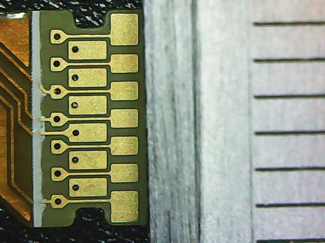
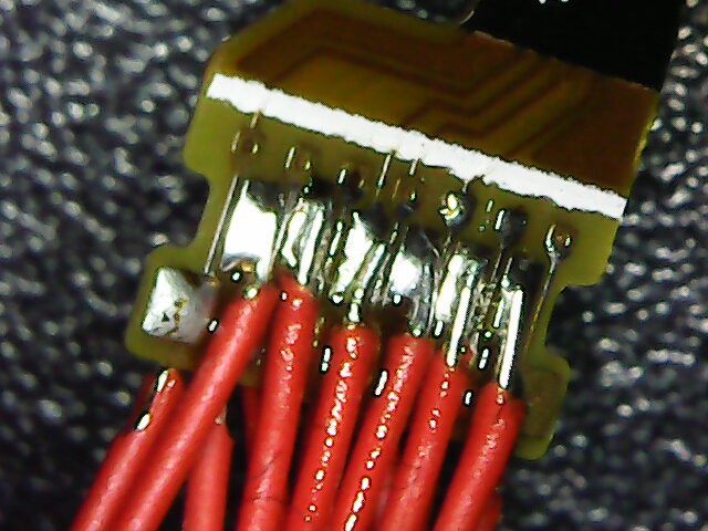
So, the first task was to solder some tiny wires to the connector and make a DIP-like module for it, so that I could place it on the breadboard. While I actually had a digital microscope on the way, I gave it a try in soldered the wires with the naked eye. I must say it ended up quite nice. Here's a picture with the microscope of the job done:
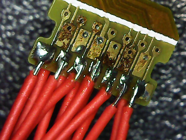
The brown part is some leftover flux. Or maybe it is a bit of burnt substrate, but it did not damage any of the fine traces. Also, I verified that there were no shorts. The module then looks something like this:
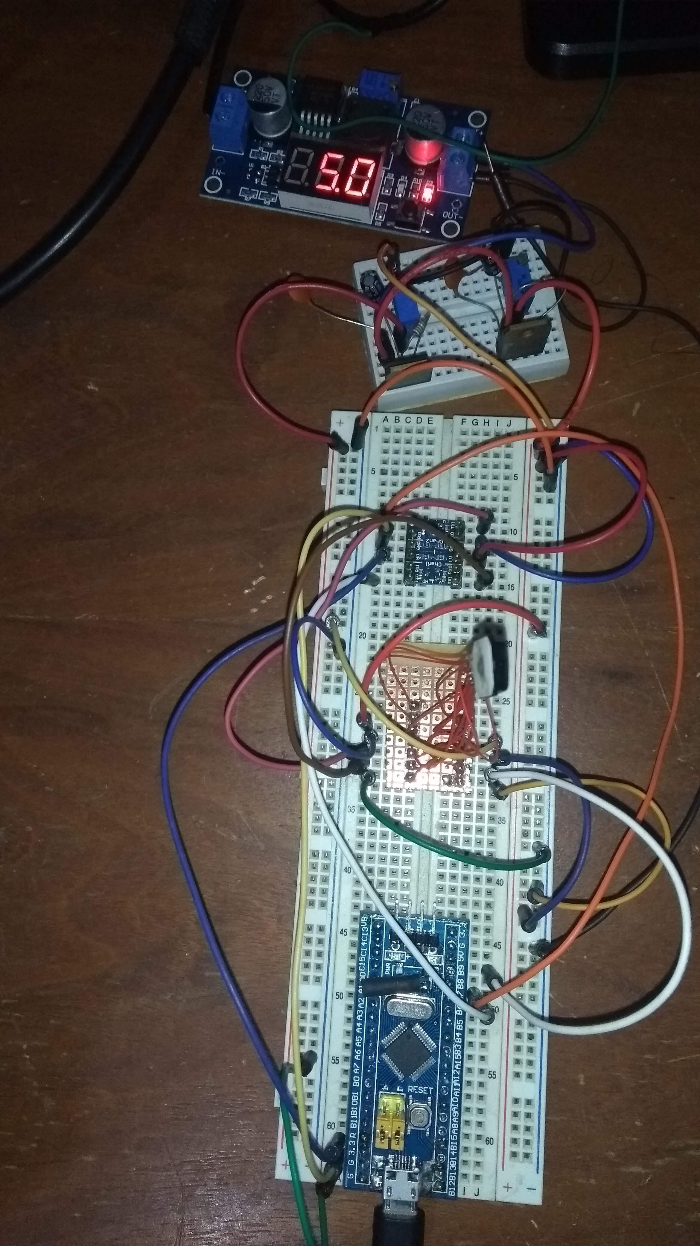
The second step was to build the pair of power-supplies. Using an switching adjustable power supply (my new low-cost bench PSU at the moment), I converted from a 12v wall adapter to regulated 5.0v. Then, I've built the 2.85v and 1.8v supplies using a pair of LM317's and a small breadboard. I then wired the supplies to the module and used the logic-level converter to map the SCL and SDA lines.
For testing I bought a BluePill board (STM32F103) but for some reason USB did not work (even after the R10 resistor fix). I then moved to an Arduino Pro Mini for initial testing. Later on, I re-used my old BluePill (which lacked the USB connecter) and transferred the malfunctioning board's connector towards the old board.
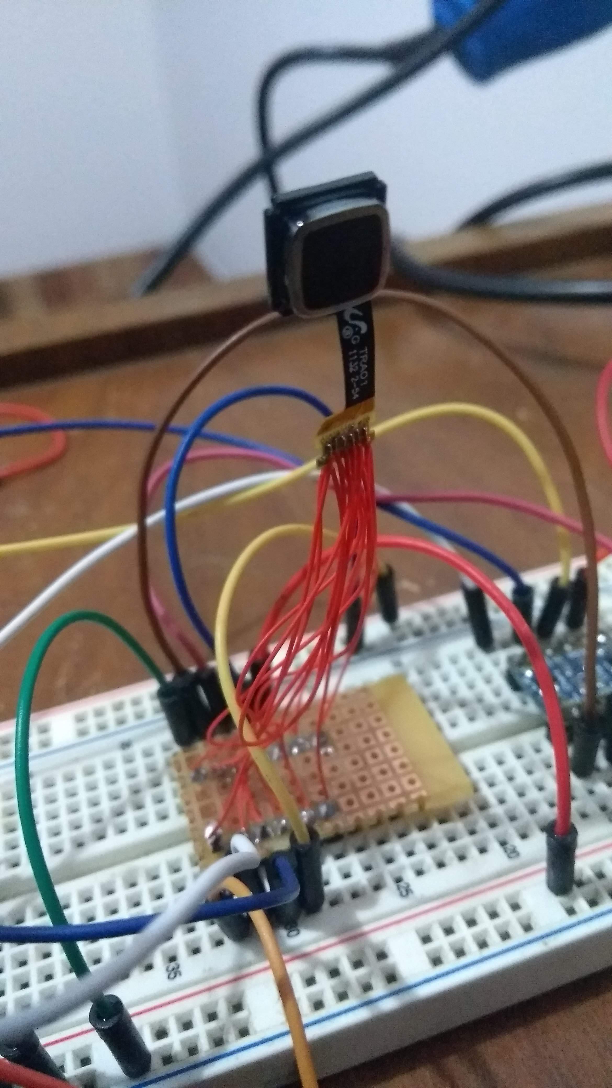
The complete test setup can be seen in the following photo:
Interfacing with the module
At first I encountered many problems which led me to think that it just was not possible to talk to the board. Maybe the pinout wasn't correct. Maybe this model was different. Anyways, after lots of trying I finally found that I had some wires setup wrong in the breadboard. But that was not all. While playing with the wires and running an I2C device scanner Arduino example, I suddenly got a response from a device with a 0x3B address. Then, after playing with the wires again I got a 0x33 address instead. At first I assumed it was noise in the line, but it was actually pretty consistent. Finally, I concluded that depending on the assigned SHUTDOWN pin value, and after resetting the module, it presented itself with either one of these addresses. I've tested for the expected motion registers and concluded that the one that worked was the 0x3B one, so I left the wires for that case.
Once I got that working it all went pretty well. From my tests, it seems that it mostly resembles an ADNS3050 actually, from the registers I got working. At the moment it appears that register 0x2 will have the 7th bit high whenever motion was detected. Thank, registers 0x3 and 0x4 can be read (separately! otherwise it does not work) to obtain a two's complement of X and Y deltas. Finally, the motion bit needs to be reset after reading these registers by writing 0 to 0x2. I also managed to set the device in 1000cpi resolution (instead of 500cpi) by changing a configuration register, which greatly improved response. I must say the device is really sensitive, and provides a nice range for fast movements. I think this is a very good mouse replacement.
Last thing I tried was to read the MOTION pin so that I did not have to poll the registers. This also worked perfectly, so everything I could need for now is there.
Next steps
I will now write a driver for the module for NuttX. I already have a driver for emulating a mouse (or any HID device) from NuttX. So by writing a simply app that reads the trackpad and writes to the emulated mouse I can have a working version. I will post again when that is done. After that, I'm thinking which direction to go. Option a) is to design a small PCB which would include the appropriate connector for the flex PCB (is that connector even standard? If you know how to track the part number, please let me know) and encloses the MCU and USB port. This would be a functional wired prototype. Another option is to continue prototyping in order to get to a wireless version (maybe Bluetooth or something NRF24L01 based). This also requires dealing with battery chargin circuit and a battery small enough to make the device small.
 Matias N.
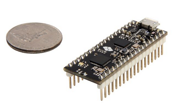
 The main changes are:
 So, I soldered the BLE module using the iron and I started getting bridges below which were really difficult to correct. Eventually I accepted that I had to use hot air to try to remove it. This took me long time since the module sucked a lot of heat. Eventually I managed to remove it but I ripped a pad of my PCB in the process. So, know I needed to populate the tiny PCB for the third time! Also, I didn't know if I cooked the module in the process or not.
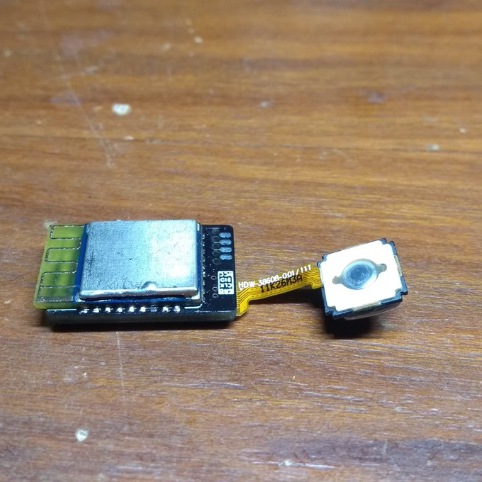
![[video-to-apng output image]](https://im.ezgif.com/tmp/ezgif-1-80c46ab5bd0c.png)
 While I was still waiting for the batch of passives I ordered, since I had some resistors and capacitors of acceptable values I decided to go ahead and solder this. I still don't have the BLE module (it is sleeping in some post office storage building for some days now), I figured it would be best to first try and test this via an external MCU, since I would not want to solder the BLE module to a useless board since it was a bit expensive.
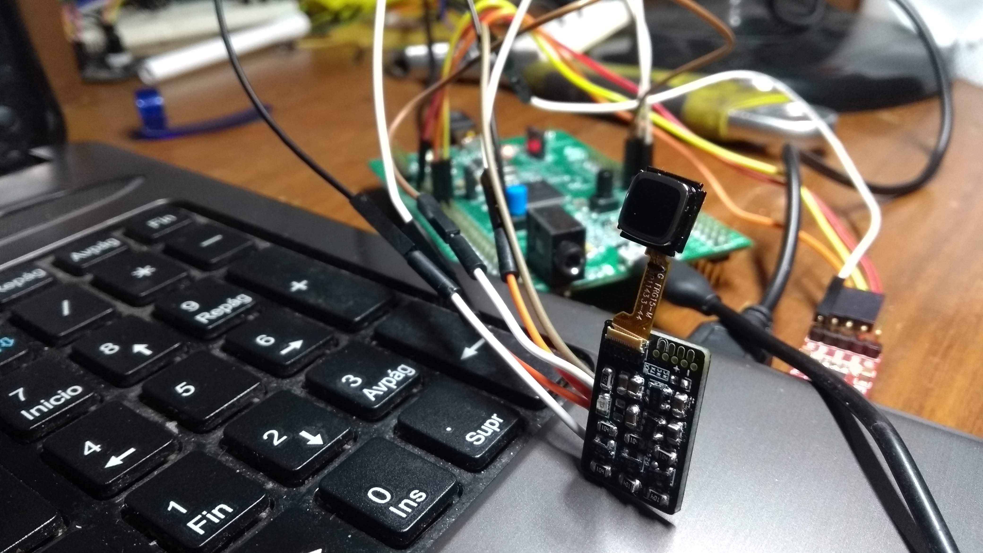
 PS: any help via KoFi is highly appreciated, it really helps me buy components and order PCBs for these projects. It goes without saying that I intend to publish the designs as open-source.
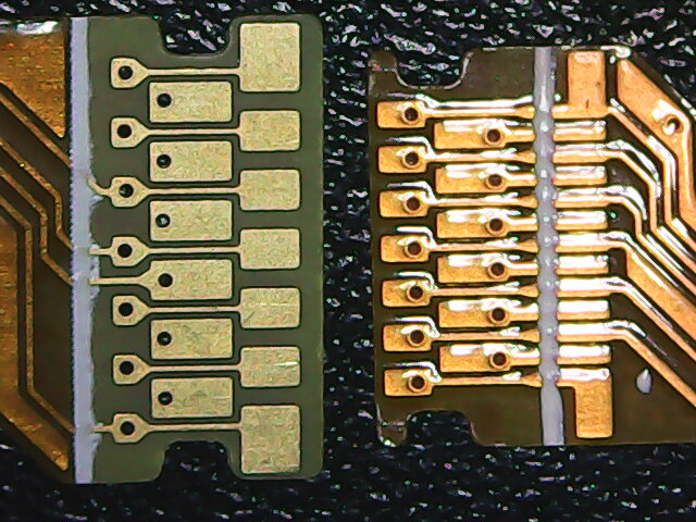 And here's a picture with a caliper included, for scale (each tick is a milimiter). So it is about 5mm from extreme contact to the other (and there are 13 contacts). So I figure the 9800 sensor has a ~0.4mm pitch connector: