-
1Get to know the components
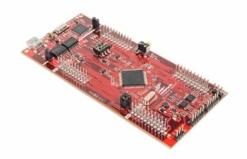
Microcontroller Texas Instruments F28069M C2000 launchpad
This microcontroller is embedded in a development board whose features makes it suitable for developing applications such as the Data Acquisition System and the ECU:
- USB debugging and programming interface
- CAN bus interface with integrated transceiver
- 14 ADC pins (Analog to Digital Converters)
- 34 GPIO pins (General Purpose Input/Output)
- 2 serial protocol (SCI) communication channels
- 2 I2C protocol communication channels
- Programming with the free software Code Composer Studio
It manages the external sensors, the GPS, the storage of the data inside the USB, the communication with the ECU and the communication with the dashboard’s screen.
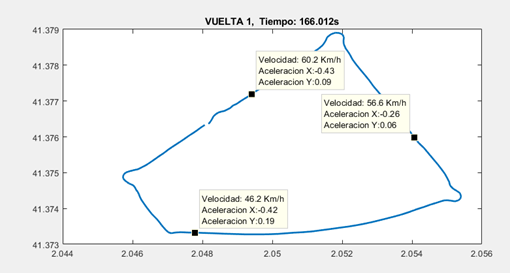
PC with Matlab software
Matlab software is used to process and analyze the data stored in the USB. The position and trajectory of the bike can be visualized together with the value of the sensors, simultaneously, as can be seen on the picture.
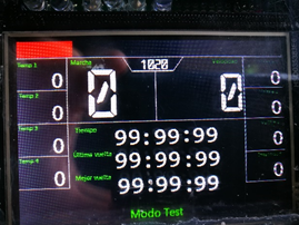
Nextion Enhanced 5.0’’ screen
It’s used to show the most relevant information to the pilot, as well as the status of the bike’s systems. It receives the data from the F28069M C2000 microcontroller via serial communication.
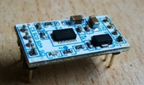
GPS GY-GPS6MV2
The GPS gets the instant position of the bike, so that its trajectory can be afterwards plotted in Matlab software along with the values of the other sensors. It sends the GPS data to the F28069M C2000 microcontroller via serial communication.
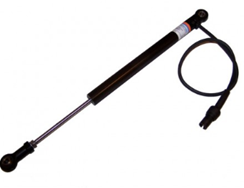
AIM suspension Sensor
Installed on the front and rear suspension, the suspension displacement of the bike can be measured.
Accelerometer VMA204
It is used to measure the acceleration and forces the bike withstands in the axes x, y, and z. It sends the acceleration data to the F28069M C2000 microcontroller via I2C bus communication.
Keypad
The keypad is used to select the driving mode (ECO, Sport), configure the pilot’s screen and control the data acquisition times.
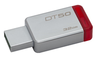
USB
It stores the data from the sensors, the GPS and the ECU.
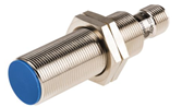
Inductive sensor IME18-08BPSZC0S
It is used to count the pulses of a magnetic part of the wheel. The higher the speed, the more turns will the wheels do and the more pulses will the inductive sensor count. That’s how the measurement of the speed works.
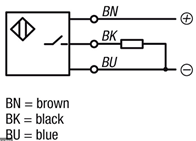
The connection diagram is the following:
Temperature Sensor pt100
The pt100 sensors are an specific type of temperature detectors. It varies its resistance depending on the temperature. The most important feature is that its composed of platinum and have an electrical resistance of 100 Ohm at 0ºC.
Voltage regulators
The system needs 4 different voltage regulators in order to obtain the voltage levels needed for the microcontroller and the sensors:
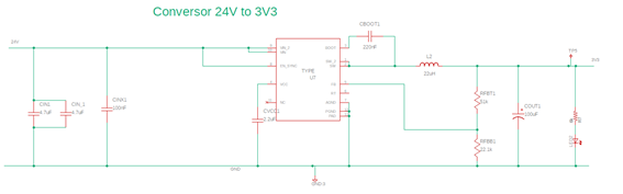
LMR23615DRRR
It is able to convert from a wide voltage range supply to a fixed output voltage. For this application, we need it to supply 3.3 V to the Texas Instruments F28069M C2000 microcontroller.
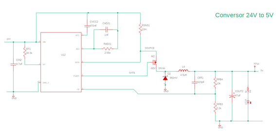
LM25085AMY/NOPB
It is able to convert from a wide voltage range supply to a fixed output voltage. For this application, we need it to supply 5 V to the Texas Instruments F28069M C2000 microcontroller.
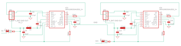
MAX16903SAUE50
It is able to convert from a wide voltage range supply to a fixed output voltage. For this application, we need 2 of them:
One to supply 5 V to the external sensors that require such voltage.
The other one to supply 3.3 V to the external sensors that require such voltage.
FDD5614P mosfet
A mosfet is a semiconductor device similar to a transistor used to commute signals.
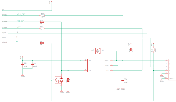
TPS2051BDBVR Power switch
This component is used to prevent short circuits. When the output load exceeds the current-limit threshold or a short is present, the device limits the output current to a safe level by switching into a constant-current mode. If the overload does not stop, it cuts off the supply voltage.
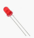
LEDs
LEDs are used to visualize whether the system has power or not. They also keep the current flowing in only one direction, preventing the wrong polarization of the circuit.
Diodes
They work as a LED but without the light; they keep the current flowing in only one direction, preventing the wrong polarization of the circuit.
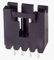
Connectors, pin headers and adaptors
The PDB board requires a certain amount of connectors, pin headers and adaptors of different characteristics in order to work and integrate with the different peripheral devices:
5-103639-3
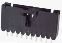
5-103669-9
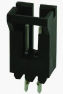
5-103669-1
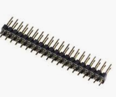
Pin Headers
The size of the pin header can vary easily by dividing the pin header into separate parts.
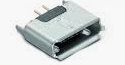
MicroUSB_AB
Allows the mechanic adaptation of the board to the USB device.
Resistors, capacitors, inductors
The basics for any electronic circuit
-
2Make the schematich design of the board
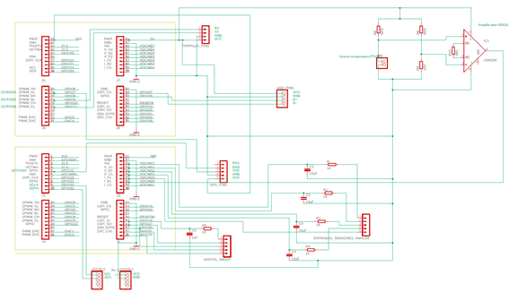
The circuit schematic and components’ connection are showed in the images below:
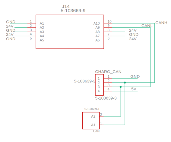
External connectors for power supply and CAN communication
Microcontroller Texas Instruments F28069M C2000 launchpad
Featuring:
- Sensor’s connection, via pin headers of different sizes for analog and digital inputs
- Signal conditioning for the sensors:
- Low pass filters for preventing electromagnetic interference to disturb the signals. The cut off frequency is 15Hz.
- Wheatstone bridge and an instrumental amplifier for the pt100 temperature sensor to work correctly
- Communication pins for external devices:
- SCI for the screen and the GPS
- I2C for the accelerometer
Power supply to the microcontroller
Via Voltage regulators, which convert 24V (low voltage coming from the battery) to 3.3V (LMR23615DRRR) and 5V (LM25085AMY/NOPB):
USB connection
Power supply to the sensors and external devices
Via Voltage regulators (MAX16903SAUE50), which convert 24V (low voltage coming from the battery) to 3.3V and 5V. The system is redundant and can also provide power to the microcontroller in case its voltage regulator fails:
-
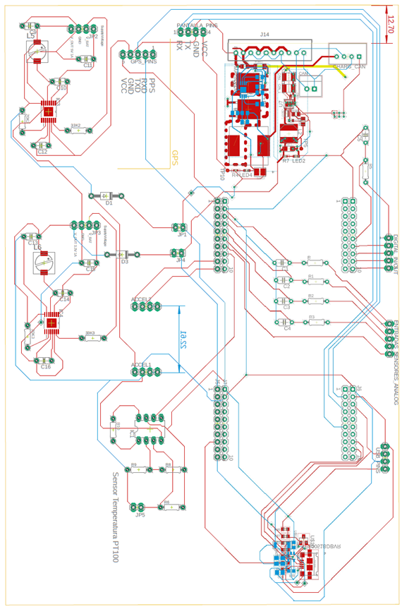
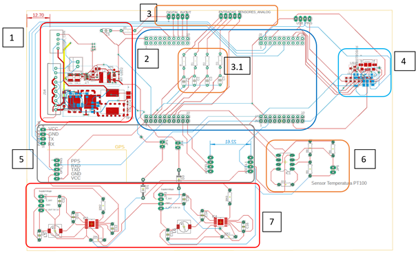
3Design the PCB Board Layout
1) Power supply for the microcontroller
2) Microcontroller Texas Instruments F28069M C2000 launchpad
3) Digital and analog inputs and signal filtering (3.1)
4) USB connection
5) External devices pin headers
6) pt100 temperature sensor signal conditioning
7) Power supply for the sensors and external devices
-
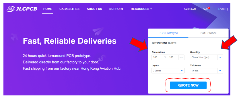
4Order PCB board
With the design completed, it’s time to order the PCB in the web JLCPCB.com. The process is simple, as you just have to go to JLCPCB.com , add the dimensions and layers of your PCB board and click the QUOTE NOW button:
JLCPCB are also sponsor of this project. JLCPCB (ShenzhenJLC Electronics Co., Ltd.), is the largest PCB prototype enterprise in China and a high-tech manufacturer specializing in quick PCB prototype and small-batch PCB production. You can order a minimum of 5 PCBs for just $2.
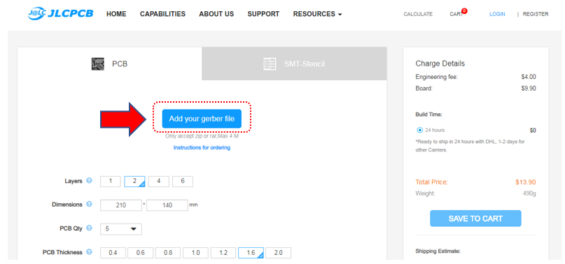
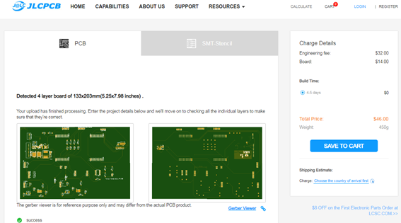
You need to generate the gerber files of your project and put them in a ZIP file. By clicking to the “add your gerber file” button, the design is uploaded to the web. The dimensions and other features can still be changed on this section.
When uploaded, JLCPCB will check everything is correct and show a previous visualization of both sides of the board:
After making sure the PCB looks good, we can now place the order at a reasonable price by clicking on the “Save to cart” button.
Data Acquisition System for MotoStudent electric
Data Acquisition and Data Visualization System for a MotoStudent electric racing bike
Discussions
Become a Hackaday.io Member
Create an account to leave a comment. Already have an account? Log In.