Maakbaas
-
Redesign and PCB
08/16/2020 at 14:44 • 0 commentsThe linear clock has been on my desk since it has been finished. However, there were a few issues with the design that I wanted to address. First of all, the build quality could have been better, and the build process was quite involved. But more importantly, the display was not very readable in some conditions. In this update I will address these issues and present the second version of the linear clock design.
-
Display modes
01/19/2020 at 12:17 • 0 commentsFor the final log on the clock I will go into more detail on the software side. First I will briefly discuss the software architecture. Then I will explain the different display modes I developed so far. All code can be found on the GitHub repository for this clock.
---------- more ----------
Since the name of this project is the 'linear calendar clock', the calendar mode was the priority to implement 🙂. After some struggling I managed to implement the Google API as you can see in the animation below. I decided to split up the software in a part that is running on the ESP8266 itself, and another part that is running on a server to pre-process the data.![]()
The Google calendar link in action
The software running on the ESP8266 is based on a template I developed for previous projects. Basically what the template implements is a Wifi connection and a web server. If the ESP8266 is not able to connect to a WiFi network, it will start a hotspot. If you connect to this hotspot from an external device you can set the WiFi details in a web page, which will then be stored into EEPROM and used during the next boot.
On top of this the ESP8266 implements the https request functionality to request from the internet what data to display. The Adafruit neopixel library is used to drive the LEDs. The data to be displayed is coming from endpoints that I wrote in Node.js to run as a Netlify function, since this can be used for free and I used Netlify already to host my website as well. You can see an example of how the code would work below.
var moment = require('moment');

var offset = 0;

exports.handler = async (event, context) => {
    const resp = moment.utc()
                       .add(1,'hour')
                       .format('HHmm');
    return {
            statusCode: 200,
            body: resp
    };
};
The Node.js endpoint serving the time in the correct timezone to the ESP8266
The time will be output as a 4 number string containing the hours and the minutes. So far I did not yet implement a clock functionality in the ESP8266, which would of course be perfectly possible. I could also have used a RTC as a back-up, but instead I opted to keep the setup as simple as possible and just request the new time periodically. That would look something like this:
http.begin(client_ssl, request_url);

String payload;
if (http.GET() == HTTP_CODE_OK)
{
    payload = http.getString();
    int hours = payload.substring(0, 2).toInt();
    int minutes = payload.substring(2, 4).toInt();

    float floatHours = (hours + (float)minutes / 60) * 2;

    for (int i = 0; i < NUMBLOCKS; i++)    {
        if (i + 1 <= floatHours)
            blocks.setPixelColor(i, blocks.Color(30, 30, 0));
        else if (i + 1 == ceil(floatHours) && minutes % 30 >= 15)
            blocks.setPixelColor(i, blocks.Color(60, 30, 0));
        else
            blocks.setPixelColor(i, blocks.Color(0, 0, 0));
    }

    blocks.show();
}
The ESP8266 code to read the time from the endpoint and display it on the clock
This code reads in the string from the endpoint and transforms it into a number to know which bars should be lighted, and which shouldn't for the normal clock mode.
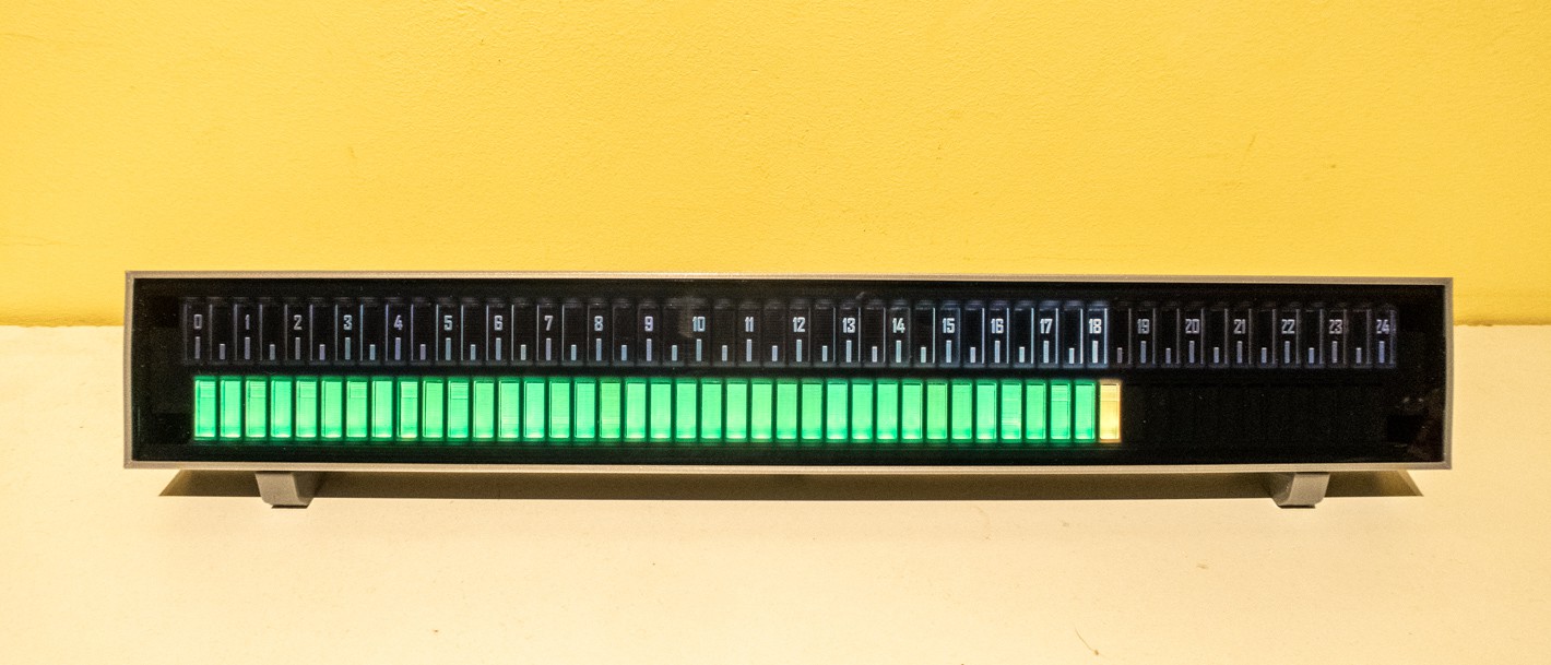
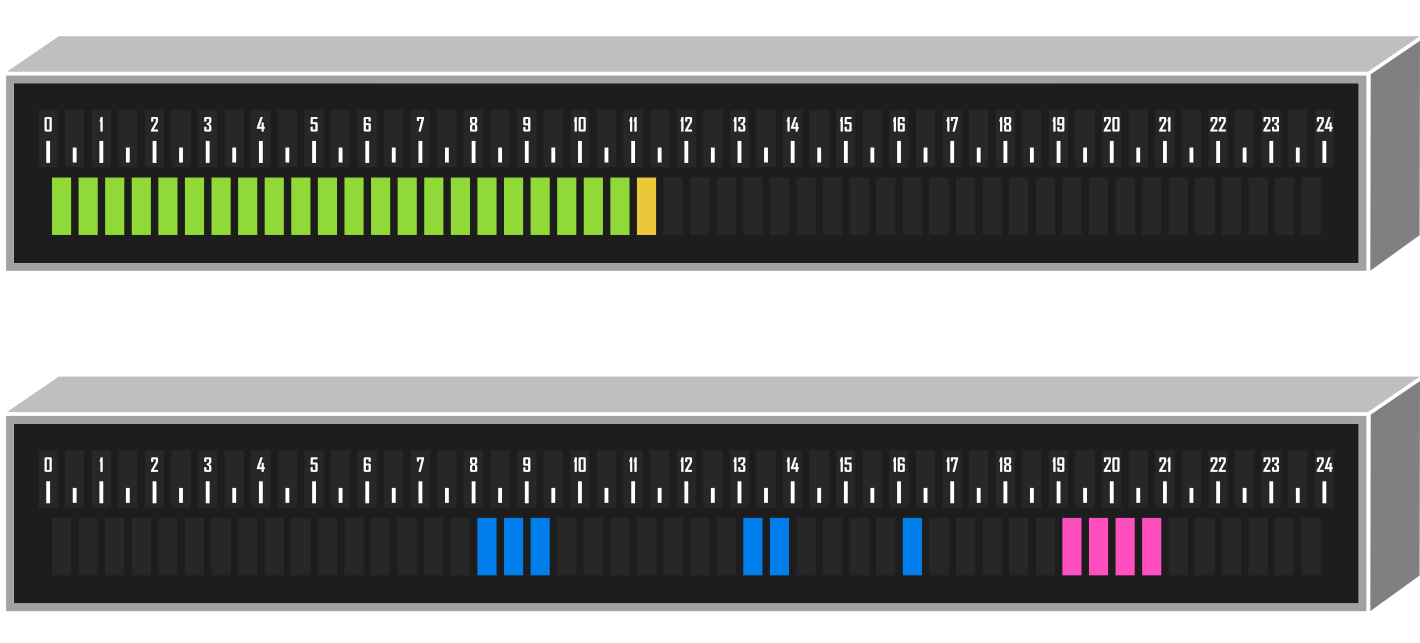
Normal clock mode
In the normal clock mode, the bars are lighted green to show the current time in half hours. In addition, if a quarter has passed, the last LED will show in yellow. This can also be seen in the code example above. I could probably have implemented more colors, or rules to be able to read the time even more granular, but that would be beside the point for this clock, and make reading the time less intuitive.
![]()
It's a quarter past six
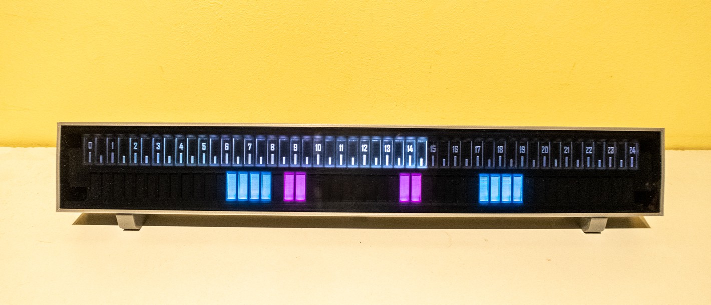
Calendar mode
The highlight for me is the calendar display, which is in part what triggered me to design a linear clock like this. This Stackoverflow answer was a big help for me to implement the Google API in my endpoint. This was an area where I did not have any experience before. I also implemented support for multiple calendars to be able to show them in different colors. Baiscally the endpoint returns a 48 number string, with a 0 for no appointments, and a number corresponding to the different calendars for busy time slots. As with everything the final code can be found in my GitHub repo.
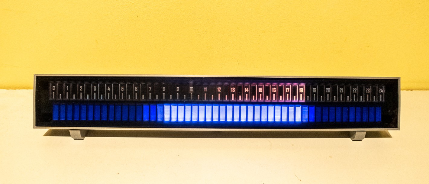
In calendar mode the actual time is shown in the top half of the clock. The tick marks have increasing brightness up to the current time. After that they are shown a bit darker again. Until now this is the best balance between aesthetics and functionality I found.
![]()
It is half past two and my next appointment is still more than two hours away
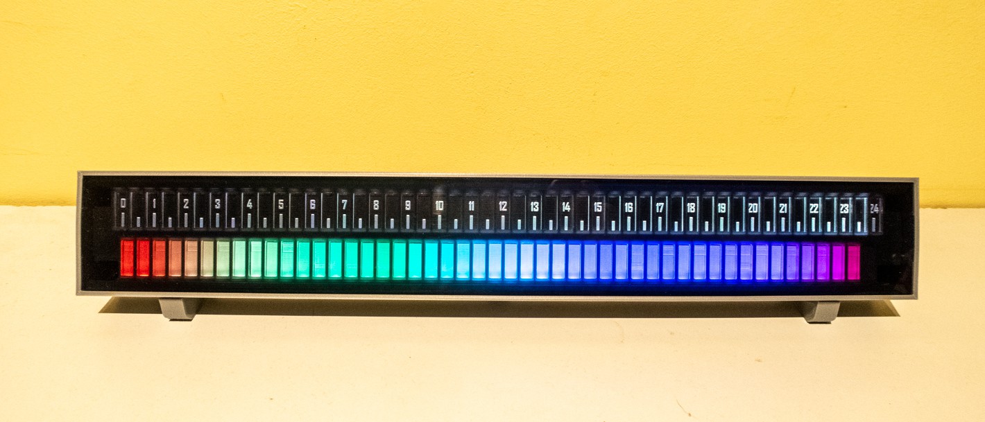
Rainbow clock mode
In this mode the time is also deducted from the number of lighted blocks, but what better way to show off RGB LEDs than to display a rainbow 🌈? To do this the ColorHSV function is used. With this it is quite easy to make a color gradient. Behind the scenes the Neopixel library will convert this back to RGB values. The same time endpoint is used, only the processing in the ESP8266 is different.
![]()
It is 23:30, the most beautiful time of the day
Daylight display mode
In this mode the clock bars show astrological, nautical and civil twilight to tell you exactly the day and nighttime for the current day. In addition the time ticks will light up in different colors to show the actual time. If the actual time is at night the ticks will be shown in white, if the actual time is during the day the ticks will have the color of the sun, becoming more orange and pink when the time is during sunrise and sunset. The endpoint for this display is implemented using the API from sunrise-sunset.org
![]()
It is six o'clock, if you can't look outside, enjoy the little sunset on the clock
Goal tracking mode
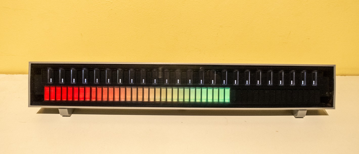
Finally, the clock can also be used as a goal tracking display. I did not implement an endpoint for this yet since it will depend completely on which goal you want to track. Think of something like a saving goal from your budgetting app or the target number of steps from your fitness tracker. In this mode the display can not be used as a clock, and the numbers 1-24 will be hidden by disabling their LEDs. Also the display can be set up with different red, orange and green zones, depending on your targets.
![]()
You're well on your way to meet your goal!
Wrap-up
Even though I could implement a number of other modes and enpoints, I consider the project finished for now ✅. Other ideas could be to show hourly stock gains and losses, or expected temperature or precipation. This would simply be a matter of writing a new endpoint and implementing the color strategy in the ESP8266. If you have any other ideas to improve the design, or if you have started to build your own, I'd be happy to learn about it!
-
Housing and Assembly
01/12/2020 at 18:50 • 2 commentsNow that all the physical components are available it is time to finish the housing and assemble the full clock. First I will talk about the housing design, and the process of getting it printed. After that I will show the final product when it is all put together.
---------- more ----------
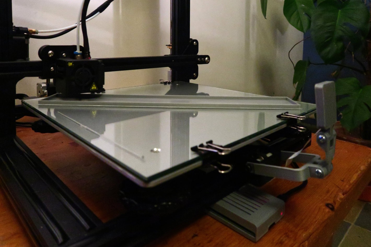
As you could see from the concept drawing in my introduction I wanted to go for a simple and square design of the clock and the housing. Even though I used the most dense LED strip with 144 LEDs per meter, the clock was still going to be over 35cm in length. The good news is that my 3D printer is a Creality CR-10S, which has a bed size of 300x300mm. You might think: hey, but that is not enough... But by printing it diagonally on the bed it just fits!![]()
Printing the housing on my Creality CR-10S
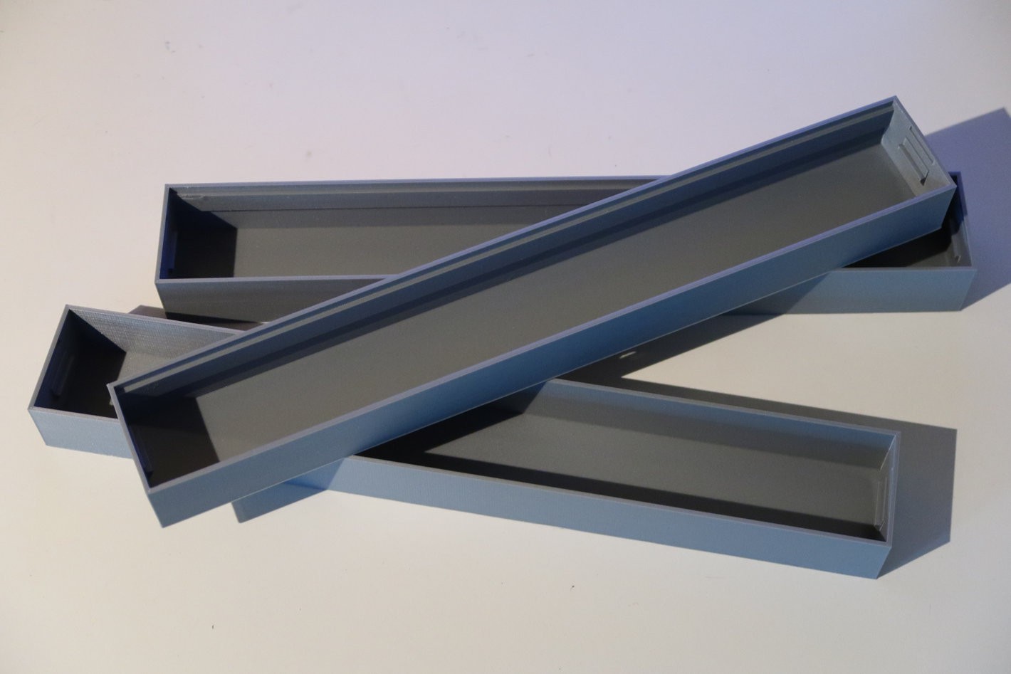
This is the first project where I have used my own printer. It turns out that the main benefit of 3D printing at home is not necessarily rapid prototyping, but rather rapid iteration. I designed everything to be press and snap fit into the housing, such that I could always disassemble the clock in the future. However, to make all the fits right I had to go through three iterations. If I would have had to order these three iterations from a service like Shapeways, I would have lost weeks of time, and almost the total price that I paid for my printer.
![]()
After more than 30 hours of total print time: third time's a charm!
Final Assembly
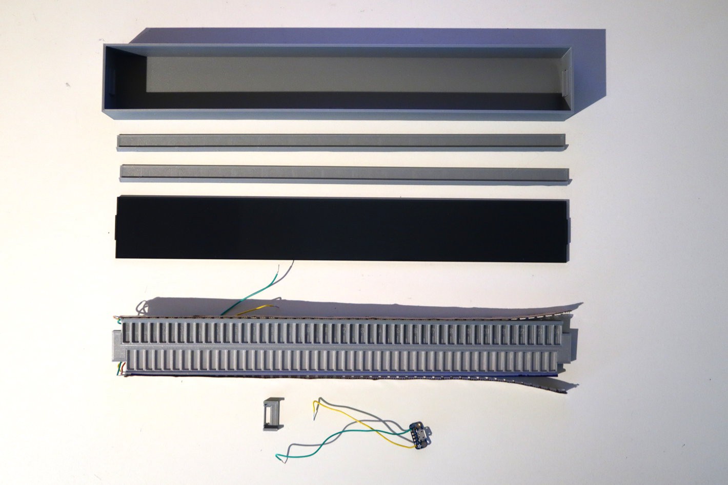
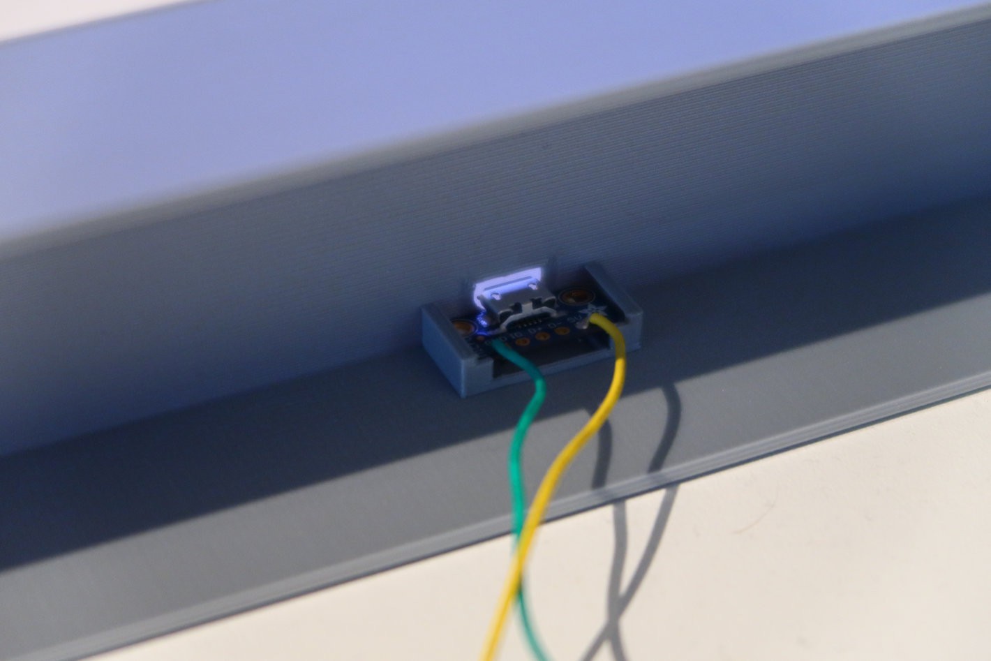
With the housing finished, it was time to put everything together. I put the ESP8266 at the back side of the frame, to have the core of the clock with the frame, LED strips and electronics into one unit. Next to that I printed two guides to fit the core frame into the housing, as well as a small part to fit the USB port to the back of the housing.
![]()
All components ready for assembly
![]()
Fitting the USB port into the back of the housing
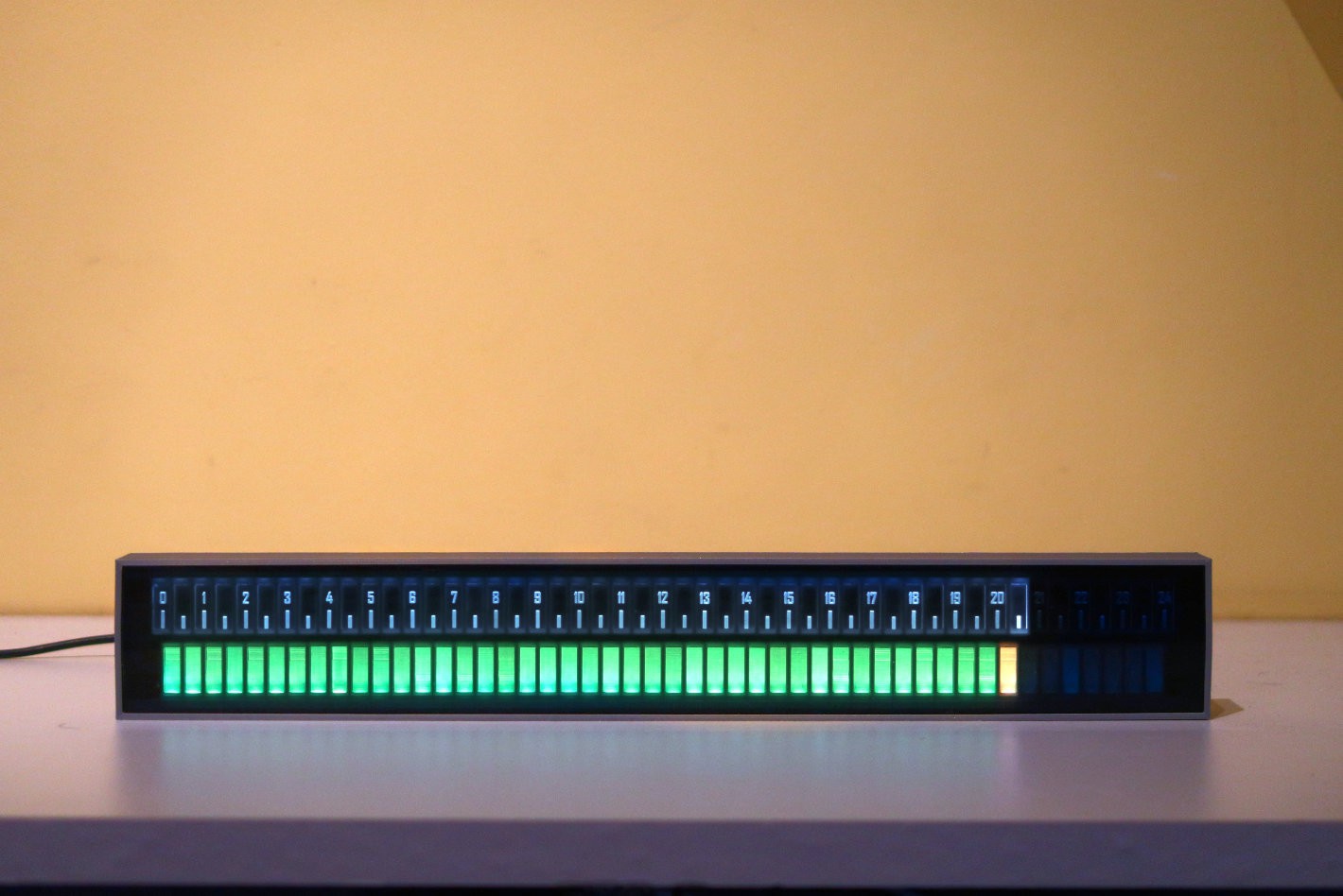
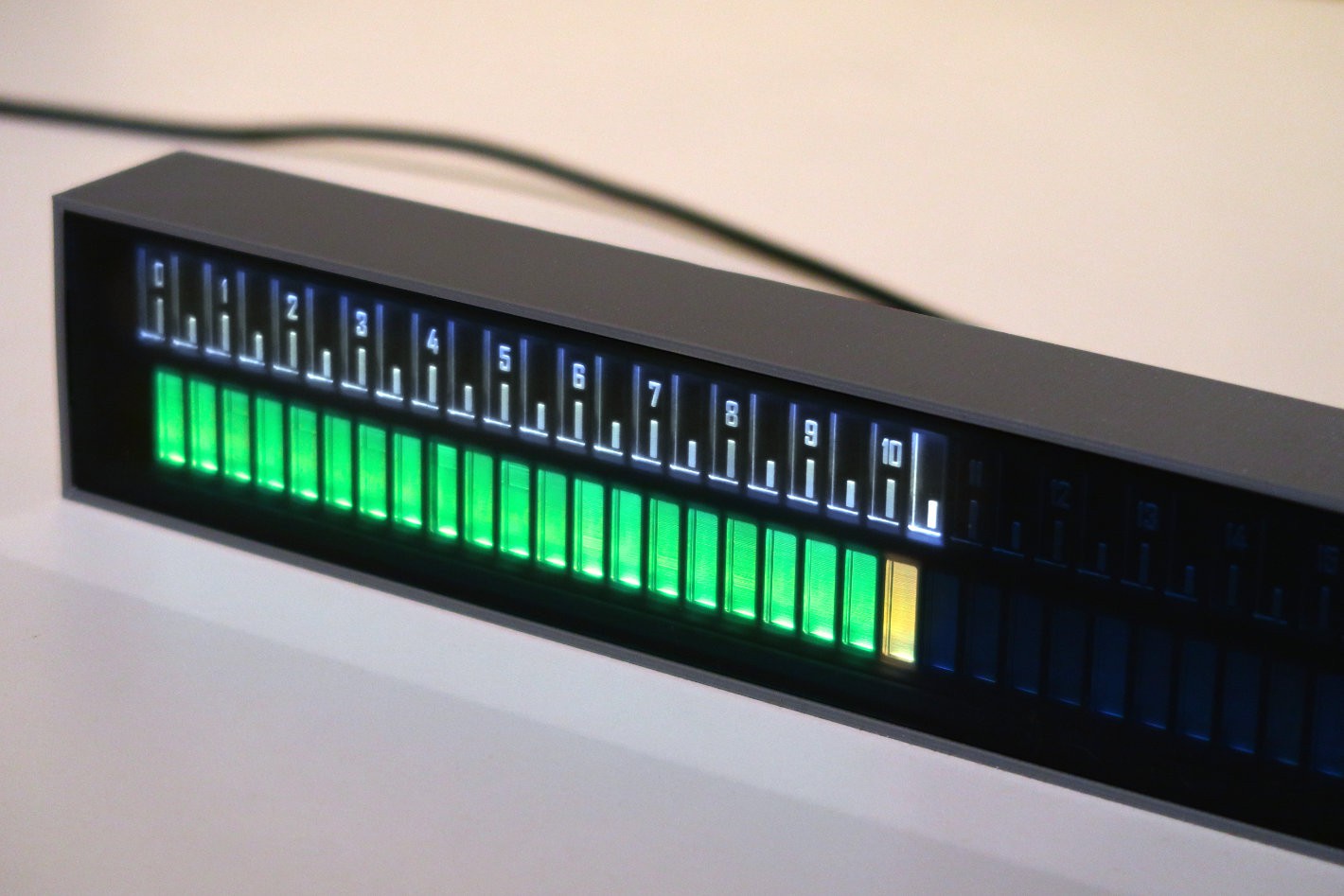
After putting everything together I am quite happy with the result. You can see the final product in the pictures below. In the next update I will go into more detail into the software and discuss which data I want to show on it, and how to display it. So far I mainly focussed on the hardware and did not really work on the software yet.
![]()
![]()
The finished clock after assembly
-
Let there be light
01/04/2020 at 21:18 • 0 commentsIn this second log I will introduce the electronics used in this project and design the frame to hold the light guides that I designed in the previous log. At the end of this article you will see a first teaser of the fully functional light system for the clock. Let's dive into it!
---------- more ----------
First of all, let's start with the electronics used for this project, which will be really simple since there are only two main components:ESP8266:
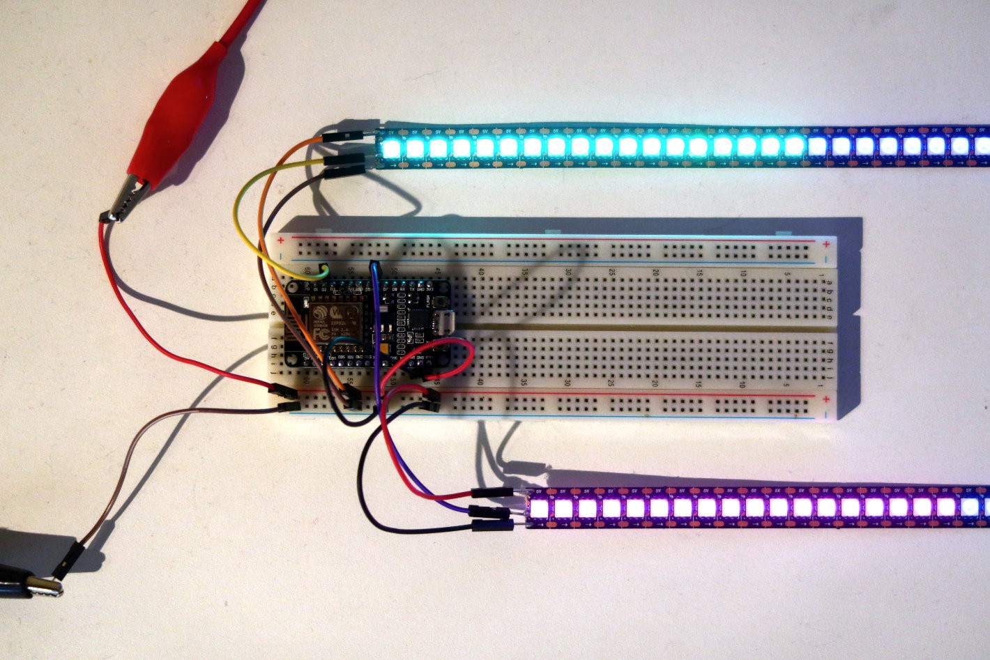
I will use a development board with an ESP8266 to handle the WiFi connection to pull data from the internet. The ESP8266 will also directly drive the LED strip.WS2813:
I have no particular reason to have chosen the WS2813 over some other LED strips such as the WS2812 or the APA102. My main requirement was to have a LED strip with 144 LEDs/m to ensure the clock will not become too large.![]()
Lighting some LEDs was a piece of cake with the Adafruit Neopixel library.
A note about level shifting: strictly speaking I would need to transform the 3.3V signal from the ESP8266 to a 5V signal for the LED strip. However, because of the fast timing not every level shifter works. The ones I had lying around did in fact nothing at all to the voltage when I measured it. The internet recommends for instance a 74HCT245 level shifter, but I did not have this one available. Based on some encouraging comments on this Hackaday post I decided to skip the level shifter altogether, and that seems to be working fine so far 👍.
Designing the Frame
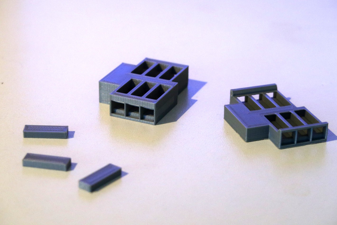
You can read here about the light guides I designed for this clock. I wanted to design a frame to hold all these little pieces in place directly behind the front panel. But as it turned out there was an issue with that. The LEDs on the strip are 5x5mm, but the strip itself is actually 12mm wide. Because of that there is roughly 2.5mm of strip that extends beyond the front. To not complicate the housing too much I decided to put the light guides further back in the housing and came up with the following prototype parts:
![]()
First prototype on the left, improved version on the right. The small pieces are surrogate light guides while waiting for my laser cut parts.
In the first design I simply made the housing thicker before the slot for the light guides. I did not think of it at first, but the main problem with this approach is the viewing angle. When you would look at the clock from the side with this design, you would look at the walls of the frame, and not see the numbers themselves. Because of this I made a second revision where I made the frame in front of the light guides as thin as possible.
![]()
The first large part I printed on my 3D printer with a length of 35cm. I needed the entire bed length of the bed. Diagonally.
Assembly
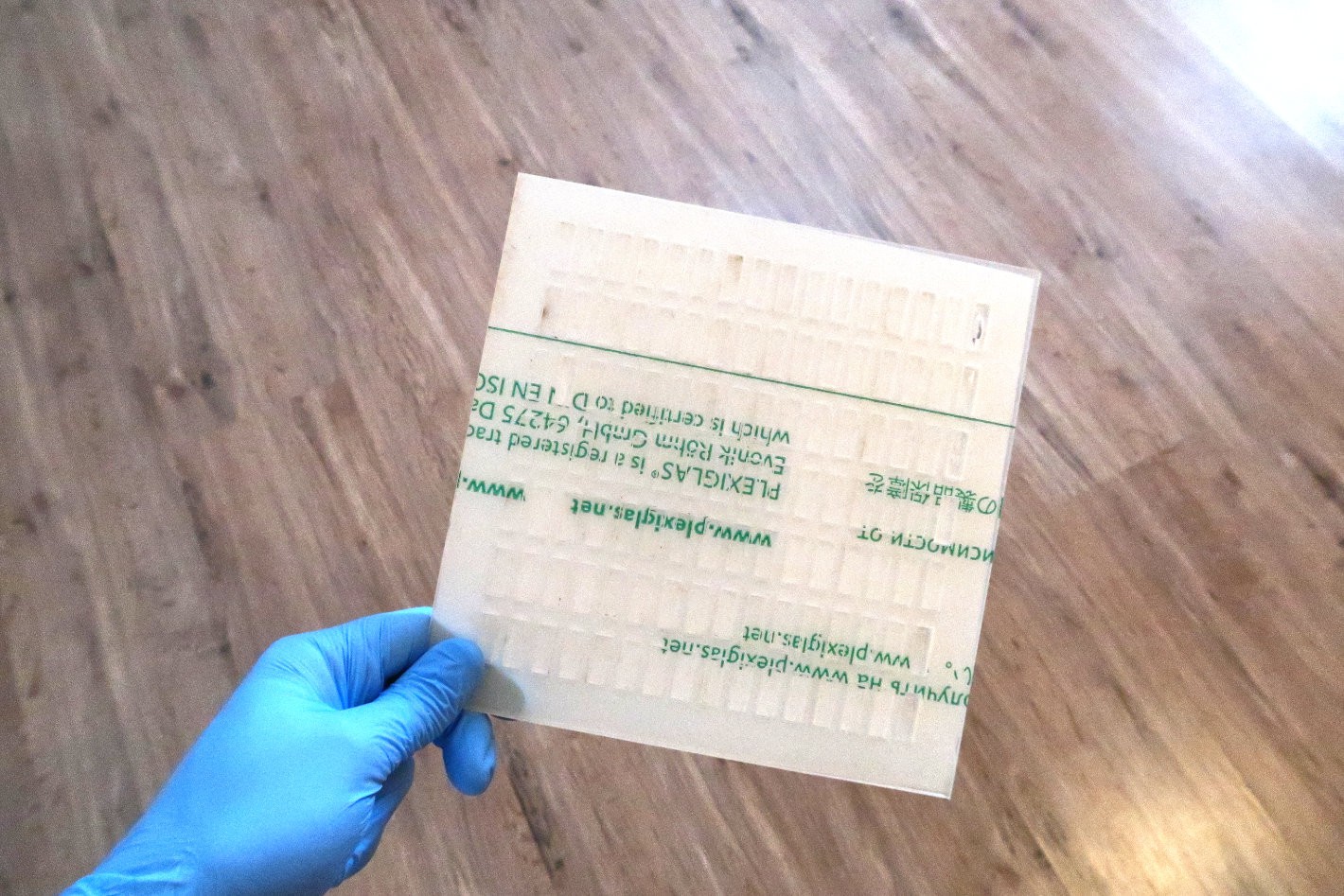
The good news is that in the mean time I received my laser cut parts, so I could immediately start the assembly by inserting the 97 small light guides into the frame. The fit was perfect, if anyting some of the slots were a little bit too snug 😇, but I managed to get them all in place.
![]()
![]()
The gloves are there to prevent fingerprints which might impact the quality of the lighting.
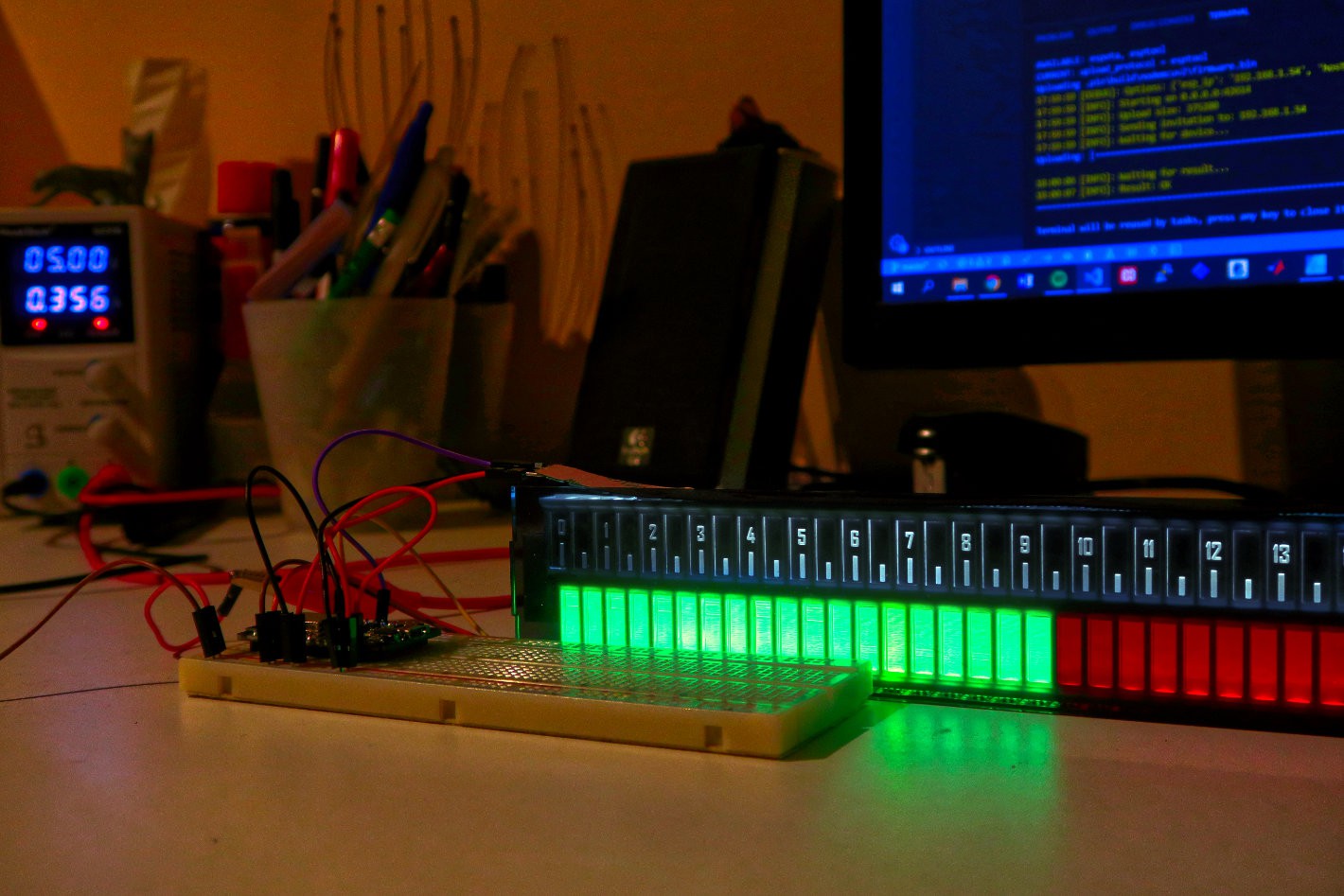
In the end the frame worked out great. Below you can see the frame in action for the first time with the LED strip just laying on top. In the next posts I will finish the assembly with the full housing, and start working on the software. I alread have quite some ideas of displaying different kinds of data with this display:
- The time
- Calendar or schedule
- Weather information
- Night, daylight sunrise and sunset
- Hourly stock gains and losses
- If you have any other cool ideas don't hesitate to tell me!
![]()
It's already starting to look awesome.
-
Clock Design
12/25/2019 at 15:17 • 0 commentsIn this first project log I will discuss the design for my clock. The idea for this clock is not to accurately track time to the second, but rather to show the progression of time throughout the day. Furthermore, the clock should be able to display additional information, such as your schedule for the day.
---------- more ----------
Before the start of the project I made two design decisions. First, the clock should be a linear clock. This design is not very common for a clock, but especially for the idea that I have in mind, makes a lot of sense. Computers introduced the progress bar to us, so by now reading one should be very intuitive. The second design choice is to use addressable RGB leds. This is something new for me, and using them will open up many new project possibilities.![]()
First design mock-up. The top view shows the clock and the bottom view is an example for how a calendar could be displayed.
In the picture above a sketch of the design is shown. In this post I will focus on the design itself. There are three parts to the design: the housing/frame, front panel, and light guides. The housing will be 3D printed whereas the other parts will be laser cut. Since I have a (new 😎) 3D printer at home I designed the laser cut parts first, because they have the longest lead time. The 3D printed housing as well as the electronics will be discussed in a later post.
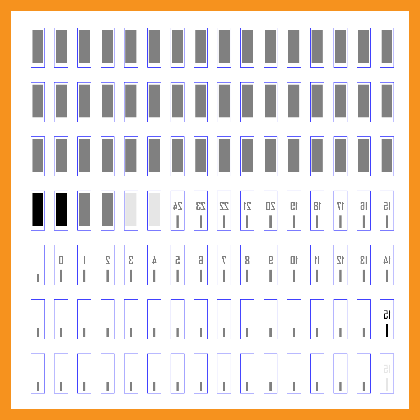
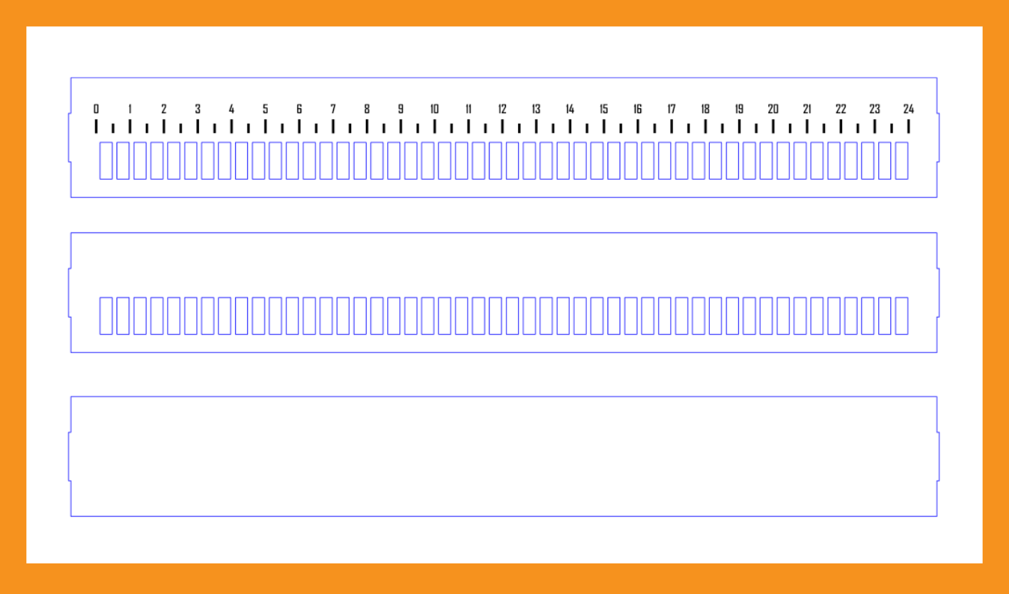
Light guides
I want the final product to look as close as possible to the mock-up shown above. The squares of light should have sharp edges and be nicely diffused. Furthermore, I also want the numbers and tick marks to have back-lighting. For this I chose to experiment with laser engraved acrylic, such as used in the Lixie display and various other edge lit signs .
![]()
My laser cutting order for the light guides. Each block and each tick marker is a separate piece which will later be held together in a frame.
The working principle behind this is quite nice. To put it simply: light that has entered inside the acrylic will reflect internally and stay trapped inside of the light guide, unless the angle between the light beam and the surface becomes too large. Then, when you engrave something on the surface, the surface becomes rough so that the light hitting the surface there will scatter in all directions. This will make the engraved shape light up.
In this case I will have a LED strip at the top and bottom of these pieces so that the light will be reflected to show the squares and tick marks on their face. The engraving will be placed on the back side (hence the mirror view of the numbers) so that the front face will look more clean when not lighted. I opted for medium density engraving since that looked the best in the examples, but also included a few pieces at different levels so that I know for the future how they compare.
Front Panel
As I mentioned before the housing will be 3D printed, but this is not the case for the front panel. I am not yet sure what the best look will be, therefore I have ordered three different versions. From top to bottom:
- The first design is done for a two color material. The front panel will be black with cutouts for the led blocks, but not for the numbers. these will be engraved in the front plate resulting in white markings. Of course this means that the numbers and ticks can not be lighted, but I wanted to see this in person to judge the look.
- The second design is ordered in a transparent dark grey acrylic. This will hopefully give a somewhat darker front while still transmitting all the light coming from the leds behind. To give the front some more relief, I have still cutout the led bars.
- The final design is from the same material, but now without any cutouts. This will be the most clean look. I am curious how they will compare in practice.
![]()
My laser cutting order for three different variants of the front panel.
As you can see, each panel also has subtle extensions on the left and right side. I hope to use those to click the front panel into the housing. I have used a similar method in the past successfully. This prevents the need for glue so that I can always disassemble the panel later.
Linear Calendar Clock
In this project I use adressable RGB leds to make a linear clock. The clock will be connected to Google Calendar to show my appointments.