-
Assembly and calibration
05/18/2020 at 16:13 • 0 commentsI decided to put all electronics (incl. photoresistor and Arduino) on a circuit board. This can be attached to one side of the water tank, while the laser LED will be on the other side - maybe together with a battery pack. Some cables will have to run around the backside of the water tank.
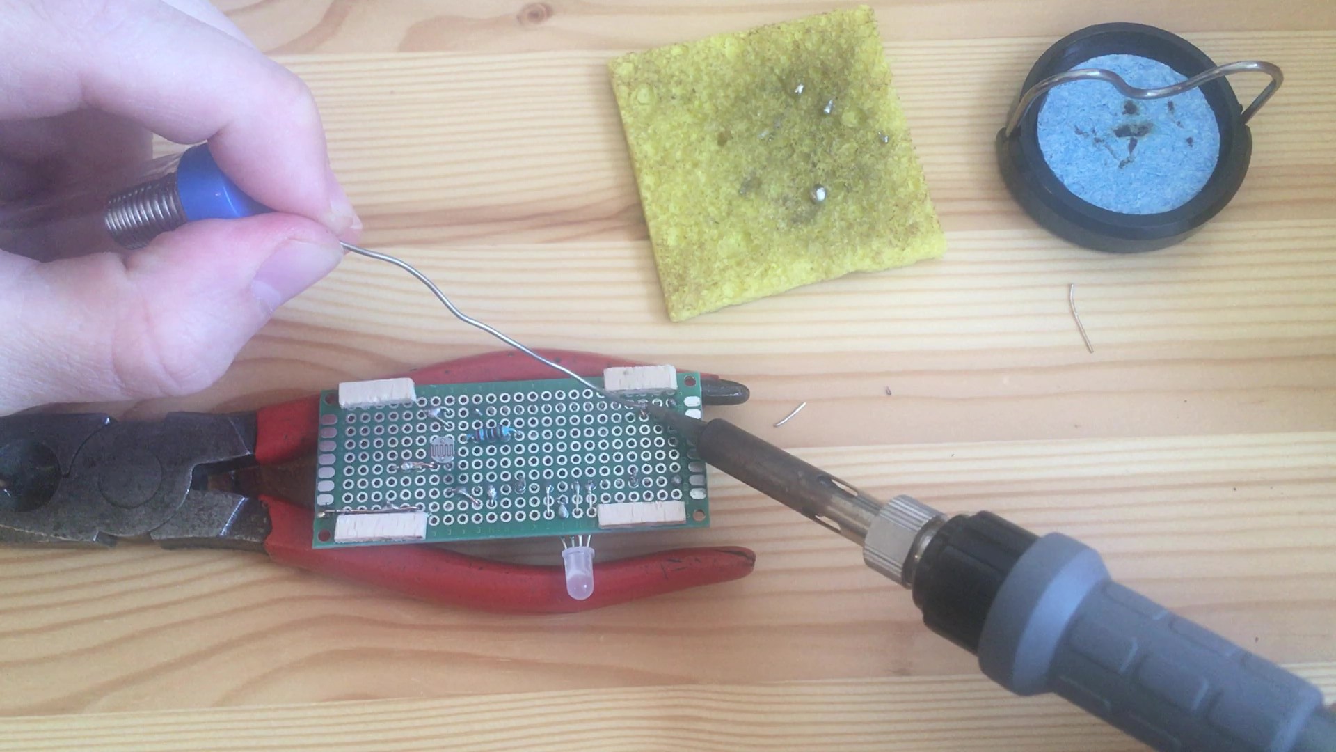
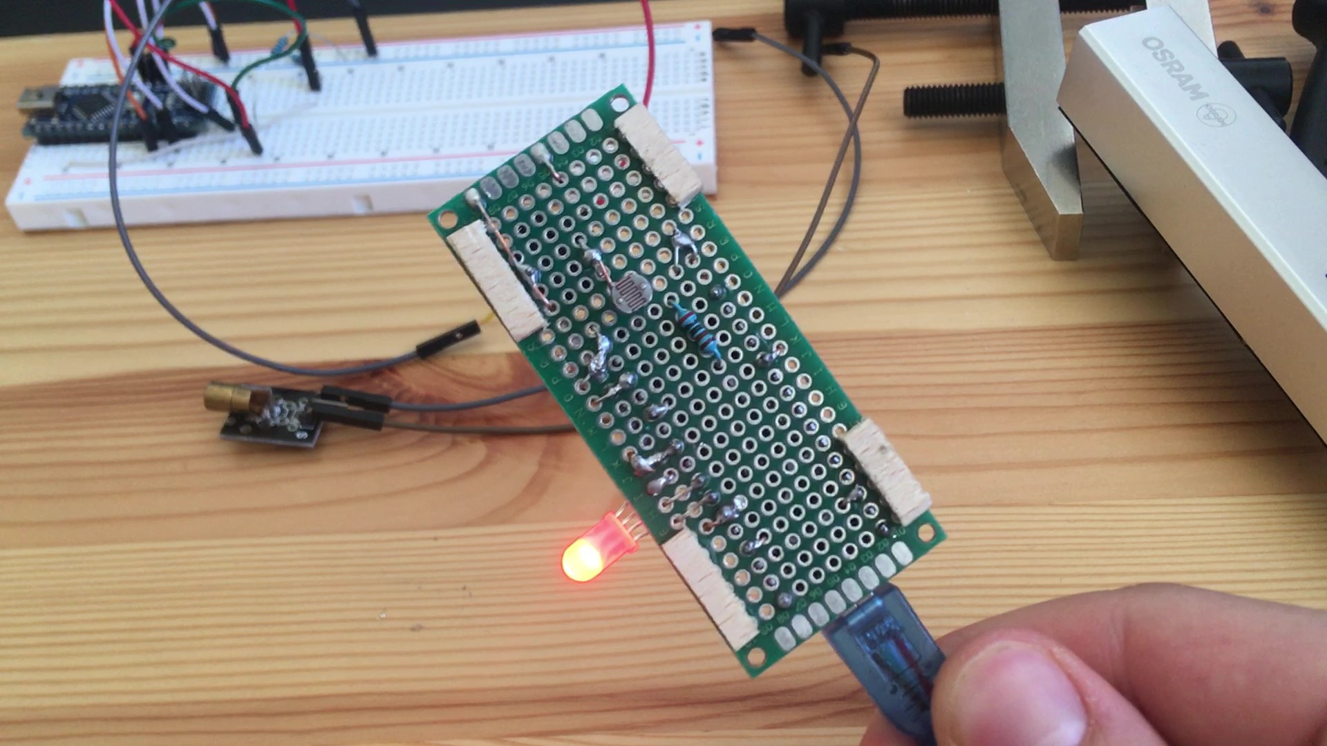
Circuit Board
I chose a 30x70 mm² perfboard because I wanted the flat plane I had to attach to the curved tank as small as possible. The photoresistor had to face towards the water tank while the Arduino and most components should face outside, so the board could be brought as close as possible to the tank. This is why I used both sides of the perfboard for components and wiring. I uploaded the diagram to the project.
![]()
![]()
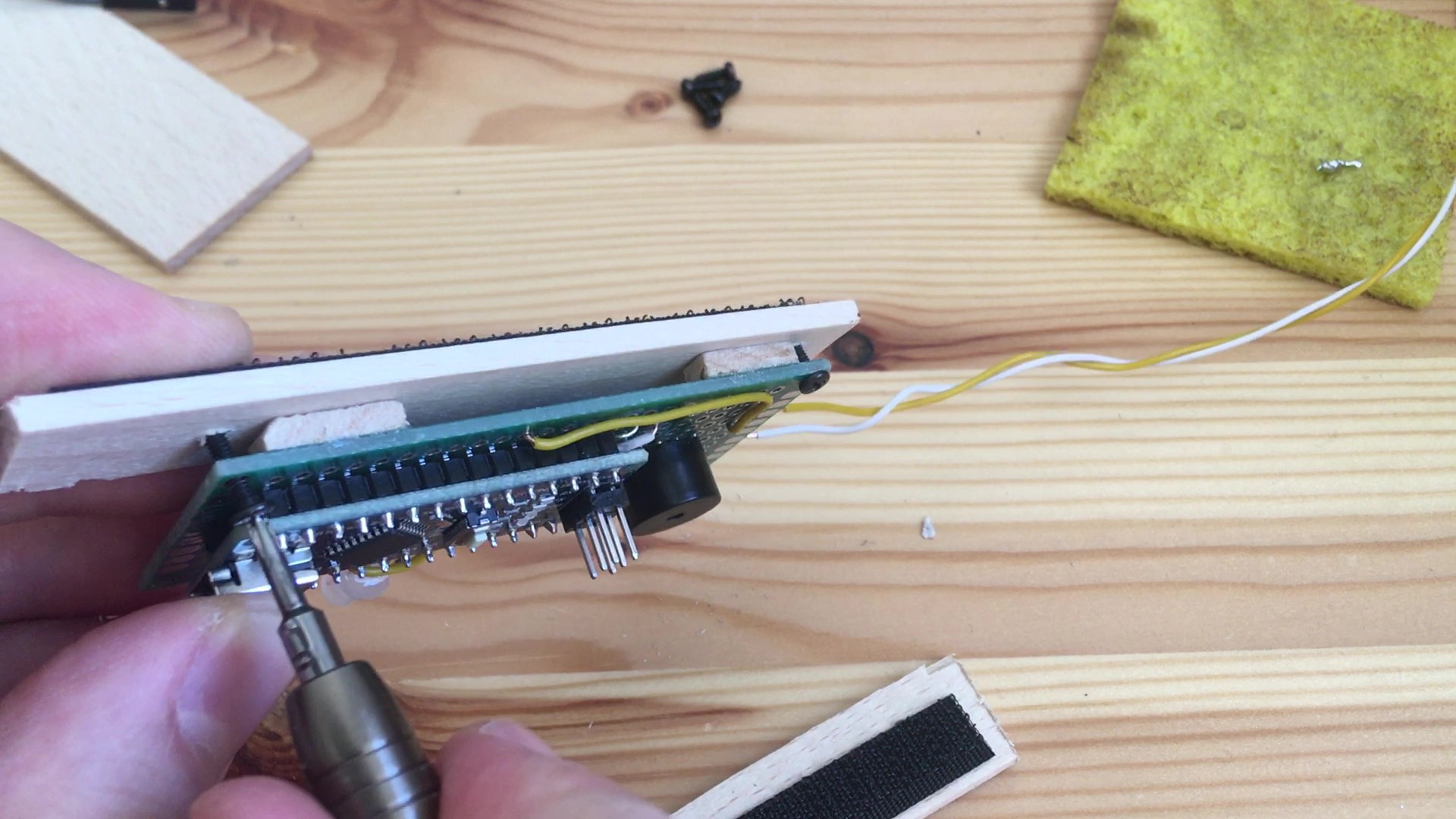
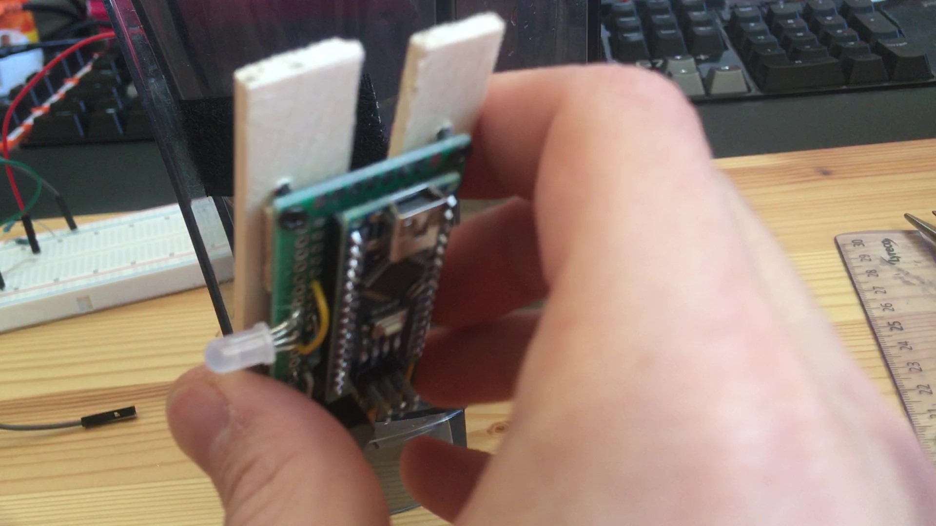
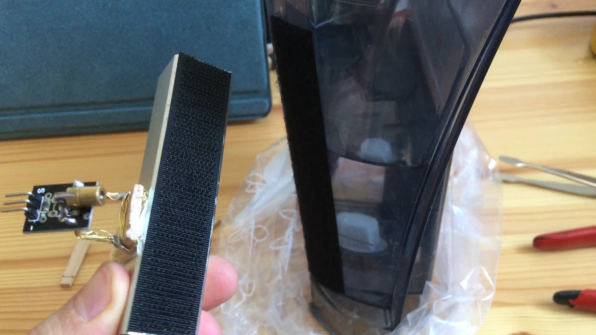
Basis and mounting
I decided to mount the circuit board onto a piece of plywood which I could attach to the water tank. I wanted everything to be removable and adjustable (in order to be able to choose different water levels as thresholds and line up sensor with laser), so I used velcro tape. I put the "hard" side on the circuit board and the "soft" side on the water tank.
![]()
![]()
![]()
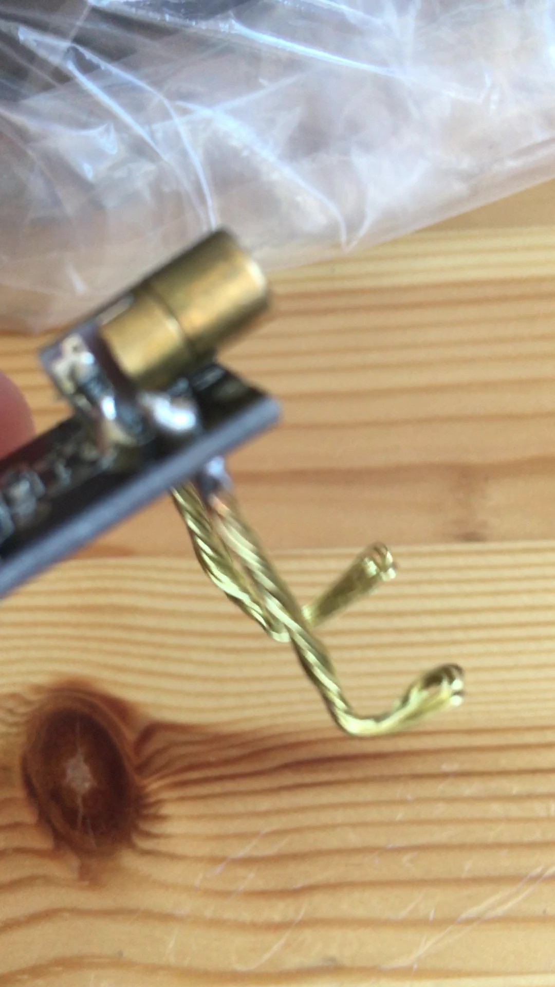
Laser and battery pack
The laser LED is also driven by the Arduino, so I ran two wires on the other side of the water tank. I wanted to have extra flexibility with laser adjustment so I mounted it with some thick wire on another piece of plywood. At first I thought about attaching this directly to the water tank but since I decided to use a battery pack instead of power line, I glued it to the battery. I attached the battery with the laser on the water tank with velcro tape.
![]()
![]()
Calibration
Two different types of calibration were necessary. After attaching both sides to the water tank, I turned the Arduino on and adjusted the angle of the laser so it would hit the photoresistor through the water. Then, I monitored the resistance values via serial port and changed the thresholds to reflect real-world conditions. I uploaded the code to my Github repository which I link to in this project.
-
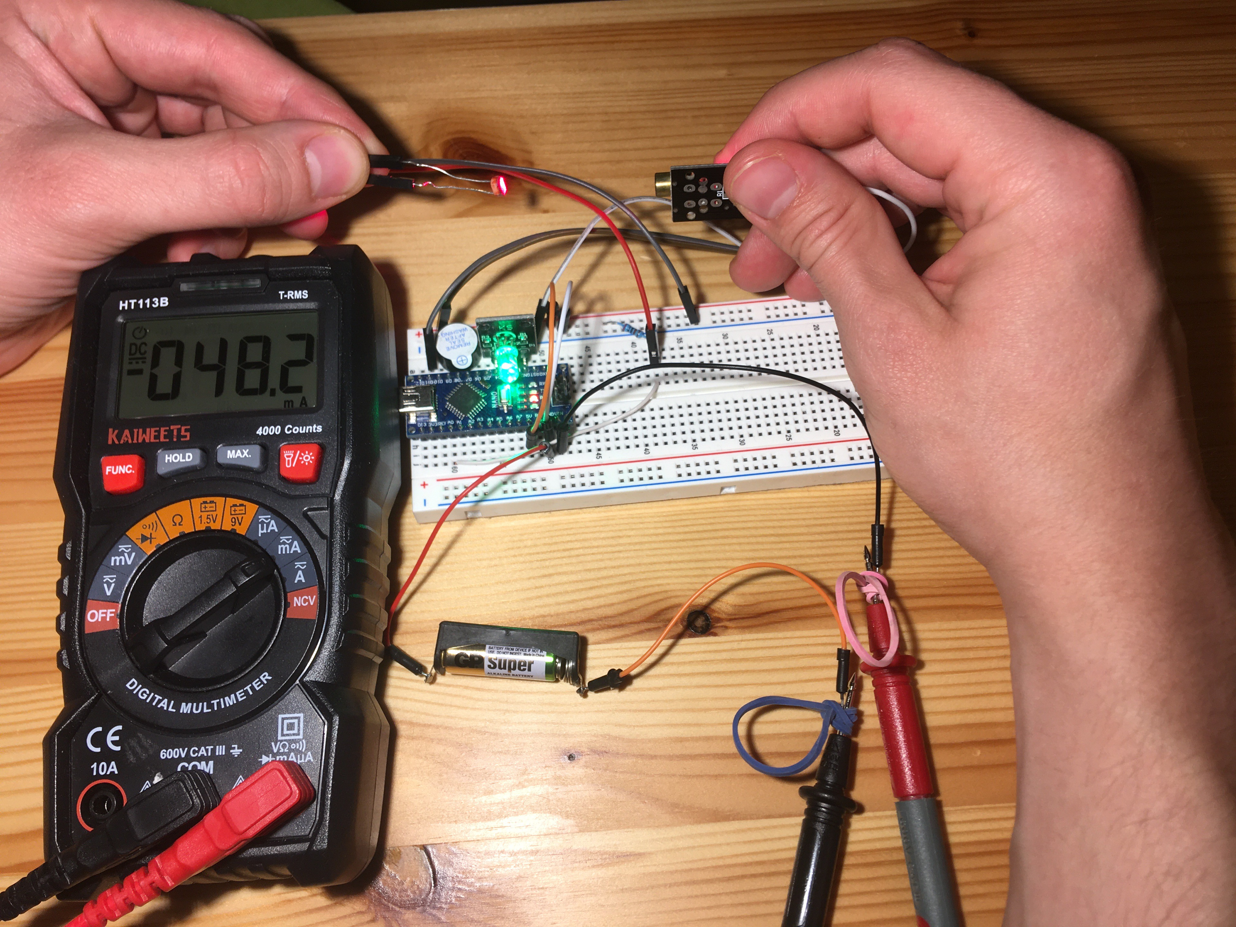
Component tests and calculations
05/15/2020 at 06:38 • 0 commentsNext up, I tested all the components under different circumstances to find out 1) under which conditions to operate and 2) if I could possibly replace them.
Photoresistor
I replaced the photoresistor devboard with a standalone photoresistor integrated into a voltage divider circuit. When the photoresistor is "on", its resistance gets very small and most of the voltage drops over the other resistor. If the photoresistor is "off", its resistance gets very large and most of the voltage drops over it. To find out ideal nominal resistor and "on"/"off" thresholds, I tested the resistance under different conditions.Condition Laser 100% intensity Laser 20% intensity completely dark 300,000 300,000 fully lighted 20-50 120-150 through water tank - below water level 5,000-10,000 5,000-10,000 through water tank - at water level (refraction) 100-130 350-370 through water tank - above water level (air) 300-500 600-800 Laser will be operated at 50% intensity at first, but this can be further calibrated. I want to set thresholds for detecting enough water ("on") below 350 Ohms and not enough water ("off") above 1k Ohms. For this, I want to use a nominal resistor of 1k. This way, the voltage thresholds are far enough apart (1.3V and 2.5V respectively) and the resistance is always large enough so only a small current flows (max. 4.5 mA).
Nominal resistor in Ohms 330 1,000 2,000 5,000 "on" voltage (% of 5V) 51% 26% 15% 7% "off" voltage (% of 5V) 27% 50% 33% 17% difference (% of 5V) 24% 24% 18% 10% max. I in mA 12.5 4.5 2.4 1.0 Laser LED
When Laser Board is "full on" (5V to GND), 29 mA are measured. This means, the nominal resistor on the board is ~120 Ohms.
With this information, I could rebuild the Laser Board with a standalone Laser LED. I don't have one though and the solder joints on my prebuild board seem sketchy, so I don't want to remove it from there.
In an attempt to reduce energy consumption, I also tried to replace the laser with a normal yellow LED. This light is not focused enough though and the photoresistor won't detect it through the water tank.RGB LED
I went on to replace the RGB LED board with a standalone 4-end RGB LED and three resistors. I picked 220 Ohms since it is enough to drive the LEDs fully and limits current a little more than the board (150 Ohms).
Power Source
I tested powering the system with a 12V battery via voltage input pin of the Arduino Nano. This worked, but then I tested the power drain: The Arduino pulls 50mA on average. This is well below the max. current of the battery (23 A) but will result in very fast discharge.
The discharge characteristic curve of the battery shows drop below 5V after ~100 hours of discharge with a load of 20k Ohms. The mean voltage during this is 10V, which gives usable energy content of 50mAh. This will power our Arduino only for an hour and even if we can decrease power consumption (don't drive LEDs as hard etc.) will not be feasible. For that reason, I will power the Arduino via Mini USB (wall socket adapter).
![]()
-
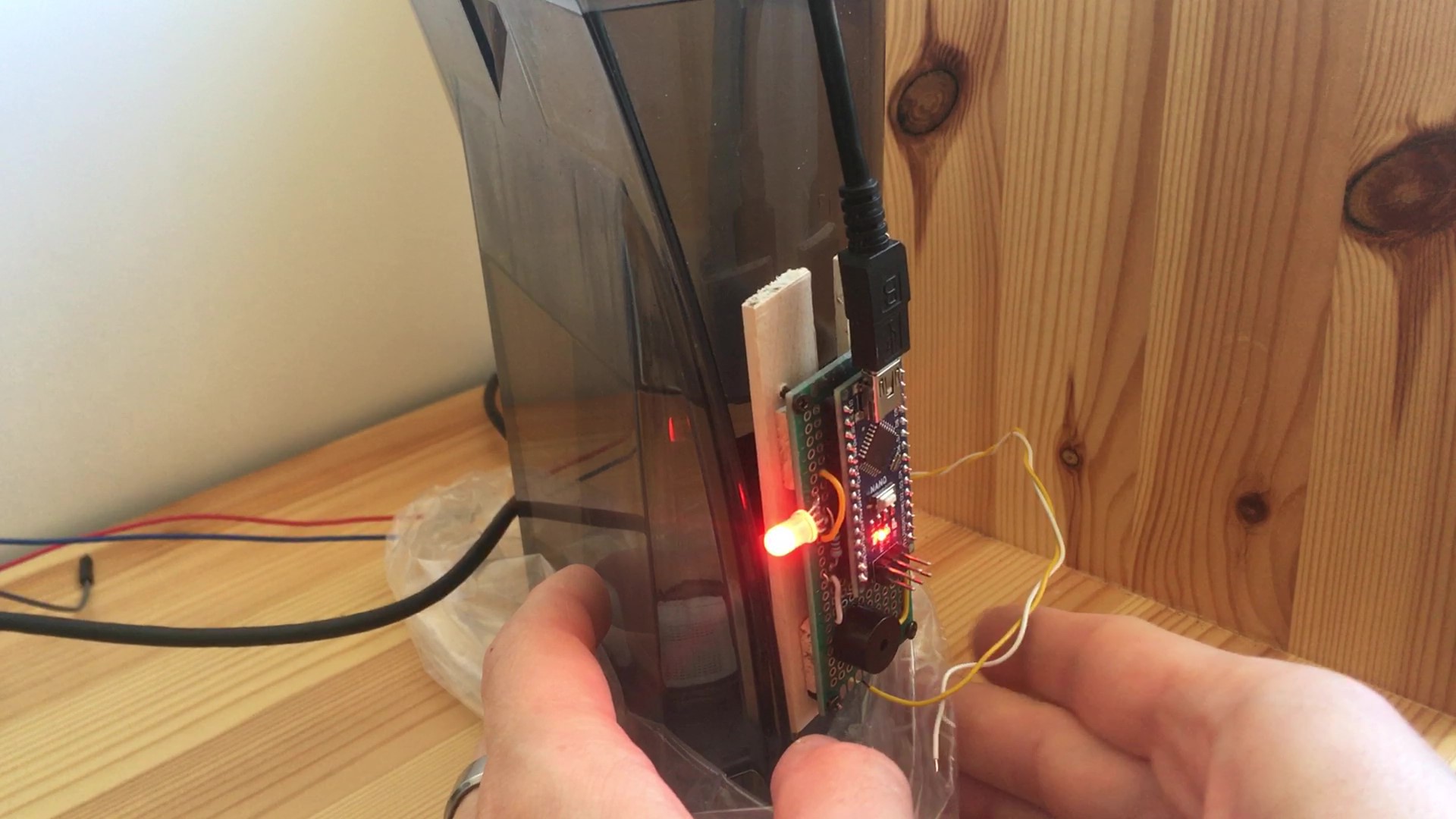
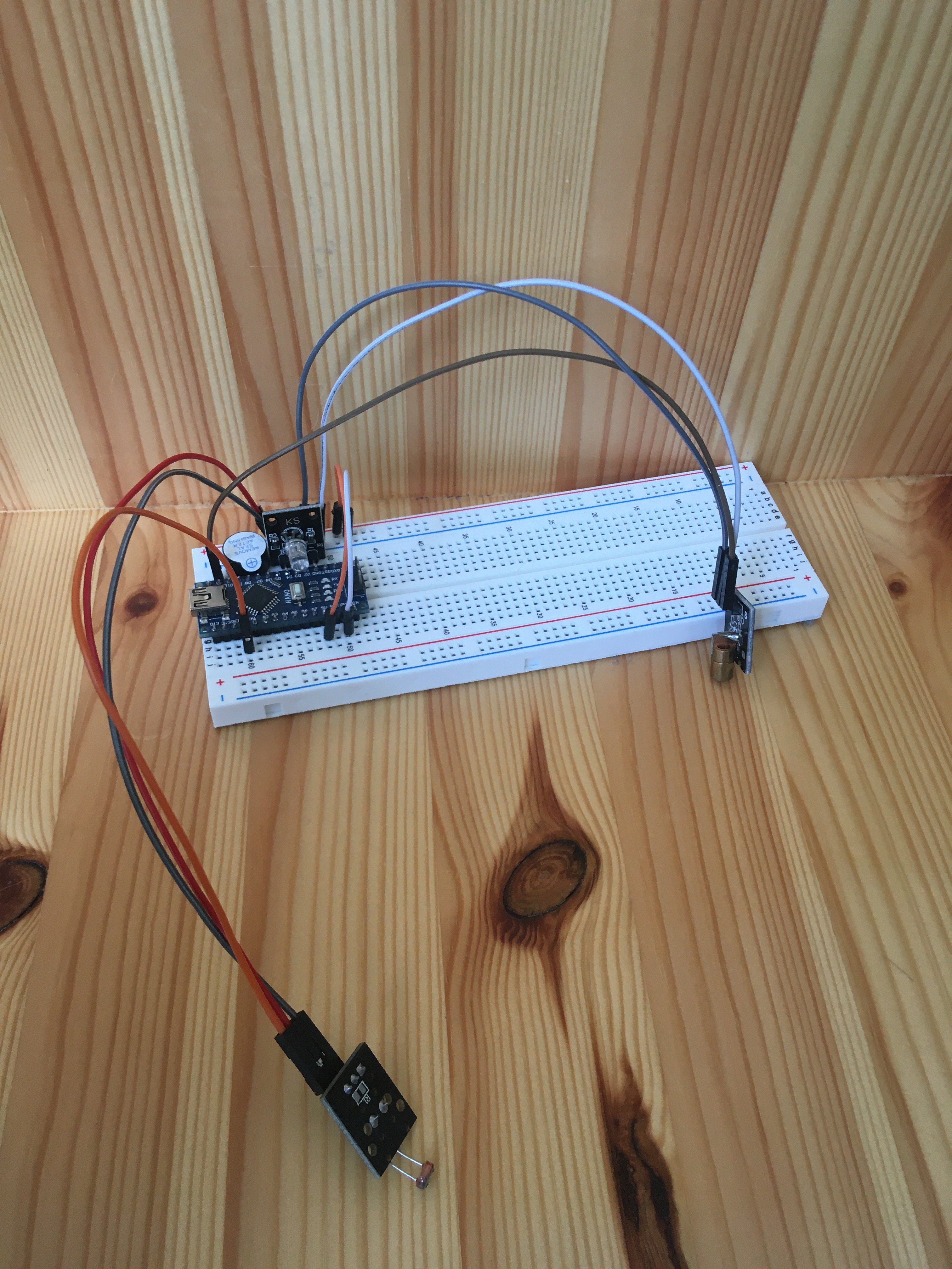
Proof of Concept
05/08/2020 at 12:41 • 0 commentsFirst I wanted to show that the concept I thought of works. To do that, I hooked up the laser diode and photoresistor from my sensor kit to an Arduino Nano on a breadboard.
Testing components
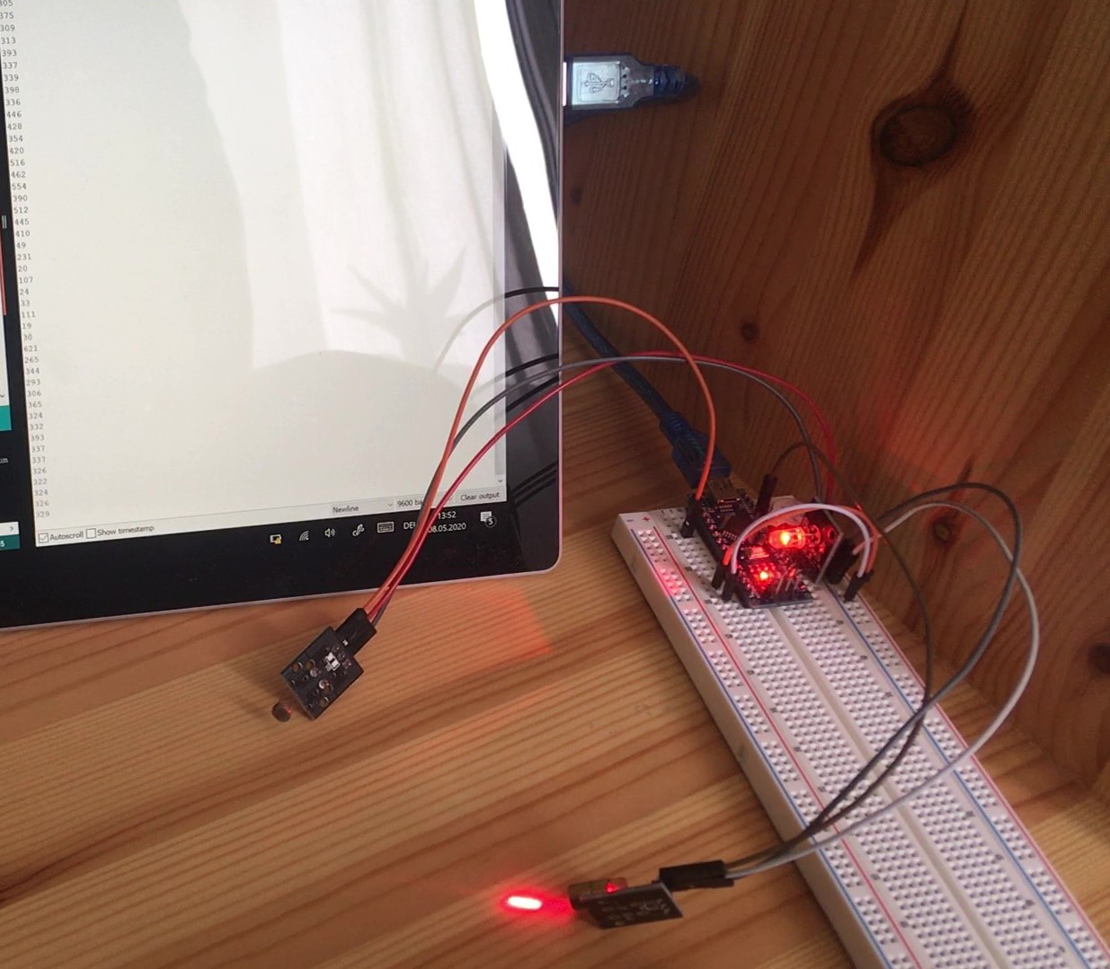
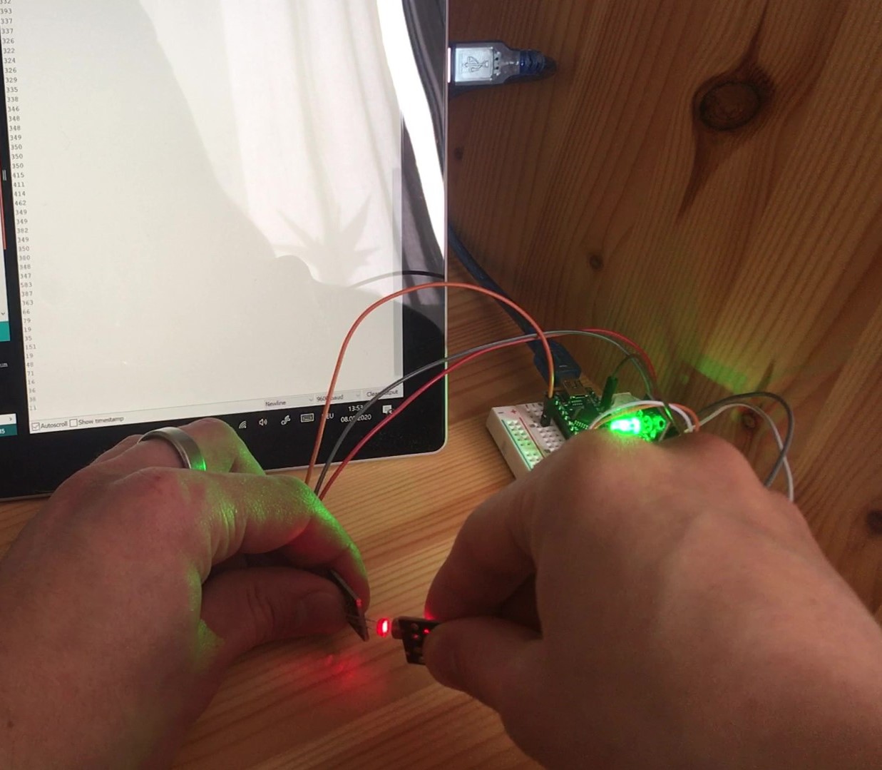
I detected the changing resistance when the laser hit the photoresistor and when it didn't. I added a RGB LED and an active buzzer as alarm signals and wrote some code for my Arduino. Now the LED turned red when the laser didn't hit the sensor and green when it did. Changes were accompanied by some buzzing sounds.
To make things clearer, I changed the buzzing sound to a high-pitched beep when the laser didn't hit the sensor anymore (water needs refill!). When it hit the sensor again (water is refilled), the LED blinks blue three times with electronic buzzing to indicate that everything is OK now.
![]()
![]()
![]()
Testing application
Next up, I tested this setup on the water tank of my coffeemaker. Luckily, it worked great! When I position sensor and laser in such a way that the light hits the sensor beneath water surface, it will cease to do so above the water surface. I refined the "ON" and "OFF" thresholds for the photoresistor so that ambient light and dimming of the laser by water and plastic would be compensated.
Water level alarm for coffee maker
Non-invasive gadget that reminds me to fill up the water tank of my Caffissimo coffeemaker when water level gets too low