 Just4Fun
* * OVERVIEW * *
The W806 is an interesting low cost MCU made by Winner Micro. There is a page about this MCU here on Hackaday.io with a lot of useful information. Another one great source of information is a blog here. Please note that the official documentation is only in Chinese, so these pages are a great help.
The main specs of the W806 are the following:
- 32-bit XT804 processor
- frequency up to 240MHz
- built-in DSP, FPU and security engine
- Built-in 1MB Flash
- 288KB RAM
- Integrated PSRAM interface, supports up to 64MB external PSRAM memory
- 6-channel UART high-speed interface
- 4-channel 16-bit ADC, the highest sampling rate is 1KHz
- 1 high-speed SPI interface (slave interface), supports up to 50MHz;
master/slave SPI interface
- 1 SDIO_HOST interface, supports SDIO2.0, SDHC, MMC4.2;
1 SDIO_DEVICE, supports SDIO2.0, the maximum throughput rate is 200Mbps
- 1 I²C controller
- Integrated GPIO controller supporting up to 44 GPIOs
- 5 channel PWM interface
- 1 Duplex I²S controller
- LCD controller, supports 4×32 interface
- 15 Touch Sensors integrated.
This MCU caught my attention, so I decided to make a board with the layout of an Arduino Mega and called it Azz!Duino.
More, as the W806 uses a QFN-56 package with a pitch of 0.35mm, it was a good occasion to put "under pressure" my soldering skills...
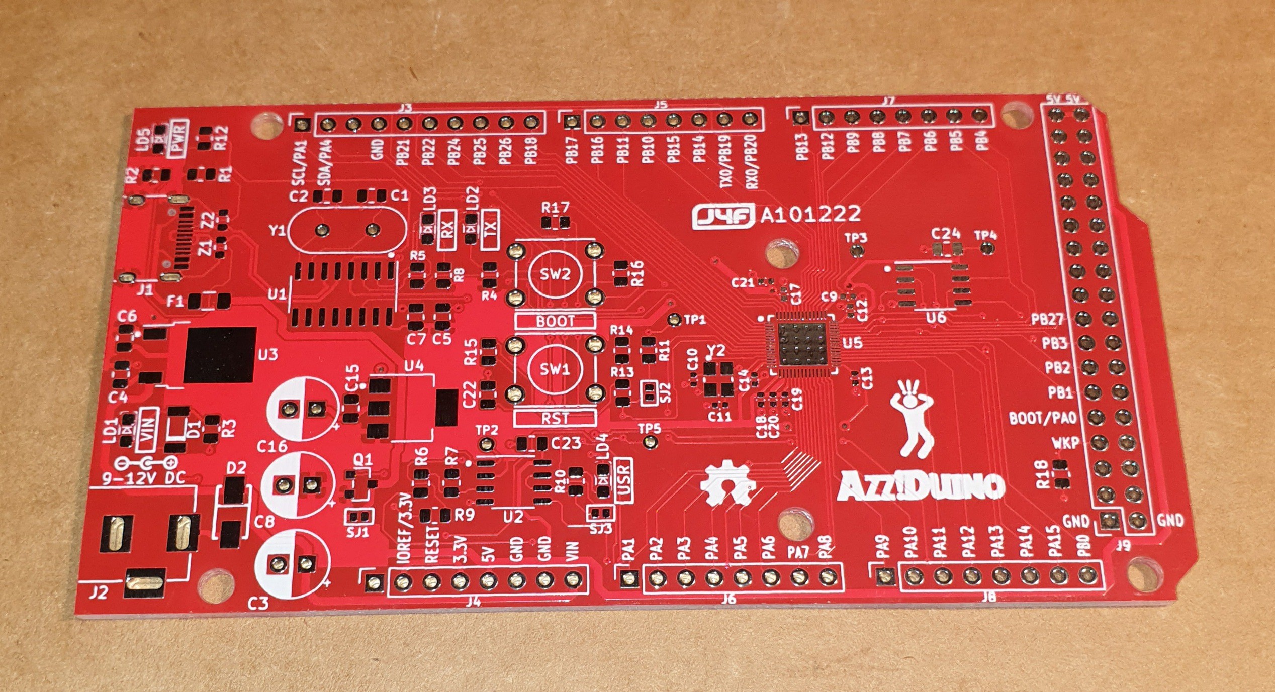
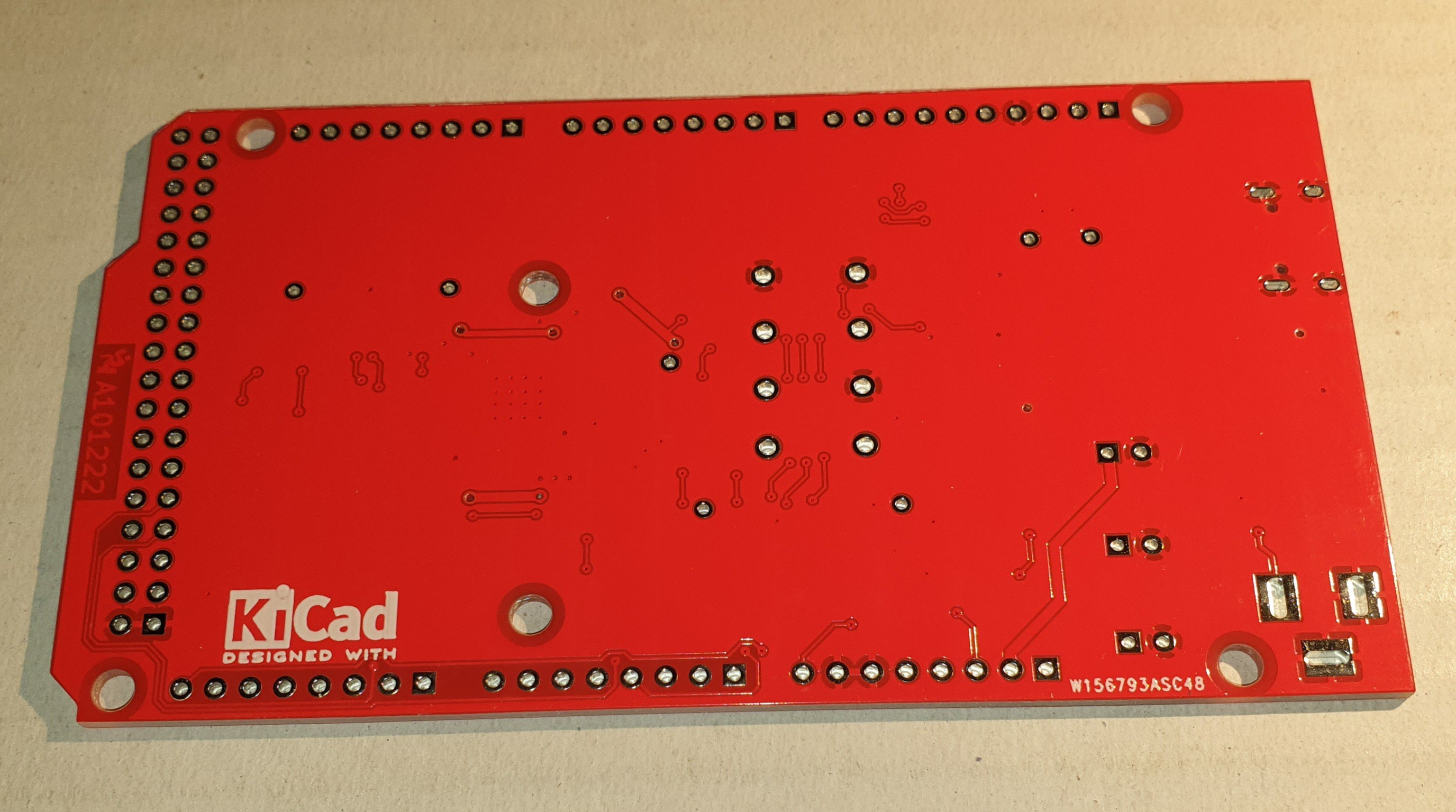
In the following images the 2-layer PCB:
* * SETTING THE PCB HW OPTIONS (SJ1/3)* *
The PCB allows two assembling options (see the schematic in the Files section):
- the EXTPWR option for an auxiliary power input as commonly available on the various Arduino boards;
- the PSRAM option to add 8MB to the RAM address space of the MCU.
In the BOM file you can see the optional components setting the option you want.
Please note that if the EXTPWR is not populated you have to close the SJ1 and SJ3 solder jumpers.
WARNING!: to avoid potential permanent damages you have to close the SJ1 and SJ3 solder jumpers only if the EXTPWR option is not populated!
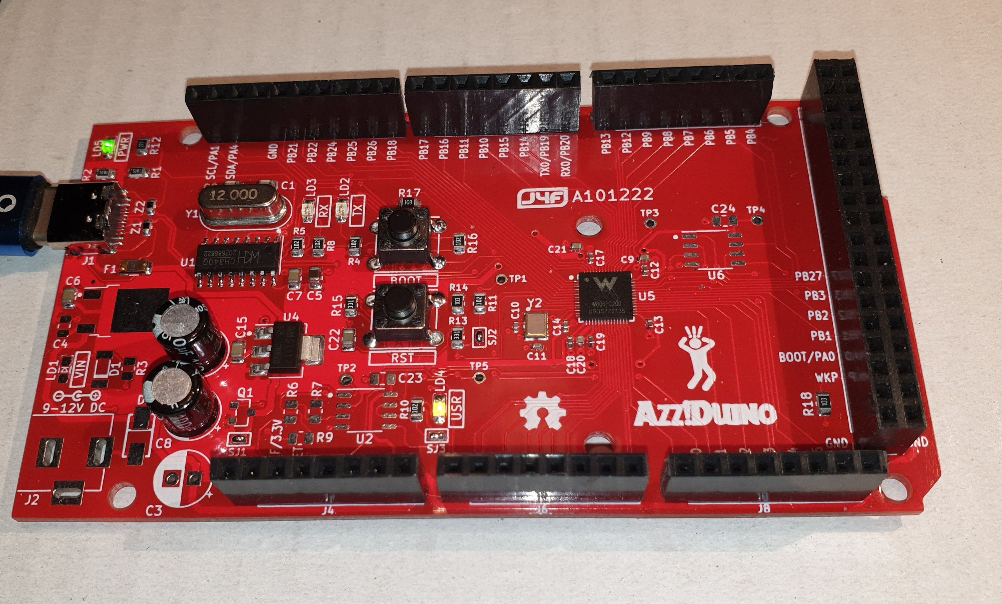
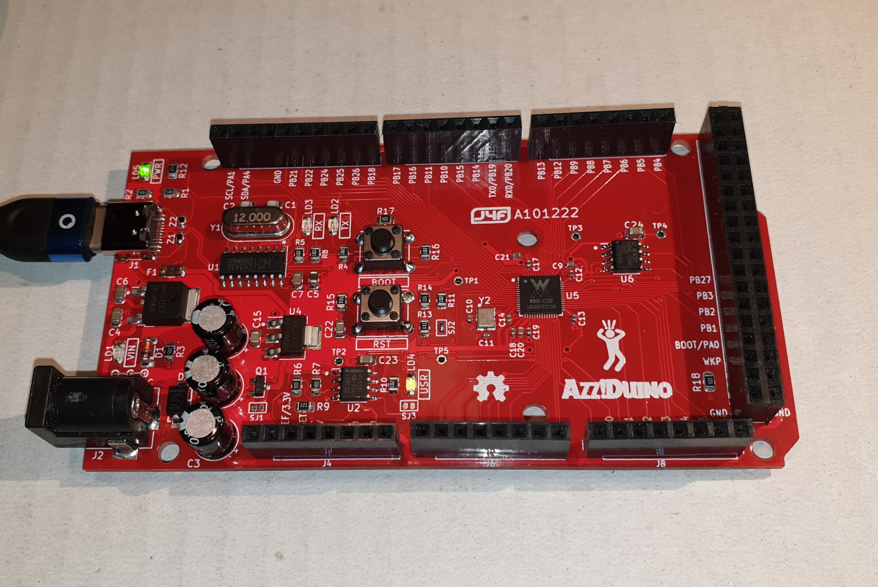
In the following images the Azz!Duino with the minimal HW configuration (both EXTPWR and PSRAM options not populated) and with all the options populated:
* * THE AUTORESET SOLDER JUMPER (SJ2) * *
To enable the "autoreset" feature driven with the RTS signal (from the serial-USB link) and used to enable the automated upload with Arduino IDE, you have to close the SJ2 solder jumper.
If the SJ2 solder jumper is open the only way to activate the internal bootloader is the BOOT key (see the * * THE BOOT KEY * * paragraph) or the RST key (the W806 internal serial bootloader is also activated soon after a reset if an ESC char is received from the UART0).
* * THE BOOT KEY * *
The BOOT key allows to manually activate the internal serial bootloader: you have to hold down the RST key, then press the BOOT key and release RST holding down the BOOT key.
When in bootloading mode the MCU sends C ASCII characters to the serial (@115200 bps).
The BOOT key can be also used as an User key when the MCU runs normally.
* * CONFIGURING ARDUINO IDE * *
There is an Arduino core for the W806 MCU that can be found here (works on Windows only).
The core is quite incomplete, but in any case can be an easy starting point to play with this MCU (of course forget to use any ready made Arduino library with that...).
To install it you just have to add the following string:
https://cdn.jsdelivr.net/gh/Hi-LinkDuino/w80x_arduino/package_w80x_index.json
in the File -> Preference setting of Arduino IDE, and then search and install from the Board Manager the W80x_arduino core. Then you can select it and download/install it as usual from the Boot Manager of Aduino IDE.
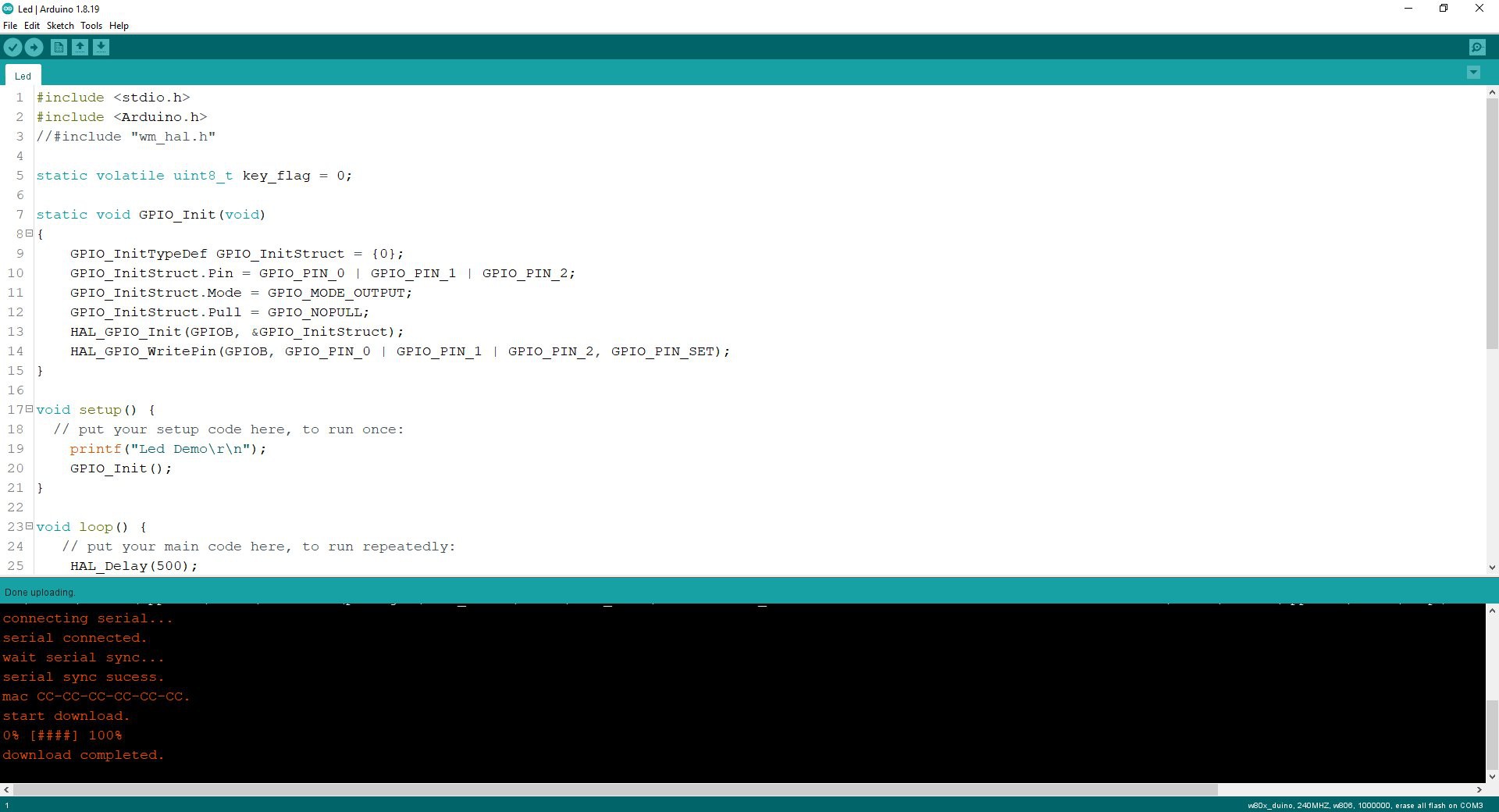
At this point there are two little modifications to the "core" to enable automatic upload (without the need to press any button on the board) and to avoid to "freeze" the board when the Arduino Serial Monitor is in use (as it activates the RTS signal used to reset the board).
NOTE: you have to close the SJ2 solder jumper to enable the automated upload mode.
FIRST MOD:
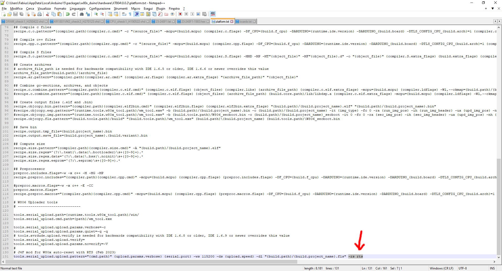
You have to modify the platform.txt file inside the Arduino IDE local folder (in my system is located at "C:\Users\<UserName>\AppData\Local\Arduino15\packages\w80x_duino\hardware\XT804\0.0.2", so adapt the path to your system), adding the -rs rts option to the following line (it's the last one):
tools.serial_upload.upload.pattern="{cmd.path}" {upload.params.verbose} {serial.port} -ws 115200 -ds {upload.speed} -dl "{build.path}/{build.project_name}.fls"
as shown in the following screenshot:
SECOND MOD:
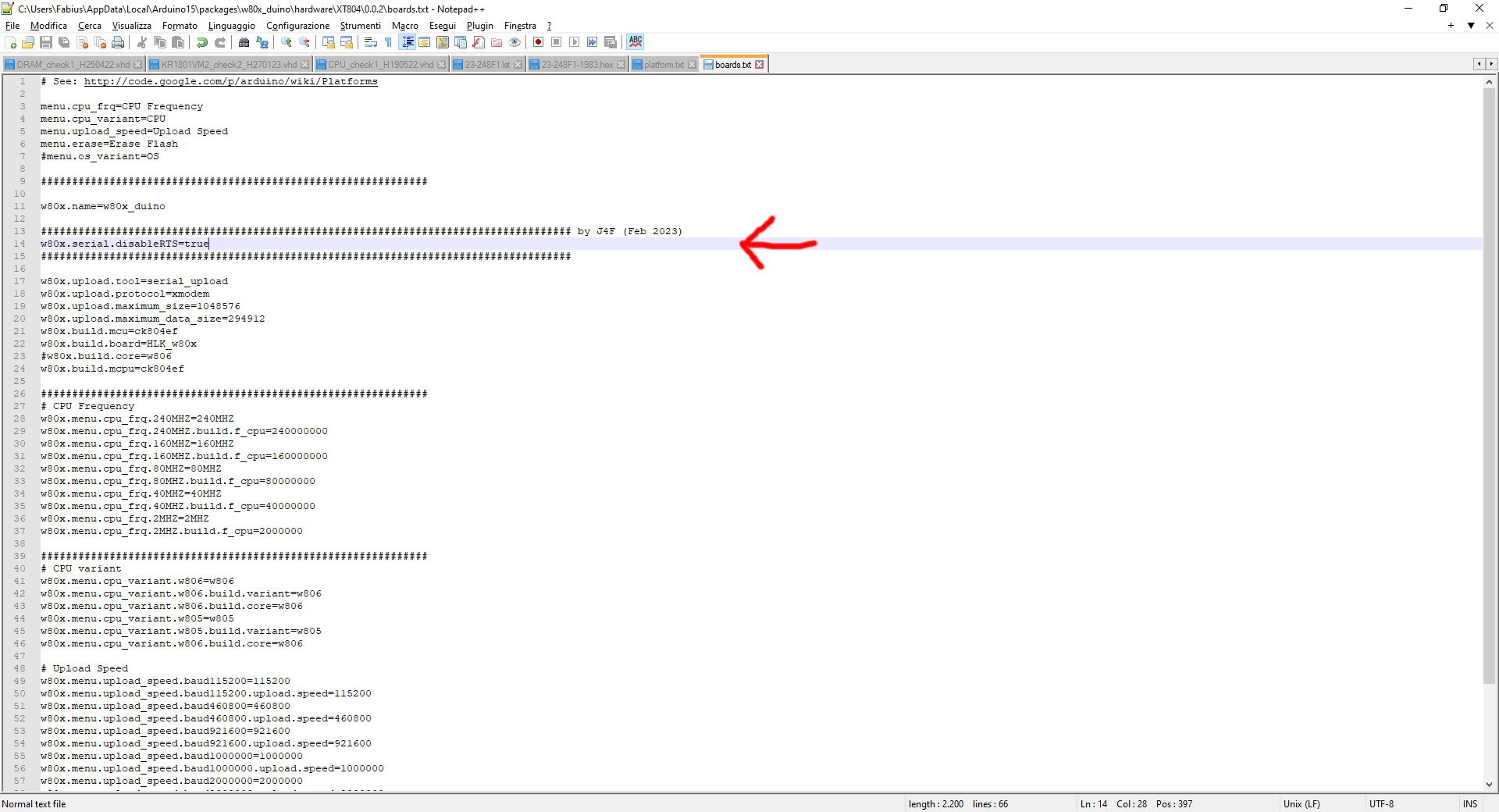
Add the line "w80x.serial.disableRTS=true" just after the line "w80x.name=w80x_duino" in the boards.txt file inside the Arduino IDE local folder (in the same folder of platform.txt) as shown in the following screenshot:
Now close Arduino IDE (if open) and re-run it. All done!
* * THE PSRAM * *
The W806 MCU allows to expand the internal RAM space address using an external 64Mbit PSRAM. In the following image the address range used to access the PSRAM contents:
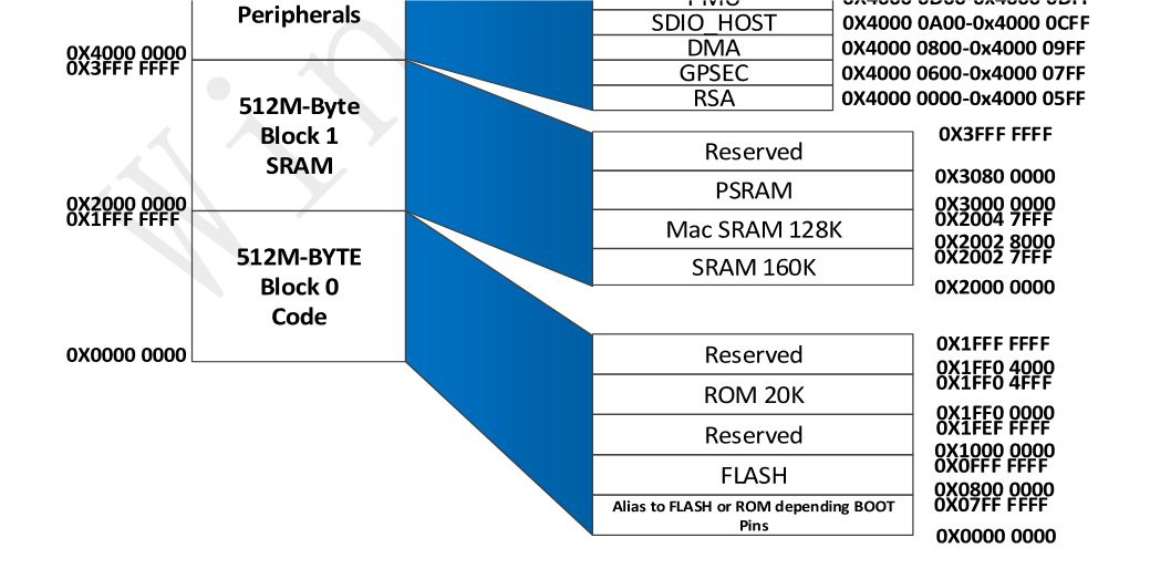
The address space reserved to PSRAM is in the range from 0x30000000 to 0x30800000 (equivalent to 0x800000 bytes = 8MBytes). When the PSRAM is active reading or writing inside that range will behave like "normal" RAM, as all the operations to write/read to/from the PSRAM are managed by the PSRAM controller HW transparently.
The maximum frequency supported for PSRAM access is 80MHz, and can be selected with a field inside the PSRAM controller registers. It is a 4bit divider for the PSRAM clock that can be set in the range [0x3..0xF] , where 0x3 corresponds to the maximum 80MHz PSRAM clock (240MHZ / 3 = 80MHz).
More, the PSRAM controller can work as SPI or QSPI. Of course the QSPI is the fastest mode.
The documentation and the SDK are both misleading about the use of the PSRAM controller, so it was not easy understand how setup the MCU.
To use the PSRAM you have to configure:
- the GPIO pin set "linked" to the PSRAM controller (the are two possible set of GPIO to choose);
- the registers of the PSRAM controller (PSRAM chip reset, clock setting, SPI/QSPI setting).
I've uploaded in the Files section a demo of the PSRAM usage (with comments).
* * WHERE TO GET A PCB * *
I've prepared an "easy" link to get a small lot (5 pcs minimum) of the Azz!Duino PCB. The link is this one.