Peter
Peter-
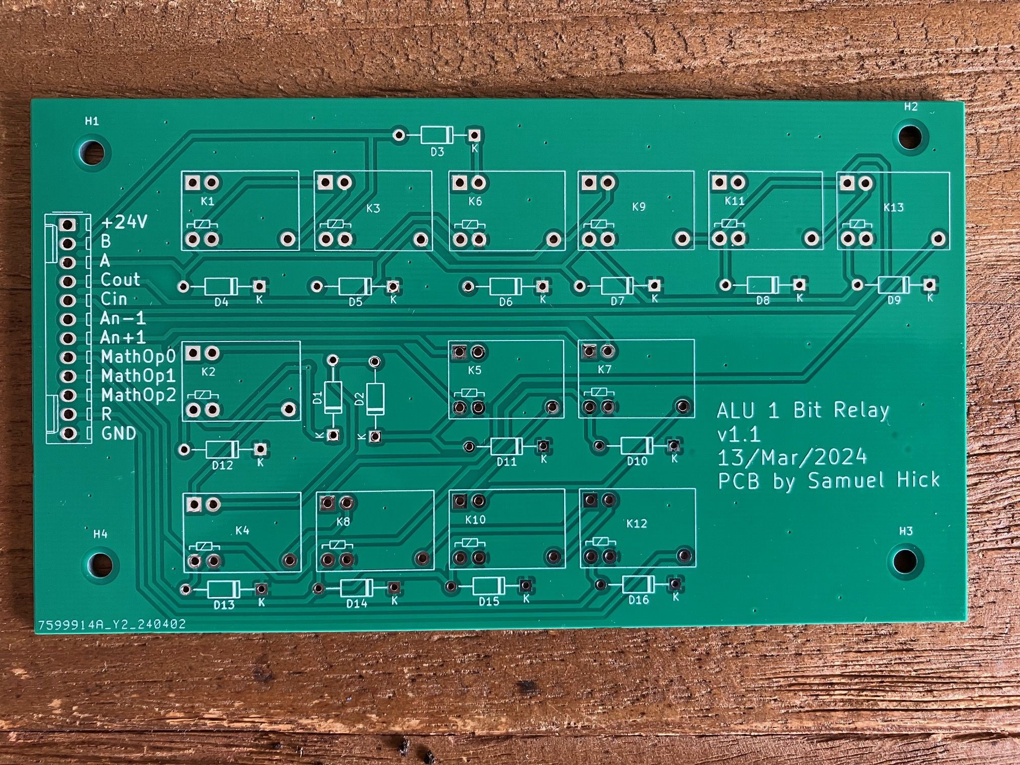
ALU PCB finished!
04/09/2024 at 13:27 • 0 commentsFor the system I need a circuit with 13 relays for each bit of the ALU...16 times the same circuit! Building this connection by connection wouldn't be a very enjoyable task. So, a friendly colleague offered me to design a PCB out of my circuit diagram. I am truly very grateful to him for it.
And this is the result. It only took 1 week from the purchase order to the delivery:
![]()
-
Finished the accumulator register
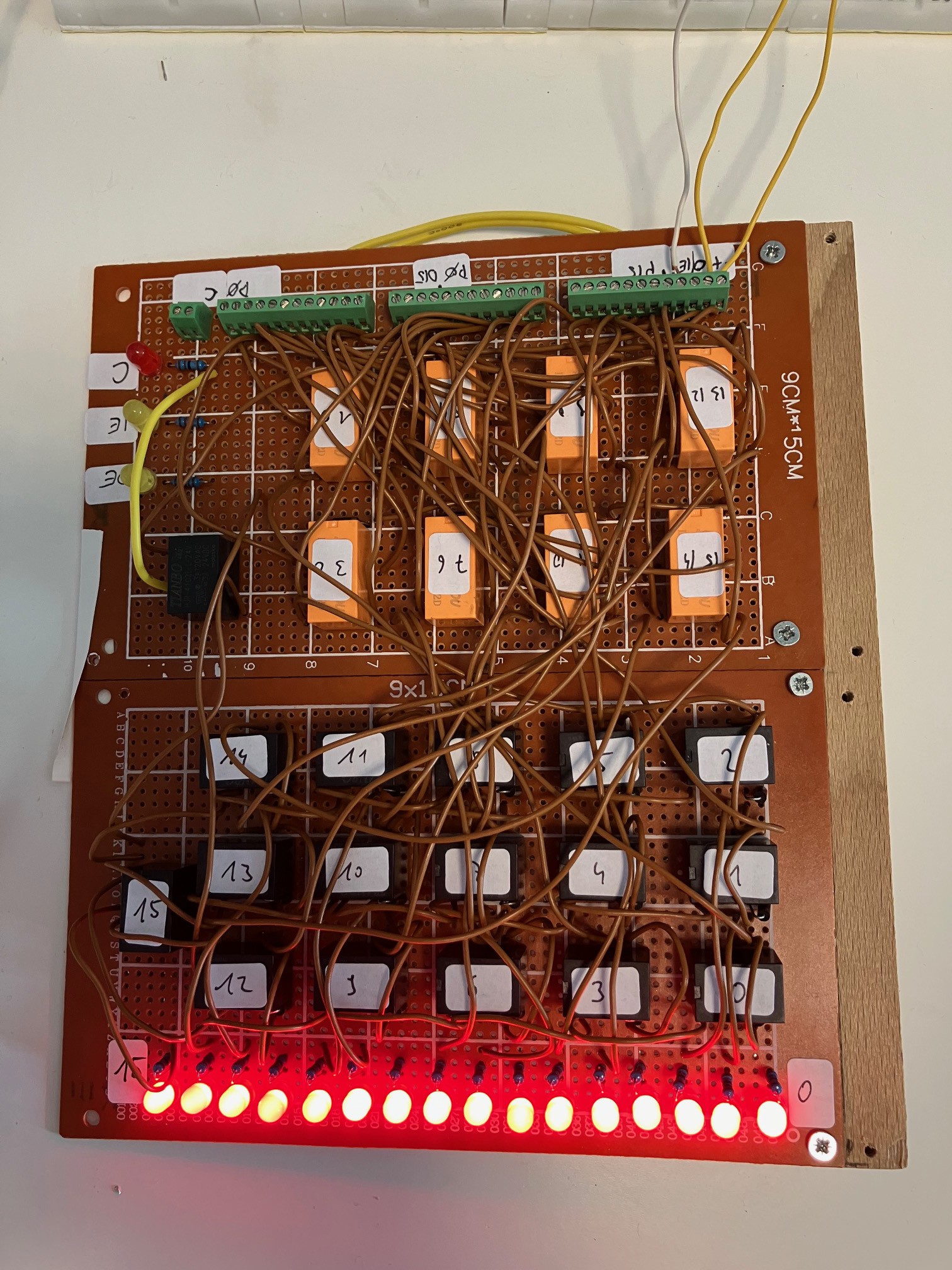
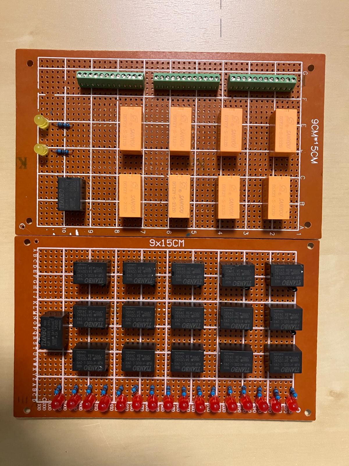
04/09/2024 at 13:10 • 0 commentsSo, the 16 bit accumulator register, which the register for all mathematical, all store and all load operations, is finished and tested. The next step is to connect the register to the system...
![]()
The 16 black relays with numbers are responsible for storing the bit values (by holding themself in an active state), the black relay without a number releases the VCC (for clearing the stored value) and the orange relays are responsible for Input and Output to/from the databus.
-
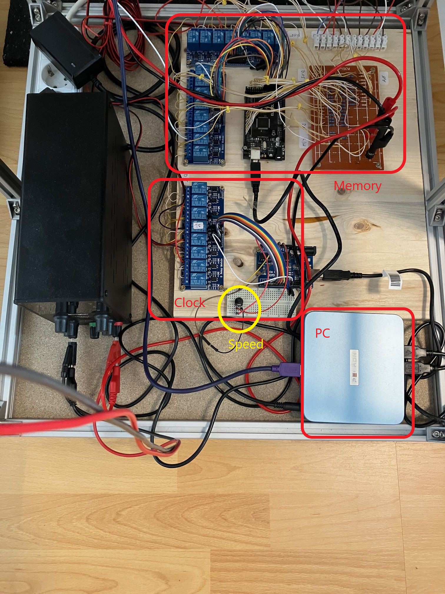
Added a little communication PC
04/09/2024 at 12:46 • 0 commentsSo, I recently added a little PC just for communication, connected to the arduinos and the logic analyzer. And reachable via remote desktop. The following picture shows you the bottom of the system:
![]()
There you see the memory, the new communication PC and the clock. The yellow marked part is a poti connected to the arduino which is responsible for the clock generation to change the speed of the system.
-
Measured the relay timings
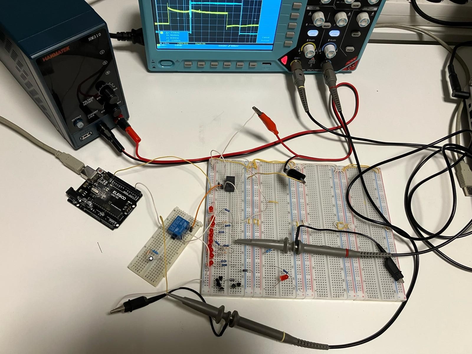
03/27/2024 at 21:41 • 1 commentSo, I measured the timing behaviour of the relay using an oszi. This was my test setup:
![]()
I used an arduino to switch on/off the blue relay (its the same type than the relay of the timing module and the memory module of the relais CPU) using the 5V of the arduino, the blue relay is using its switches to switches on/off the black relay using 24V. The output of the black relay is connected to a LED.
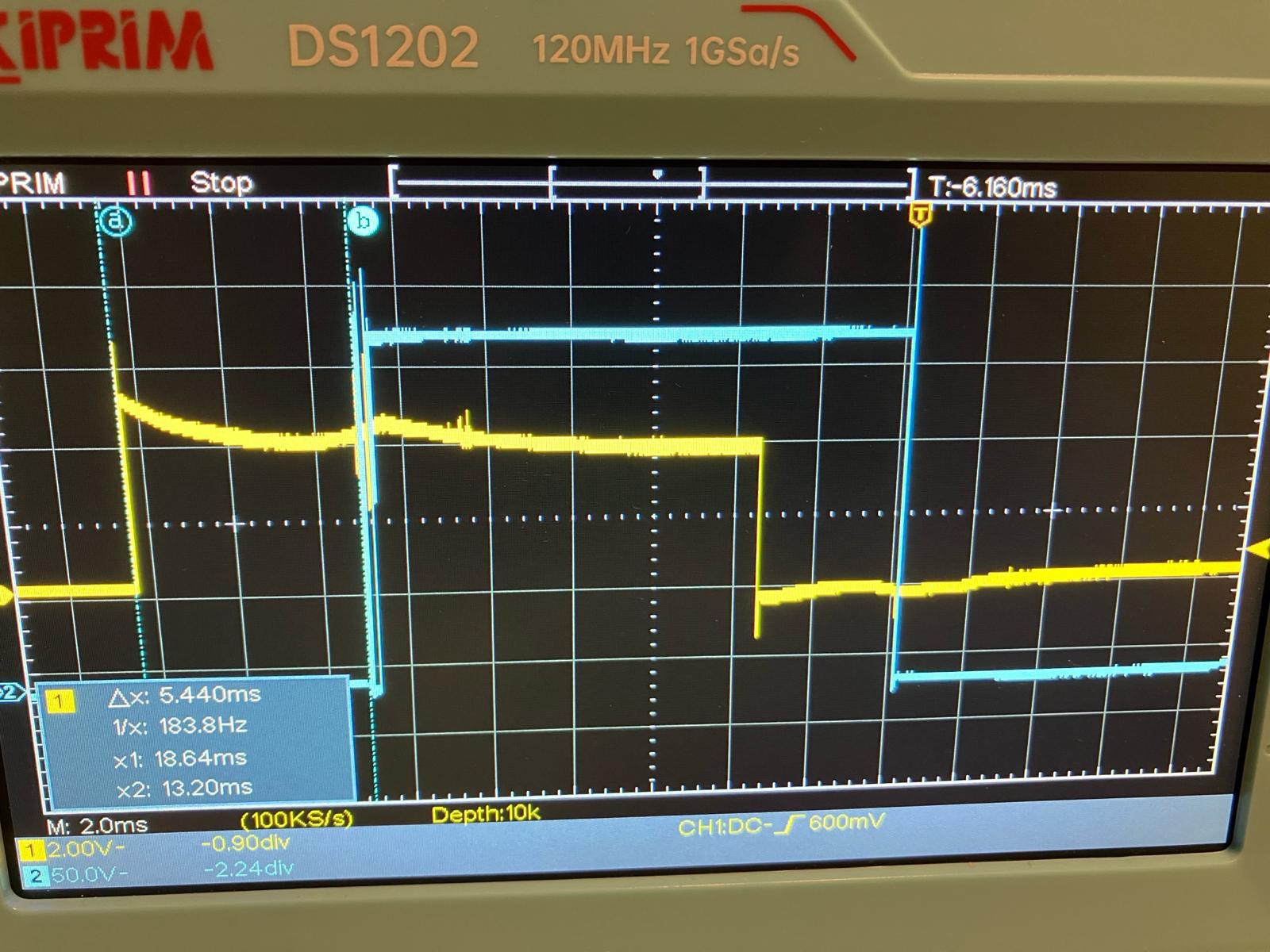
The first two diagrams show the switching of the blue relay, yellow is the arduino signal, blue the relay output:
![]()
The switch on time of the relay is 5,44ms.
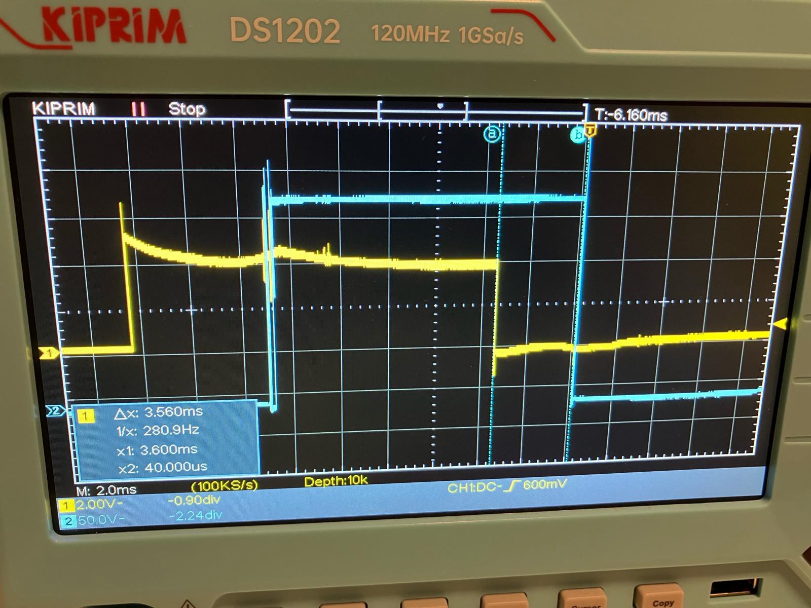
![]()
The switch off time is 3,56ms.
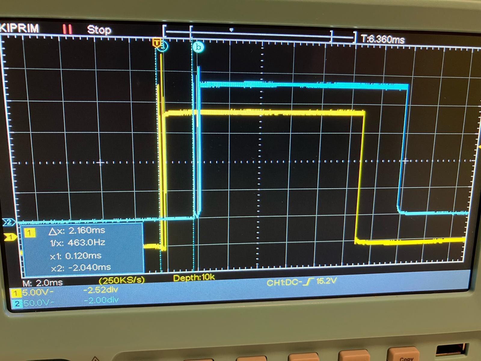
Now the measurement of the black 24V relay. which is much more important...because this is the relay which is used for 90% of the relais CPU. The blue 5V relay is only used as an arduino output for clock and memory.
![]()
The switch on time of the relay is 2,16ms, thats very fast. The bouncing of the relays is visible, but not a very big problem.
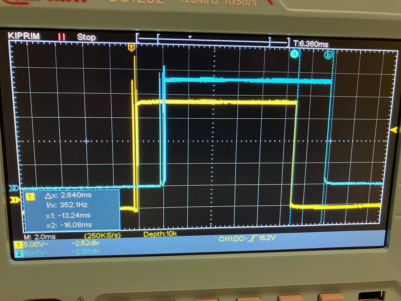
![]()
The switch off time is 2,84ms...also very fast.
Summary of the test: the used relays are faster than I thought!
-
Started the next module...the accu.
03/27/2024 at 18:47 • 0 commentsHere you see the beginning of one of the most important modules of the system...the 16bit accu:
![]()
-
Test and video with high speed
03/14/2024 at 18:30 • 0 commentsIn the following video you see the system running with high speed and out of the system memory. I replaced one of the clock relays, this improved the stability of the system a lot!
-
Changed a clock relay...
03/13/2024 at 19:26 • 0 commentsSo, as described in my last project log, I changed the relay of clock 0 (which looked a little bit bouncing). Thats the result with the oszi:
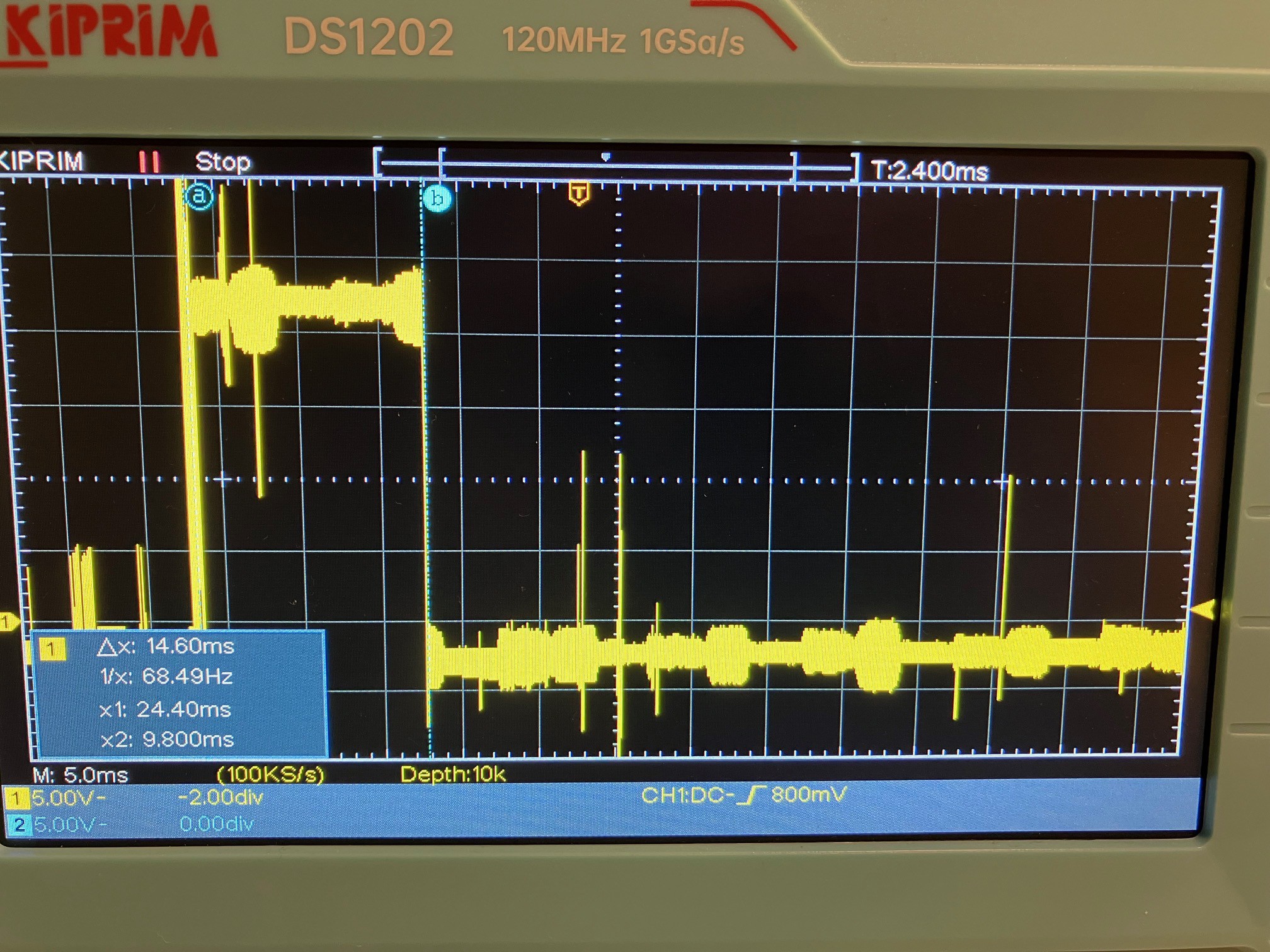
![]()
The signal looks much better than before. And the CPU was running with this speed (14,6 ms compared to 27 ms) for minutes without crashing. No, thats not a proof that the clock 0 signal quality was THE reason of the crashes with higher speed, but the bad signal quality before was possibly A reason...
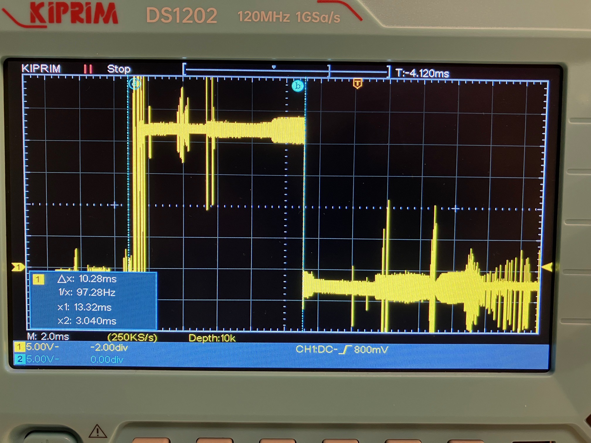
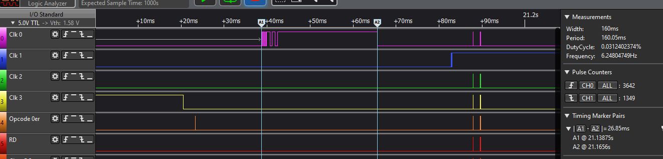
And after that success I wanted to know how fast the system now is able to run. That was the result:
![]()
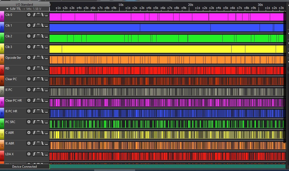
The system was running very stable with a very high clock speed, clock 0 was down to 10 ms...the next two pictures show you the logic analyzer pictures:
First an overview, the measure time is 33 sec, but the system was running for a longer period:
![]()
And a detailed view:
![]()
Maybe I reached a stable situation and the system timing and the memory software is...not perfect yet, but OK.
-
Timing measurments
03/12/2024 at 17:23 • 0 commentsIf only the control unit was running, receiving the opcode of a command directly from the arduino which generates the clock signals, the timing of the system was very fast. A NOP command was finished within 128ms.
But the connection of a memory based on a arduino changed the situation. Now the timing is more difficult...and I tried to figure out what is happening, because the system now runs perfect with high speed and sometimes, could be after 10-20 commands, it crashes.
The following tests were made with a slower speed, the system was running very stable, without any crash.
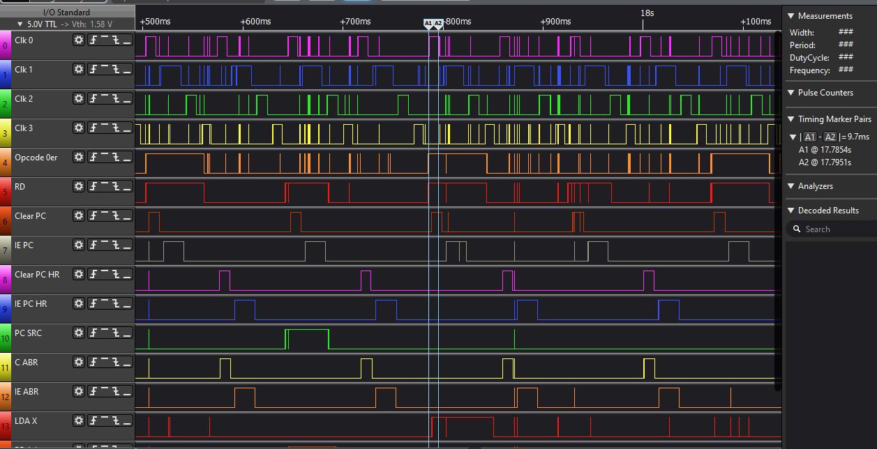
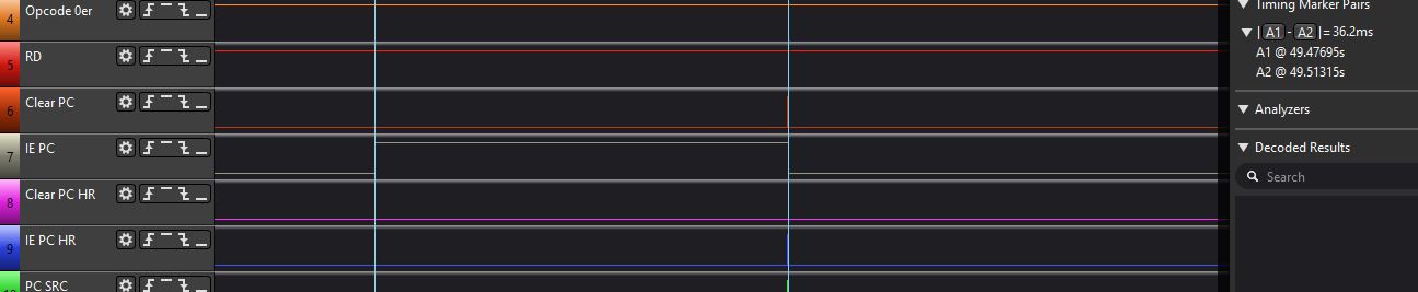
Here you see a logic analyzer picture of Clock 1:
![]()
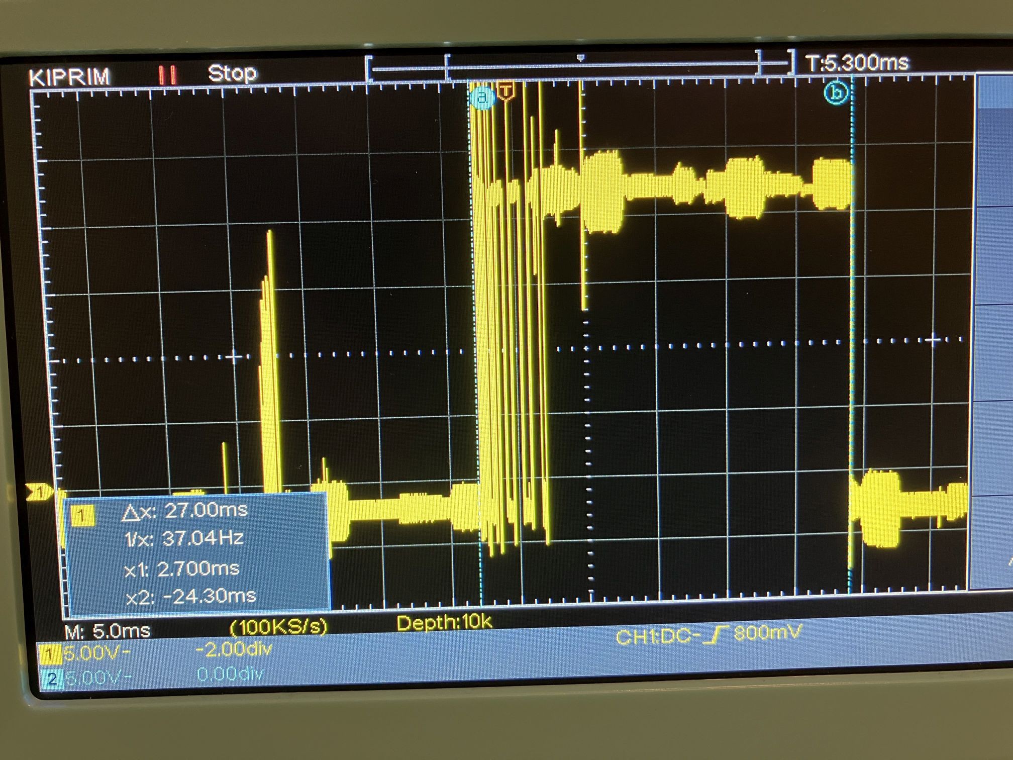
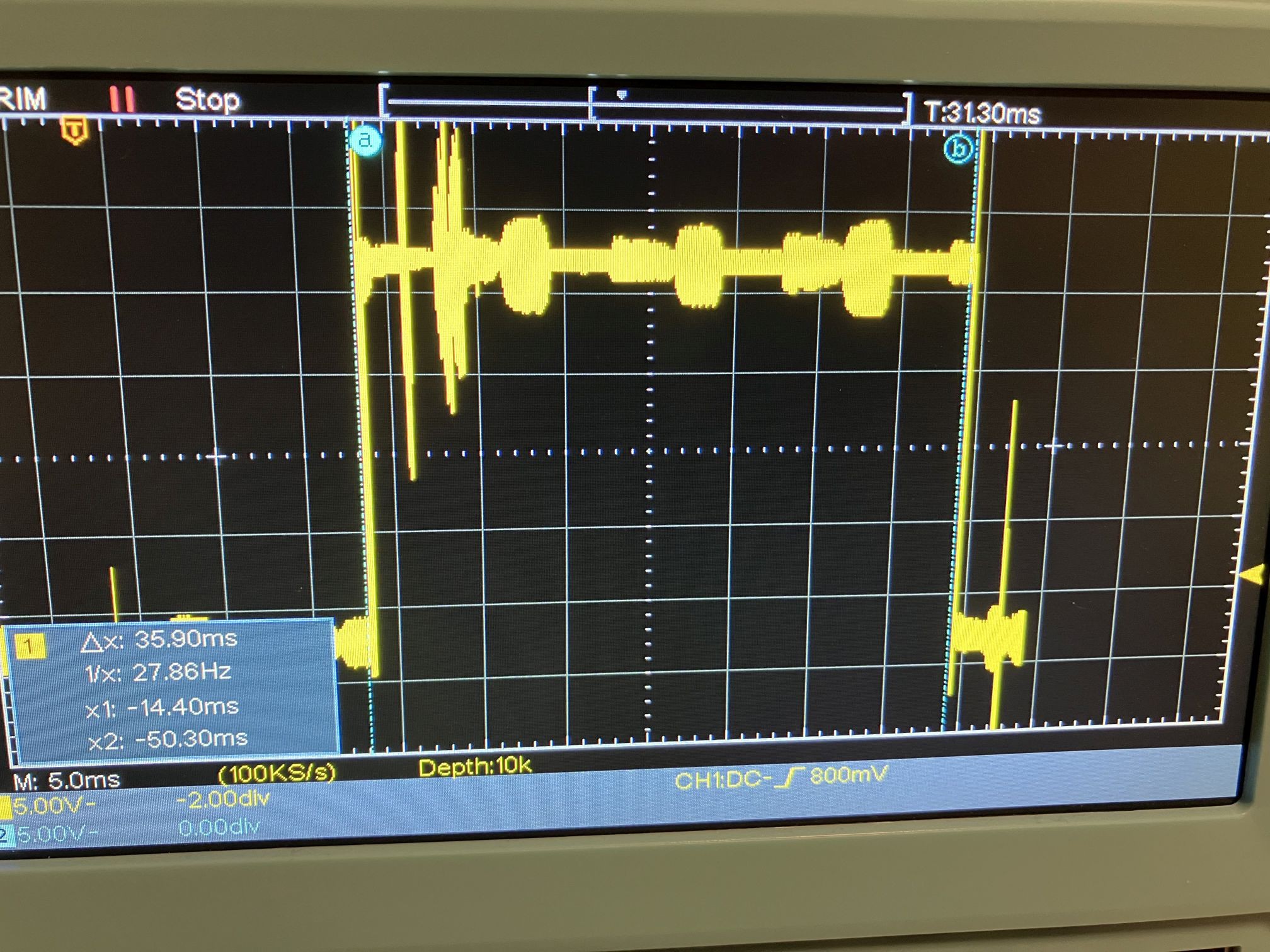
You see a interesting thing: the signal of Clock 1 looks not very good. The rising edge of Clock 2 for example looks much better. The signal time of Clock 1 was 26,8 ms, which is not very fast. The fastest Clock 1 time I tested (without a memory module) was 7ms. I was not sure if the signal realy looks that way or maybe the logic analyzer is showing something wrong. So I used a Oszi:
![]()
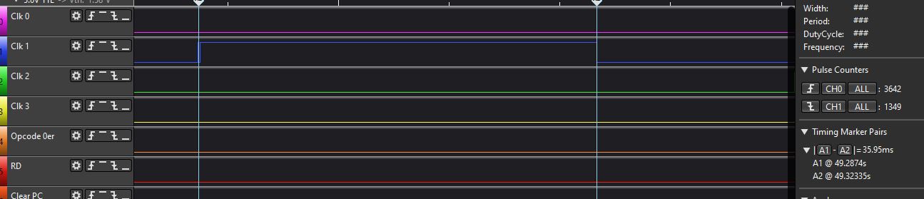
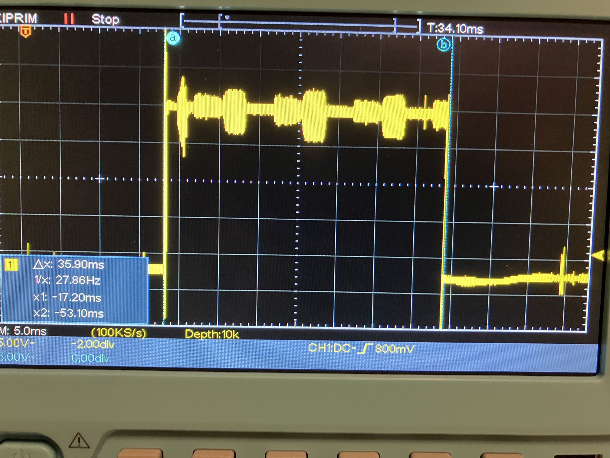
The first thing to notice: the timing measure is very accurately. The second thing: The signal does not look very good, even on the Oszi. If I reduce the signal time to 7ms no stable state will be reached. I checked another clock signal, Clock 2:
![]()
and the Oszi picture:
![]()
This Clock looks much better, in the logic analyzer and in the Oszi (Clock 2 is 10ms longer in High than Clock 1, this is correct).
The last signal I checked was the input enable of the program counter:
![]()
looks perfect in the logic analyzer. The Oszi measures:
![]()
Thats an excellent signal.
What is the result of the measurement? The relays have very different quality, and the relay generating clock 1 seems to be one of the worse relays. I will change the output relay of Clock 1 and see what happens.
-
Crash Video...
03/11/2024 at 13:38 • 0 commentsHello, the following video shows you the crash of the relay CPU...and explains the reason for the crash. I thought that the bad wiring of the system was the reason for the crash, but in reality there are 2 reasons...a) a SW bug in the arduino software, I used pow(x,y) to calculate the adress delivered by the relay CPU, this did not work as I expected and b) some timing problems in the memory module (I am still fighting a little bit with the timing, but I will explain this in a later video).
-
A big success...and some problems
03/09/2024 at 09:04 • 0 commentsYesterday, a big success happened...the system was running out of the memory. Until now, the Arduino delivering the Clock also delivered the opcode directly to the instruction register, but yesterday the CPU itself fetched the opcode by reading memory adresses using its adress module.
And then anything broke apart ;-).
The reason for the problems lies in the "quick and dirty" wiring of some modules and the connection between the modules. If testing the adress module alone: it worked fine.
So, the next days I will rewire parts of the system.
Homebrew 16 bit relay computer
Goal of the project is to develop and build a homebrew 16 bit relay computer