-
Into Production...
06/17/2015 at 23:31 • 0 commentsWell, the last few weeks have been spent in a down-to-earth kind of way: getting all the parts ready for a run of kits. And finding out that the logistics of making a kit in larger numbers are, errr, nontrivial.
All the documentation, design files and software can now be downloaded from here. The software and manual are not in their final form yet, but should be OK for a first test drive. Note that the PiDP software does not require the physical front panel to be present. It should run on any Pi.
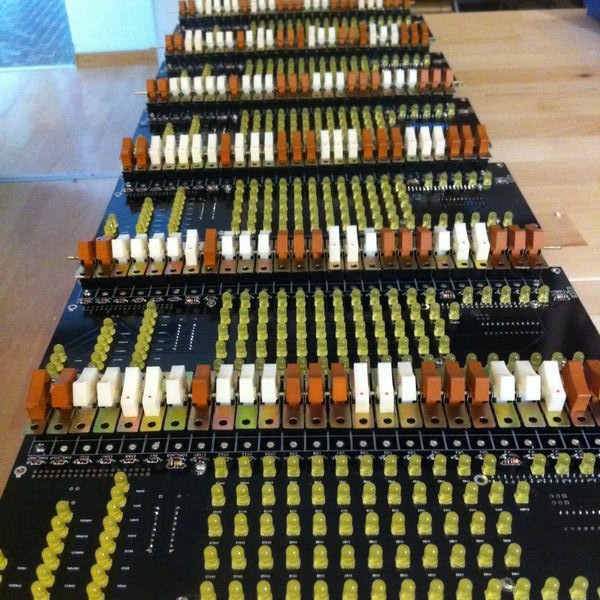
Meanwhile, a snapshot from the factory floor, some assembled kits for testing:
![]()
A few weeks of hard physical labor and the first run of kits should all be packed up and sent out. But - as a Wise Man told me before I started - doing a kit this way is pretty hard work. Not something you should do regularly. When the Wise Man told me, I knew he was right. Now it's different. I feel he is right... I'll do one more run of kits in September, then I have to look for other ways to make them. If there is still demand, that is!
-
A Real PDP-8/I
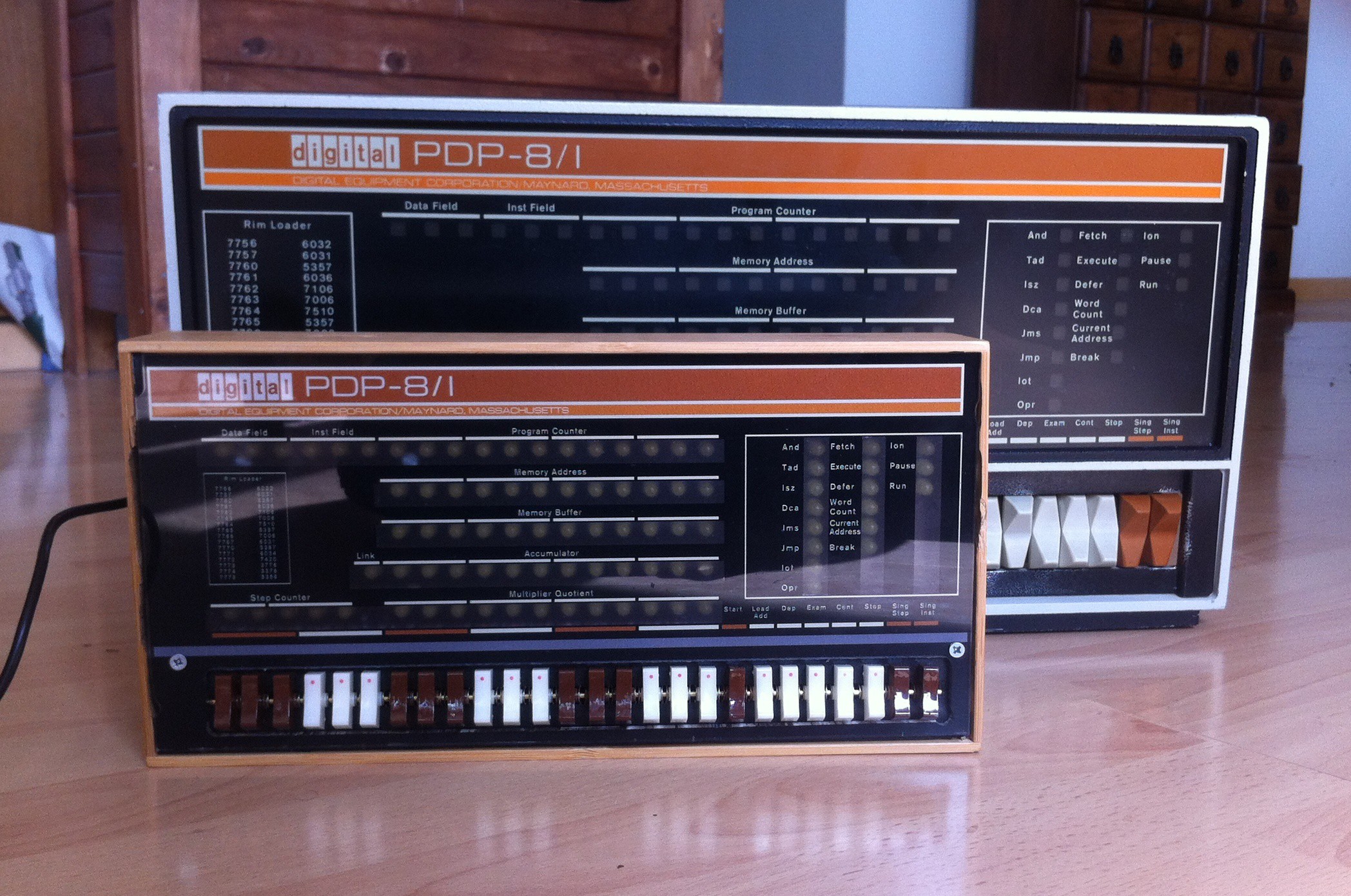
05/07/2015 at 22:31 • 5 commentsWell, the front panel of a real 8/I. I can't even remember how long I wanted one. Today was a good day. An excellent day. An 8/I FP in perfect condition found its way home to me thanks to PDP collector and expert hb9aik (saying thanks once is not enough, so thank you!). Here it is, next to the PiDP replica:
![]() This, of course, will spawn a whole new project: letting the PiDP code drive the real panel. But first, the PiDP replica needs to be finished. Risk of distraction :)
This, of course, will spawn a whole new project: letting the PiDP code drive the real panel. But first, the PiDP replica needs to be finished. Risk of distraction :) -
At VCF Europe (2-3 May)
05/01/2015 at 21:17 • 0 commentsWell, VCF East X was great fun. Learned a lot, and also left 3 PiDP-8 prototypes in the hands of - hopefully - nastily critical betatesters.
![]()
Just back from there, I'll be going to VCF Europa in Munich this weekend.
Afterwards, it's time to polish up the software a bit, and prepare for a run of kits. If you're (seriously) interested, please sign up for the mail list here (link). I'd like to have an estimate of how many people are seriously interested so I can plan how many parts to buy for a batch in mid-July.
-
Ready for the VCF East, April 17-19
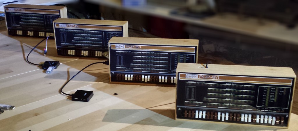
04/10/2015 at 23:42 • 0 commentsWell, there they are, the four prototypes:
![]()
I played around a bit with connectivity options. So two PiDPs use a Raspberry Pi Model A+, the other two a Model B+. The machine in front has a slot on top to access the HDMI monitor connector (slot not necessary with the right HDMI cable, BTW), the other machines only run terminals from serial or network terminals which is all you need.
- The Model A's have the serial port enabled (meaning R23&24 were clipped off from the Pi's).
- To connect a modern laptop, use a USB-to-TTL-Serial cable. A neat plug & play solution without need for a power supply: the PiDP runs happily off its 5V power pin.
- To hook up a vintage serial terminal, you need a TTL Serial-to-RS232 converter, and a 5V power supply (or a laptop's USB port).
- All PiDPs have a micro WiFi adapter plugged in, so you can log in to PDP terminals that way too - or use WiFi with VNC to run the Pi's desktop GUI concurrent with the PDP-8 terminal...
My better half has decided that our suitcases will be filled with more important things than PiDPs on the way back home from VCF East. Like shoes, I presume. So if you're at the VCF and want to take one of these PiDPs, please let me know :) They are 100% compatible with the future final version of the board, they just have some manual fixes on the PCB. - The Model A's have the serial port enabled (meaning R23&24 were clipped off from the Pi's).
-
Demonstration run on Youtube
03/30/2015 at 22:37 • 2 commentsI finally got round to making a Youtube movie of the PiDP in action: http://youtu.be/5hyUActgT2E
Some points to note though:- I still have to verify all the LEDs respond exactly as they do in the real 8/I - I believe so but the real test is at the VCF East!
- You'll note that those switches that are momentary toggle switches in the original are still 'flick on/flick off' in this prototype. I'm planning to put some springs in these switches to make them momentary - it's not hard to do. But to be honest, you get used to this so quickly it's not very high priority. The front panel software converts a on/off toggle into a momentary signal anyway.
- Also, the STOP switch is meant to be upside down from all the other switches (off = down). I let it be inversed - off = up - for the moment, it's a setting in the code but I prefer it this way myself.
- This particular PiDP uses a Raspberry Model B+, so it has a slot in its side to let out all the connectors. But using a Model A+ is both cheaper and more elegant. You can establish a terminal session through ssh on the network, or hook up an old serial terminal. The advantage of ssh, of course, is that you can hook up multiple terminals that way. Although I still have to test that!
-
Prototype finished!
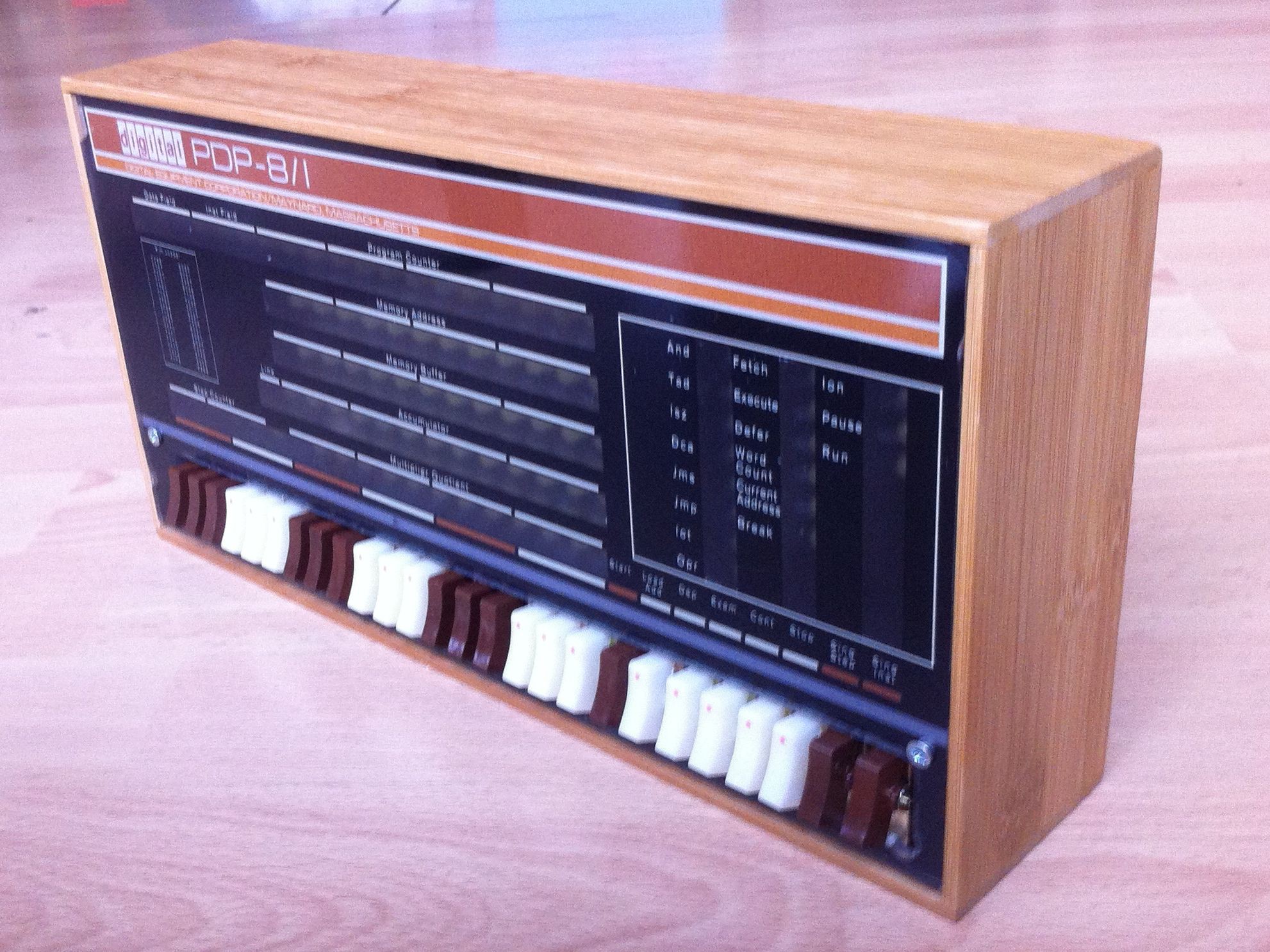
03/22/2015 at 19:19 • 0 commentsDone! Case, PCB and acrylic panel are put together for the first time to make my replica PDP-8/I...
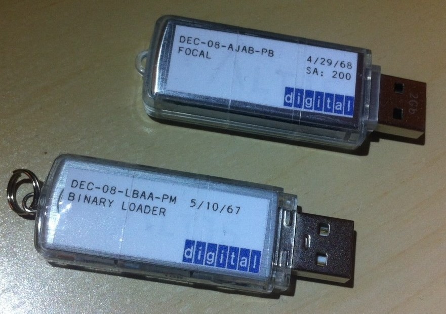
![]() It turned out exactly as I had hoped, so very happy. Well, almost exactly. It's the first of the four prototypes I ordered parts for, and I made a few mistakes handling the router. But who cares. Below is a picture of the PiDP-8 with its all-in-one peripheral: a USB hub of which one slot is the PTR (shown with two faux paper tapes, the BIN Loader and Focal69), two slots are disk drives, and the fourth is a removable disk cartridge.
It turned out exactly as I had hoped, so very happy. Well, almost exactly. It's the first of the four prototypes I ordered parts for, and I made a few mistakes handling the router. But who cares. Below is a picture of the PiDP-8 with its all-in-one peripheral: a USB hub of which one slot is the PTR (shown with two faux paper tapes, the BIN Loader and Focal69), two slots are disk drives, and the fourth is a removable disk cartridge.
So now for wrapping up some small details, and after the Vintage Computer Festival East X in mid-April, where my faux PDP will get its baptism amid some Real Stuff, I'm planning to make a kit out of it. This has been so much fun...![]()
-
Polishing up the software
03/20/2015 at 23:48 • 0 commentsBecause the PiDP is just a physical front end for simh, it inherits the rather useful step-out-of-emulation abilities of simh. But mounting a paper tape through the emulator's command like is not very replica-like. It is, in fact, decidedly unromantic.
So I made it such that you take a USB stick, put a disk image or paper tape image on it, and then you stick it in to the machine. You hit the SING_STEP and SING_INST switches at the same time, and whatever image is on the stick is auto-mounted.
The nice thing is that now, USB sticks are just modern replacements for paper tapes or disk cartridges! The form factor is different, but plugging in the BIN Loader stick and hitting the two switches does exactly the same as putting a paper tape into the paper tape reader and powering the device on. It's great fun! (I think).
![]() More details on the blog page (link), including some further software developments.
More details on the blog page (link), including some further software developments. -
Acrylic panel sent off
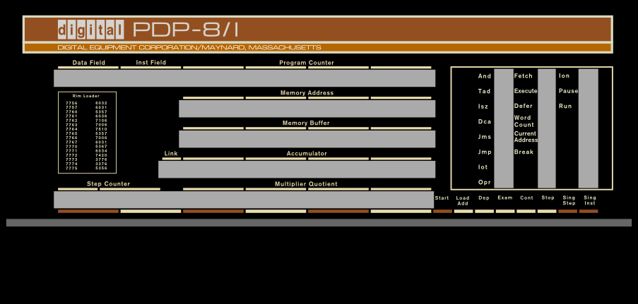
03/02/2015 at 18:46 • 0 commentsI finally finished the artwork for the acrylic panel and sent it off to a manufacturer in Germany. Final size is 30x14cm, a 2:3 scale replica of the 8/I. The reproduction is pretty much pixel perfect, with the exception of the bottom brown/white color bar being moved a few mm down from the original for a better cosmetic fit.
The panel has 65% translucent slots (marked in grey) where the indicator leds sit behind and will be done in 1200 dpi (not that anything beyond 600 dpi is noticeable but nice). Now I've got to wait 10 days for the test batch of 5 pieces to come home...
![]()
Note that the big black void at the bottom is where the switch panel is fitted. Looks weird without them.
Meanwhile, I spent time finishing off a separate PCB for the paper tape reader. It will be a 5x10cm 'sandwich' of two PCBs, with the paper tape pulled between the two layers. It could be mounted inside the PiDP-8 case, or in a separate box. Alas, the prototype I cobbled together on perfboard performs rather ho-hum so far. I guess I better hold off until I am sure this is the right way to go.
-
Adding a paper tape reader
02/28/2015 at 08:25 • 0 commentsNow the PiDP-8 basically works, I decided that it needs a paper tape reader for company. A friend gave me some PDP-8 tapes to test with, so yesterday was spent cobbling together a prototype.
Work was made easy because NeXT, at the Vintage Computer Forum blogs, shows how a grid of photodiodes on normal perfboard is enough to make the scanner part. So I copied that element, but decided to forego the other electronic bits and just use the analog pins from an Arduino Mini Pro to do everything straight from the photodiode outputs.
It seems to work, but it'll need a lot of testing to verify reliability. And a somewhat elegant PCB. Parts: Perf board, 9 IR leds and photodiodes, 18 resistors (for now) and an Arduino Mini Pro. Details on my project page as usual.
-
Booting OS8...
02/25/2015 at 23:35 • 0 commentsWorks! There are some finer details to finish in the switch handling, but all the front panel switches behave as they should except under some 'corner conditions' that need to be ironed out.
After finishing up today, I brought the two prototype PiDP-8s to our local hackspace/vintage computer meet and we booted up OS8. Jos, our very PDP man - if I may say so - kindly brought along some paper tapes with the BIN loader and FOCAL. As well as a small handheld paper tape reader I think I can clone into the PiDP.
Priority now shifts to getting the acrylic cover plate. The temporary paper one is getting on my nerves.
 This, of course, will spawn a whole new project: letting the PiDP code drive the real panel. But first, the PiDP replica needs to be finished. Risk of distraction :)
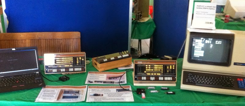
 It turned out exactly as I had hoped, so very happy. Well, almost exactly. It's the first of the four prototypes I ordered parts for, and I made a few mistakes handling the router. But who cares. Below is a picture of the PiDP-8 with its all-in-one peripheral: a USB hub of which one slot is the PTR (shown with two faux paper tapes, the BIN Loader and Focal69), two slots are disk drives, and the fourth is a removable disk cartridge.
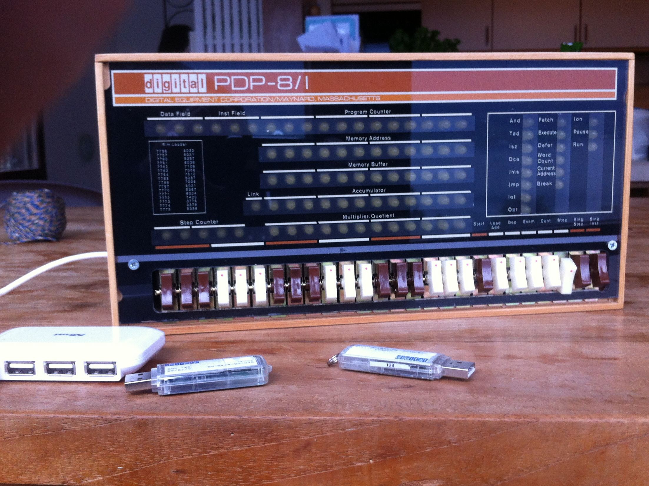
 More details on the