 Paul Kocyla
Here come some interesting new measurements, issues and some clues for the future.
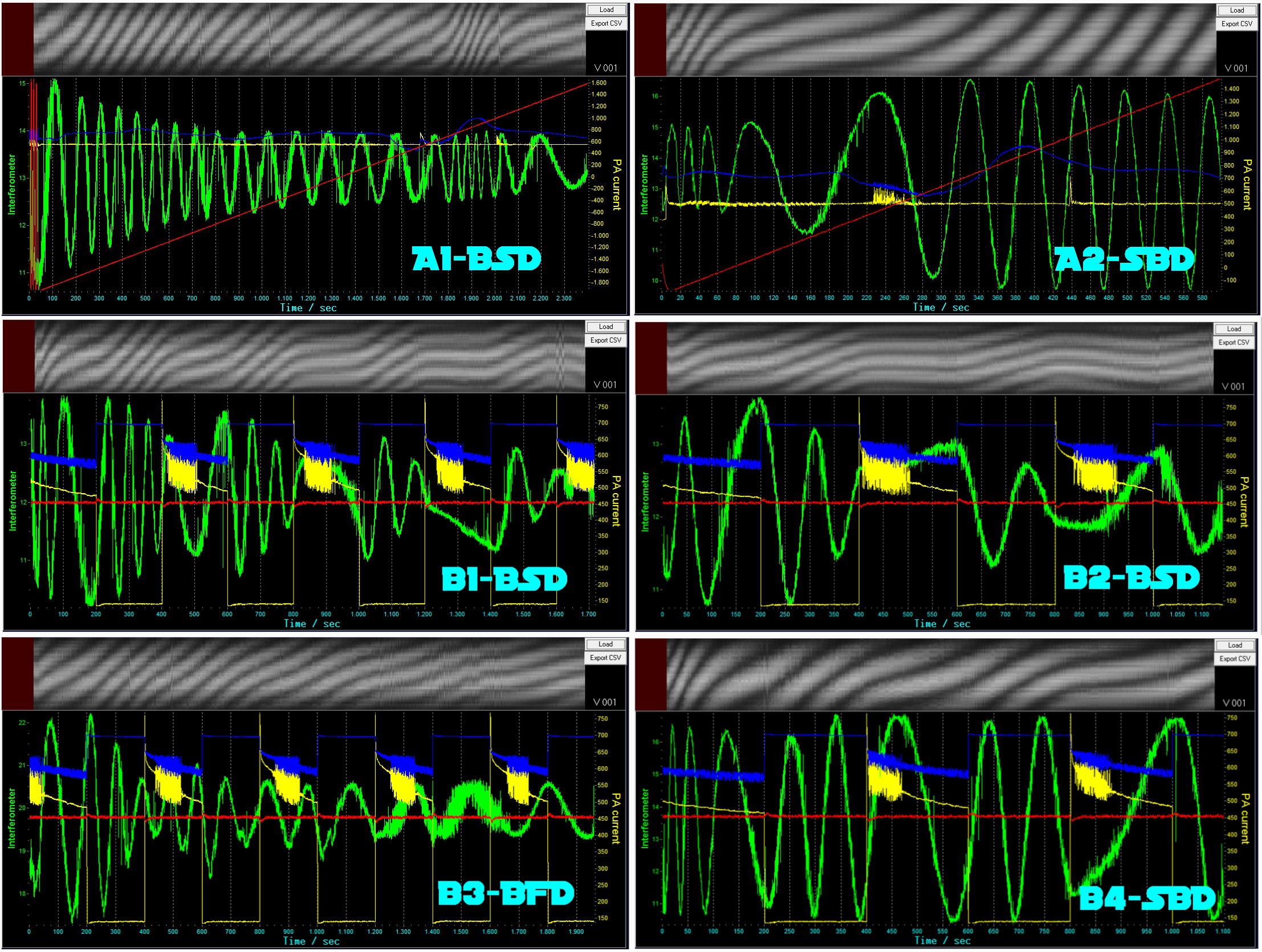
Let´s start with the charts B1-B4:
I set the frequency to 24.445 GHz. At this frequency, there was an interesting ripple in the PA current draw, so I focused on it.
I toggled the PA current ON and OFF and noticed quite strong forces.
The experiment was replicable many times, but the forces always push in the same direction, regardless of the orientation of the cavity.
I assume this is a thermal issue. When the RF source heats up, it produces a push.
Nevertheless this is interesting, because the forces seem much stronger in B1 and B2 than in B3 and B4.
B1 and B2 have the cavity orientation BS (see Explanation log), B3 is the cavity pointing to the ground, and B4 is SB orientation.
Maybe there is a superposition of temperature force and real force, but maybe the physical change of the cavity orientation causes the forces to appear smaller in the graphics. I think this is worth further investigation.
Now to the charts A1-A2:
This time, I kept the PA current constant (to avoid the thermal issue) and made a frequency sweep over long time.
In A1 you can see that there is a short band where a significant force occurs.
I took this band and applied another sweep with the cavity inverted - as seen in A2.
There occurs a force - and it is pointing into the opposite direction which implies that the EMdrive is working. However, I was not able to replicate the A1-A2 results even with 20 or more tests due to several reasons:
- There is a drift in the interference pattern over time. During long time eperiments, the pattern drifts into an unmeasurable state. It takes many tries (5-10) until the setup keeps the pattern stable for more than 20 minutes. It´s always drifting a bit, but usually after adjusting the mirrors, it will twist or blur our after a short while.
- The performance of the RF source depends on the temperature. So for a given current, it might degrade over time. Adjusting the current manually for long sweeps takes many tries. In most tries I could not see significant RX power changes due to wrong current ajustments.
Conclusions:
Both approaches are interesting for further tests.
Please let me know what you think about it.
The data is in the repository under "Charts\ProjectLog50"
Discussions
Become a Hackaday.io Member
Create an account to leave a comment. Already have an account? Log In.
Paul, did you ever played with a solar wind generator? These generators uses a needle as a bearing so it can move freely. Maybe its possible to detect moving forces faster if you able to put the cavity support on a form of hardened metal needle somehow. Water could have a form of brake force just as a magnet..
Are you sure? yes | no
Is it possible to transform the pattern into a audio wave? Analyse the pattern by ear..
Are you sure? yes | no
Interesting idea, I´ll try to implement it in the next software version
Are you sure? yes | no
Hi - could you put the cavity in a perfectly shaped cube-box? This way possible thermal-lift/drag will be the same, regardless of the orientation.
Please also make sure there is a significant distance between cavity to any metallic surface below. Maybe add wooden podium?
Are you sure? yes | no
The platform is light wood covered with duct tape. The interferecne pattern is stable now. According temperature: A thermometer measurement would be great - i am blind to that now. I will include it into the next generation RF source. Box shape is a good idea, I´ll try it.
Are you sure? yes | no
a quick and easy experiment is to try to put the whole unit on a slight angle (3 degrees) and run the same test again. if a different pattern emerge in the results, it could be the planar orientation of the RF source.
Are you sure? yes | no
Did. Works.
Are you sure? yes | no
did you try to use a Thermoelectric cooler (Peltier element) to cool the RF generator?
Are you sure? yes | no
No. But the heat from the peltier element´s hot side would also have to go somewhere. The RF source does not overheat, it´s well within its operating parameters.
Are you sure? yes | no
Find something metal that covers the -entire- 'resonance cavity platform'. Except for the mirror on the side, naturally.
Put a battery-powered fan -inside- the cover. Since it is all covered, the fan (or whatever you pick for cooling) won't be -thrust-. (Vibration, sure. But not -thrust-).
Strong circulation inside a sealed box -> pretty uniform temperature on the exterior of the -box-. Meaning that the forces on the box should end up pretty symmetrical, and thus ignorable.
Or just a much larger thermal sink for the RF? But -seal- it inside a cover - so the natural convection cooling going past the hot body shouldn't be any persistent thrust for the entire platform.
I have a square 'cake cover' that seems the right size. A punch bowl maybe? (Or, make something competent :D, just trying to think of something particularly quick to test.)
Are you sure? yes | no
Good idea, but a fan would cause too much vibration and blur out the interference pattern completely, so it must be sth passive. Aluminum foil maybe as a quick hack?
Are you sure? yes | no
Something to test at least. My hardware store has an 'extra heavy' aluminum foil. And there's roofing 'flash' if you're handy with tinsnips. I was thinking 'metal' for its heat properties, but thinking about it more I'm not sure I care that much as long as there's some physical barrier. It'll get hot inside, but I don't think your runs are long enough for that to be a problem, yes?
Are you sure? yes | no
Of course, this means you're making your experiment a tin-foil hat :D
Are you sure? yes | no
LOL yes. BTW I got a mail already writing that the government is trying to kill me... I need that tin-foil hat before they scan my location and drop chemtrails on me :-D
Are you sure? yes | no
And 'larger thermal sink' doesn't need to be 'more aluminum' necessarily. A little ice slush bath with as much of the heat sink as can be managed without electrical issues, perhaps. Ice slush has a long, long way to go energetically before steam starts providing thrust.
Are you sure? yes | no
I've seen some notes that an EMDrive will produce a torque around the central axis equal to the thrust produced. Um by rf source do you mean you think your issue is heat in the cavity or heat at the external rf source? If the later, maybe try getting a water cooling system intended for a chip and stick the radiator in a bucket of ice or something.
Are you sure? yes | no
It´s definitely the heat in the RF board, the cavity doesn´t get warm.
The problem is the heat dissipation of the RF generator and amplifier.
A vacuum test would be the solution, but I would need to rebuild the setup so it fits into my vacuum bell.
The RF source is also on the platform. Maybe it would help to sistribut the heat more diffuse, I´ll think about it.
The torque is interesting, it´s the first time I hear about it. This might really be the cause for this force, I´ll check it.
Are you sure? yes | no
If there is torque, you can try to place the Testrig on a support with a bearing so it can freely rotate. Any torque will be visible in rotating movement i guess (depend on the quality of the bearing of course)
Good job btw!
Are you sure? yes | no
I think you might be trying to do too many things at once. Pull the RF generator and isolate it from the system (for example put it in a cooler with some blue ice). Document a force acting on the frustum then start moving outward looking for an opposing force. Um, could you modify a fish tank to act as a vacuum chamber? Also, heads up, NASA managed to fry some of their electronics because they were not able to operate in a vacuum.
Are you sure? yes | no
btw, great work!!
Are you sure? yes | no
Thanks
Are you sure? yes | no
Really intersting.. Here, I think the most important step to take, is to stabilize test conditions. After that, you may want to retry many times the same test, in order for statistic expert to be able to explain - and detect - even small scale effects.
Here, it is not really clear how you determine that the force is due to the temperature fo the RF source. Have you measured that ?
I think you should continue with this kind of experiment (on off) and measure the force AND the temperatures, as I suppose that force should be in a way linked to the temperature (more deltaT_ambient -> more force). In this case, would just mean to characterise a source of noise (as I think may be easier then removing it...)
Are you sure? yes | no
I assumed that it´s a temperature effect because the force showed always in the same direction (although there was a visible difference when changing the cavity orientation). The heat dissipation was noticable even by touching the RF source casing. It might have been also a lorentz force or sth else, anyway it was parasitic, because it occured regardless of the cavity´s orientation.
Are you sure? yes | no
Is the force pointing away from the RF? This can be important, and be a result of the Lorentz force detected in the cavity. You should check this out..
Are you sure? yes | no
Can you test it turning also the RF source ? That may be useful to determine if it is linked to the rf orientation..
Are you sure? yes | no