 Paul Kocyla
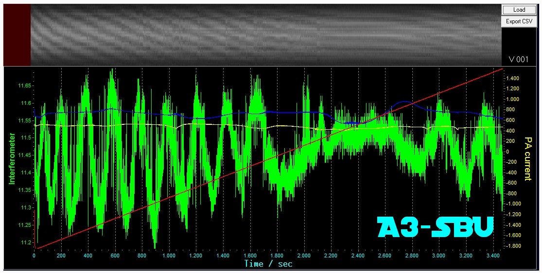
I could make the interferometer more stable by tilting the EMdrive platform down a bit on one side. The pattern is not jumpy any more and behaves smoother.
I could reproduce the A2 test from previous log and it shows force at similar frequency and the same direction as the previous test.
The BS (reversed) test showed nothing, but the RF source was already very hot and didn´t show good RF transfer, so I´ll repeat it today.
If it will be successful, I will modify the RF source so it can find the best conditions automatically.
If these tests can be reproduced several times, I will redesign the RF source.
I put the data into the repository (03-ProjectLog50 -> A3-SBU)
Discussions
Become a Hackaday.io Member
Create an account to leave a comment. Already have an account? Log In.
Hi Paul, awesome work! It's cool seeing all this data. Now you get to really explore what's going on. Also, sorry about not making the Hackaday Prize finals, but I hope you keep exploring this phenomenon anyways, for science :)
I have some thoughts on the interferometer. Fundamentally, what the interference pattern is measuring for you is the difference in time of flight for light to travel two similar paths. To make it measure what you want it to measure (displacement due to EmDrive force), it stands to reason that both paths should be as identical as possible. Except of course that one path is displaced due to the EmDrive, and the other is not. What you seem to be running into with the drift is that one of your paths is slowly lengthening, while the other isn't. I agree with you that it is probably something thermal. The platform itself could be heating up slightly, which changes its dimensions (most things expand when heated as you know), moving the mirror closer to the interferometer setup. It wouldn't surprise me at all if your laser was picking up that subtle shift.
Now this might involve a lot of work, so I don't know if it's worth your time right now (this is your project not mine, I'm just offering ideas!), but I wonder if you would get more stability by building up a second platform, identical to the first, minus the EmDrive setup, and mounting the secondary path's mirror on this platform. Put this platform right next to the other one, with the mirrors almost adjacent to one another, right on the edges of each. This will help eliminate any differences in path length due to warmer or cooler air on either side of your whole setup. The two lasers would be passing through (almost) the same air, just a centimeter or so apart.
Now if the main platform itself is heating up from the RF source and expanding this would still cause issues, but could be solved by building up a second RF source for the dummy platform. Power it the same as the primary, and they should heat up identically, or at least closer than what you are getting now.
Third, if you want to get really crazy, make a dummy EmDrive to take in the duplicate RF energy. Perhaps just a cylinder or something, ideally tuned to the same frequency as the real EmDrive under test. Correct me if I'm wrong, but everything I've read about the theory of EmDrives is that the conical shape is important to generating a thrust. If the cavity is a cylinder, no thrust should be produced.
Again, building up an entire second platform is a lot of work, but it would have two big advantages. First, in theory it should ease some of your noise and drift issues. The interference pattern may even be better behaved throughout the day since both platforms would be subject to the same building vibrations (if they weigh the same, break out your microscale!). More stability means you can perform more tests, and different types of tests, and the data should be cleaner. Second, scientifically this would go a long way towards isolating the phenomenon you are trying to understand. If you get a positive result it would help silence the doubters, though not to the degree that independent duplication would. With two nearly identical platforms (excepting the shape of the cavity), it becomes much harder to attribute the change in optical path length to anything other than a force from the EmDrive. Hope that helps, good luck!
Are you sure? yes | no
Thanx for the suggestion. Unfortunately I wouldn´t be able to make an exact dummy platform, because the whole rig is handmade and not reproducible at 100% accuracy.I am still fighting with several ambiguous results and playing around with different frequency sweeps, currents and just observing the curves - so it´s chasing ghosts with a system.I am repeating tests all the time and watching for some significant patterns which might lead to a clue what´s going on. I know it´s not real science, but when I´m stuck with no more valuable results, observing may eventually lead to something.If I find something plausible and reproducible, I´ll focus on that.
Are you sure? yes | no
there are industrial quality vibration buffers available for low prices (i use them regulary, they come in all forms and strenghts.
http://image.made-in-china.com/43f34j00sMjavfeLrKrS/Frist-Grade-Rubber-with-Steel-Buffer.jpg You can screw them under the legs of your table
Are you sure? yes | no