jeromekelty
-
Build Log 10- New neck joint and final assembly
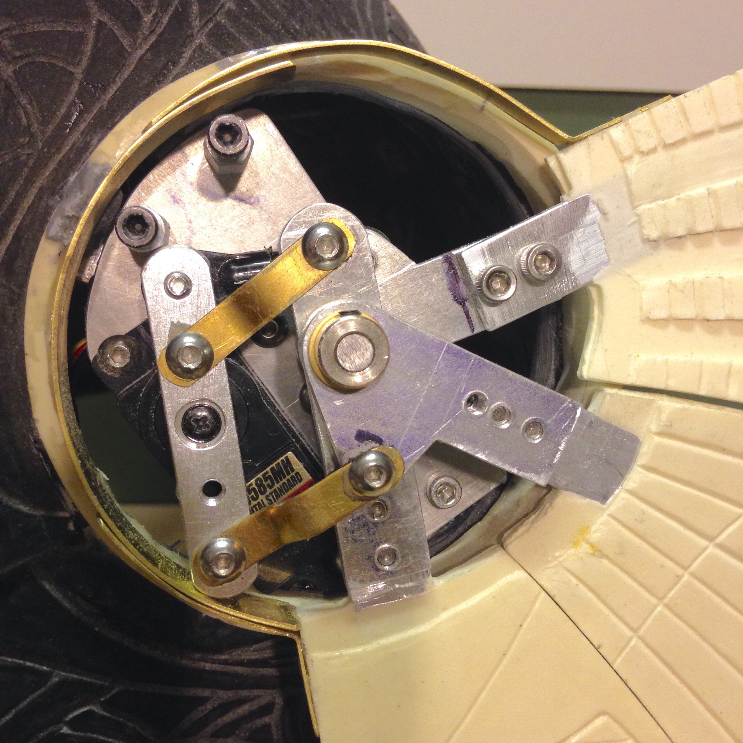
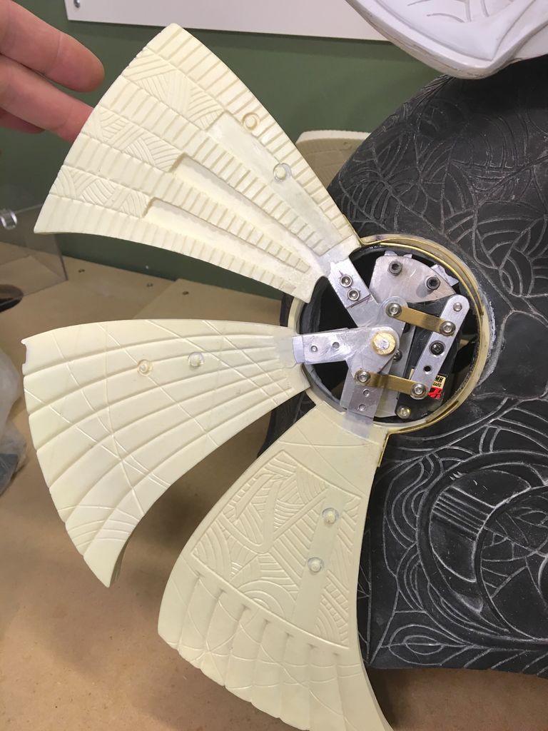
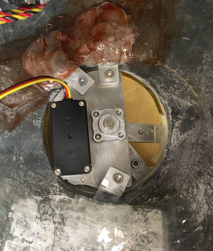
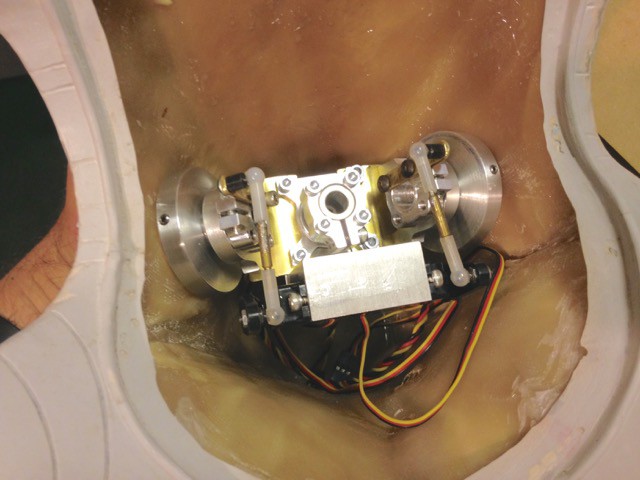
07/17/2016 at 23:16 • 0 commentsOnce I got the fan mechanics finished I had to install them in the helmet, which was really tricky because they needed to be perfectly aligned with each other and there is a separate angled piece that fits in between the fan blades and the side of the helmet that also has to be aligned correctly. I made Aluminum mounts for each of the fan mech base plates and secured them to the inside of the helmet with some ProPoxy20 (great stuff) and then applied a layer of fiberglass cloth with epoxy resin (I like West Systems) over it to reinforce it.
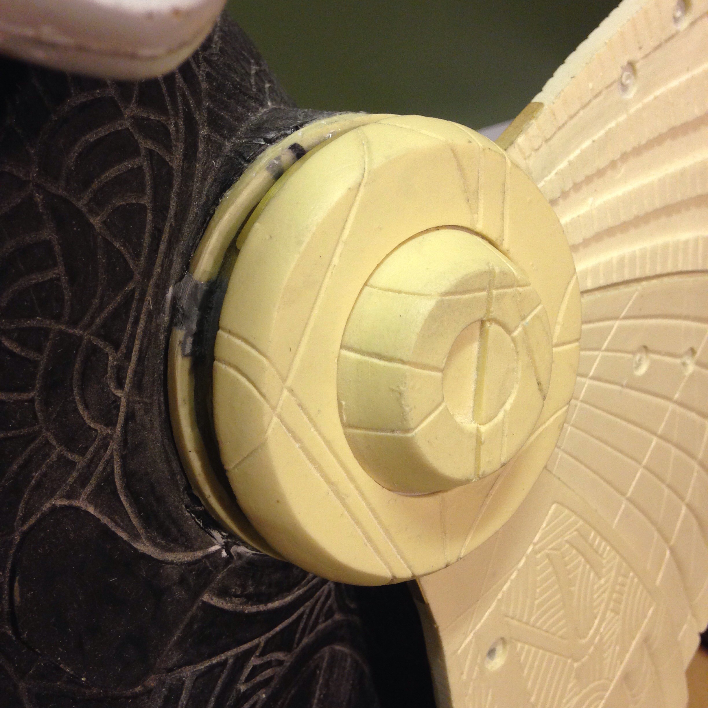
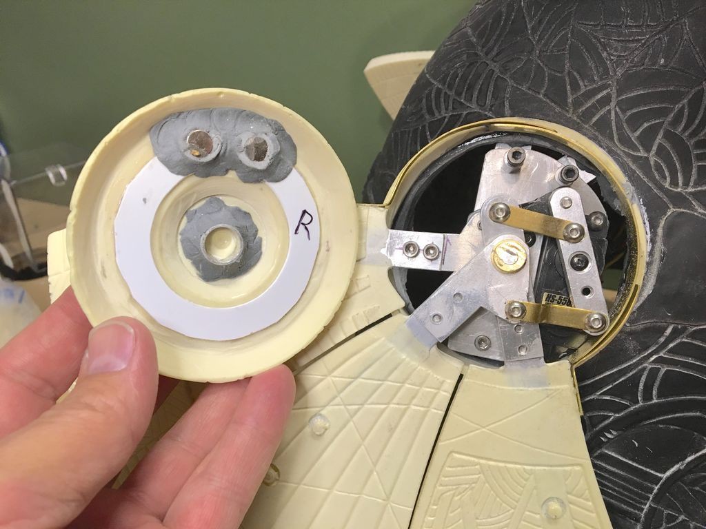
To fit the fan mech caps I had to hollow out the resin castings and then reassemble them with magnets and and a locating tube epoxied in. I also had to fit some brass trim that covers the gaps left as the fans rotate.
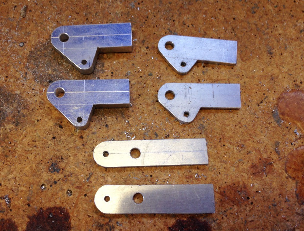
Once I got all of this done I realized the linkages that drive the fan blades were too large so I had to make new links from brass sheet in order for the caps to fit correctly.
![]()
![]()
![]()
![]()
![]()
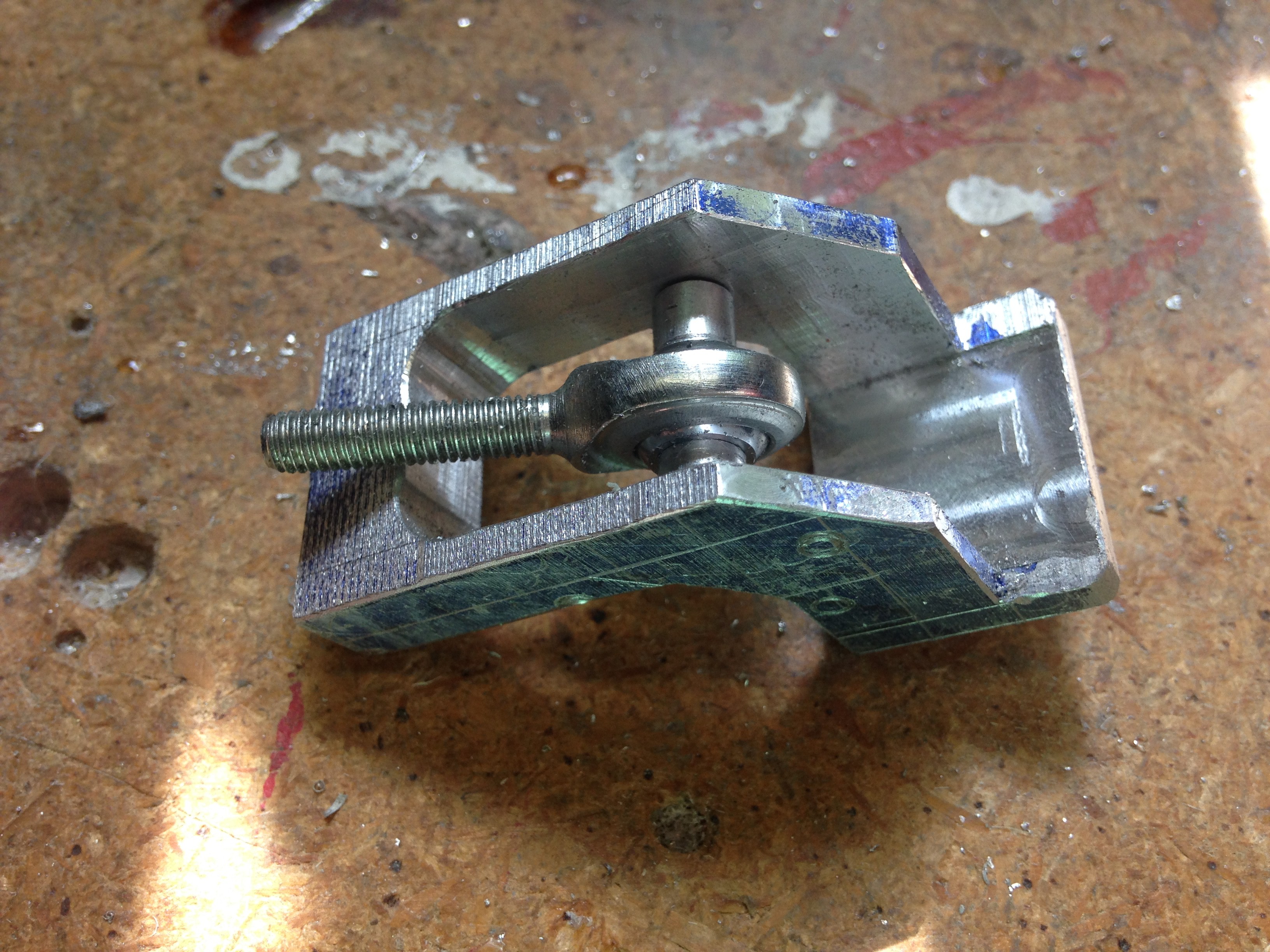
With that solved and the fans moving correctly I realized the head now sat too low and too far forward so I had to machine a new neck joint that raised the head up and moved it back a bit.
![]()
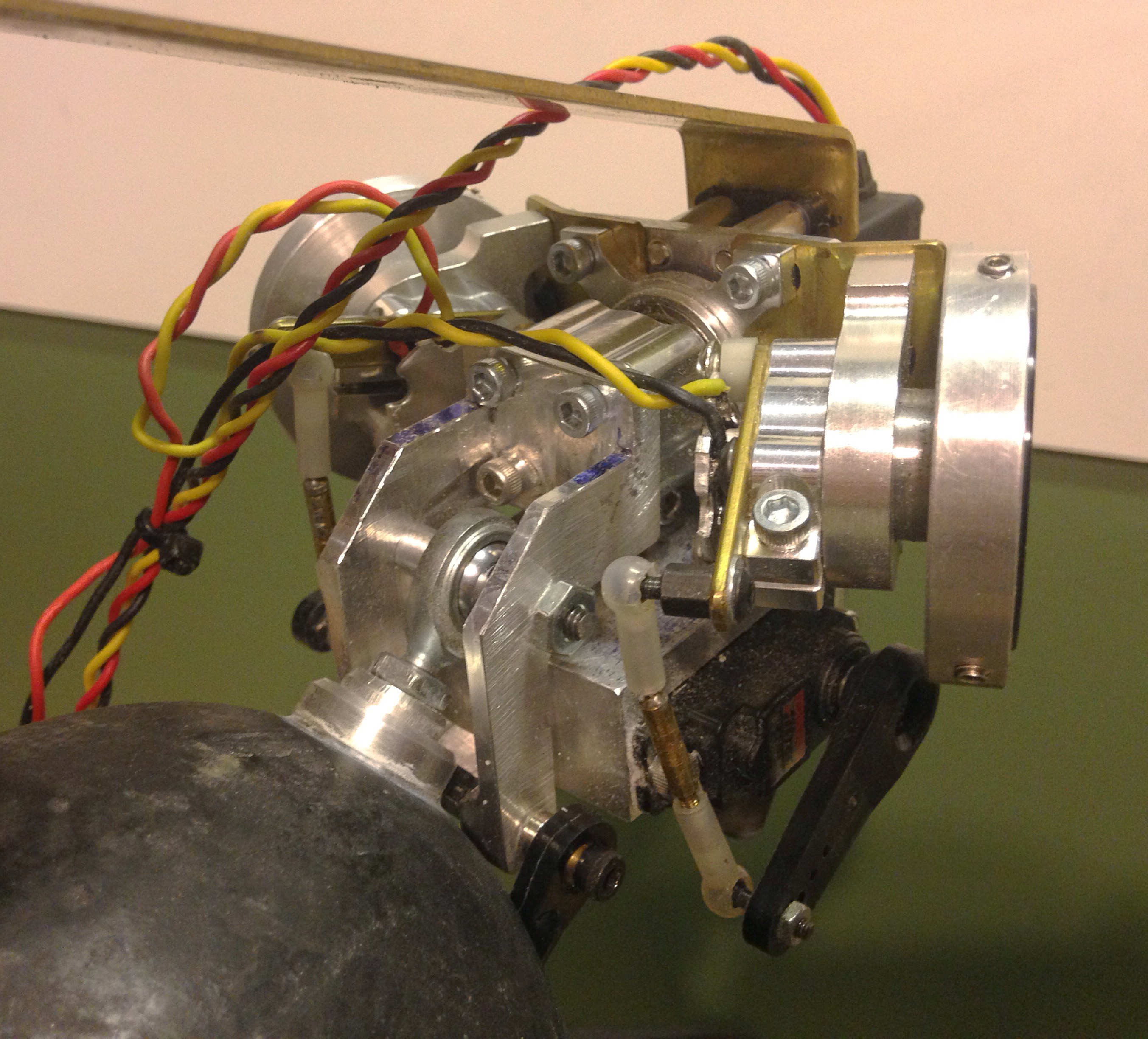
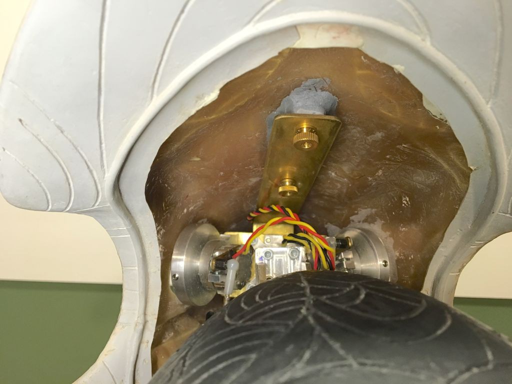
Here's the new neck joint installed-
![]()
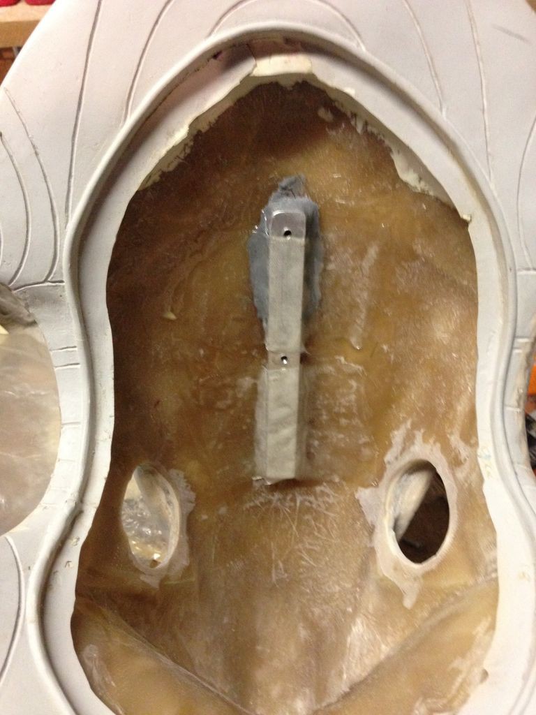
I drilled two holes in the brass sheet that mated up with two screws mounted to an Aluminum plate inside the head. The Aluminum plate was first attached inside the head with some ProPoxy20 and then reinforced with fiberglass cloth and epoxy resin. With this system the head could be removed by simply unscrewing two thumbscrews.
![]()
![]()
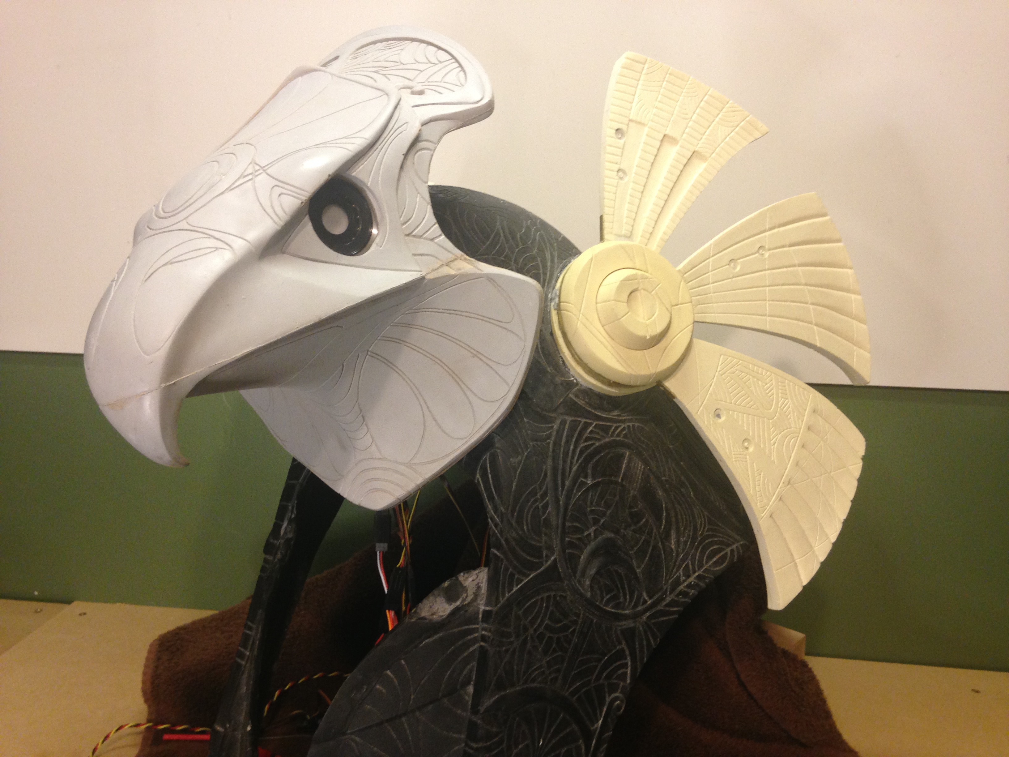
And with that the animatronic system is finished and good to go!
![]()
-
Build log 9 - Making the fans move
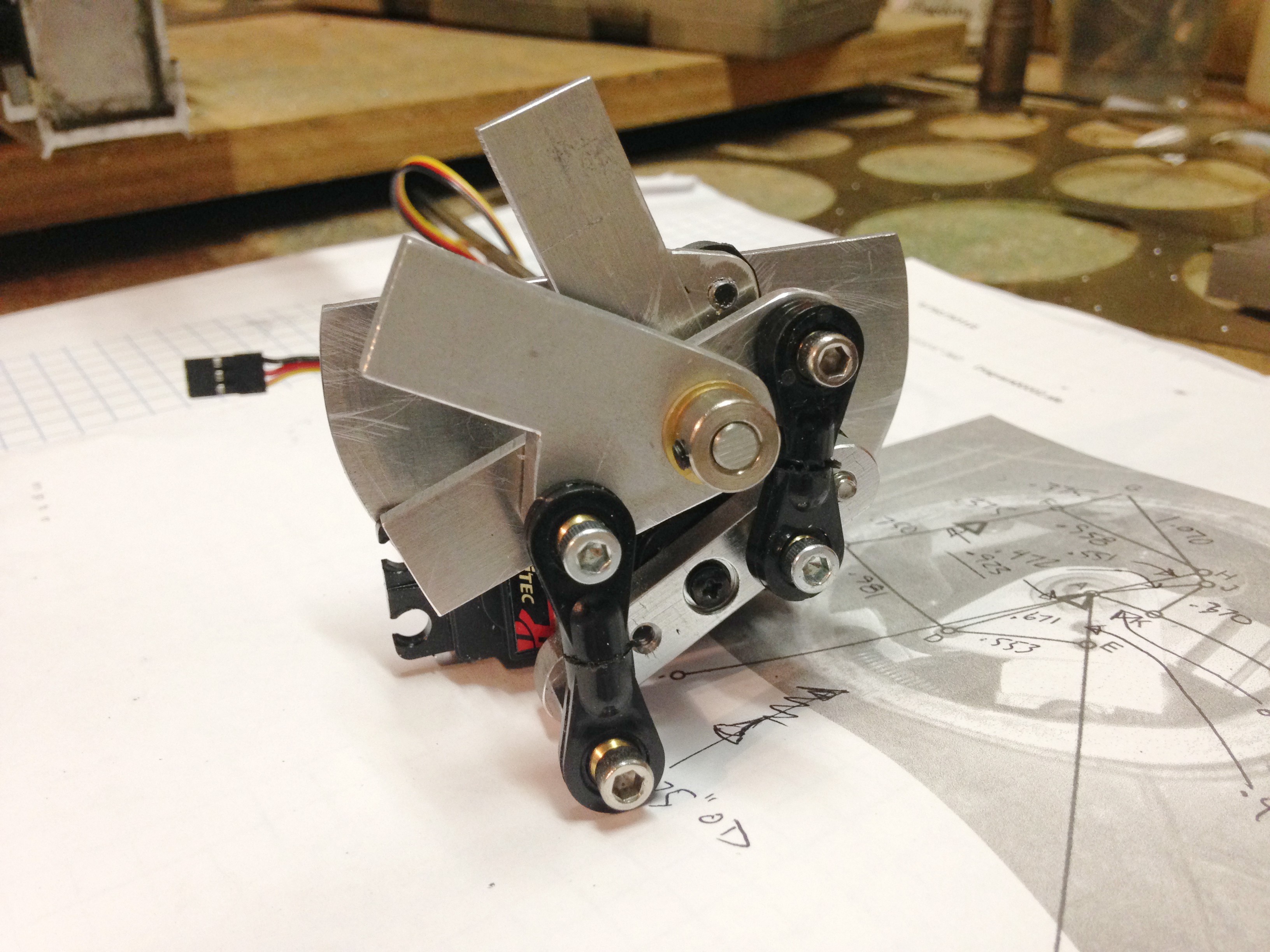
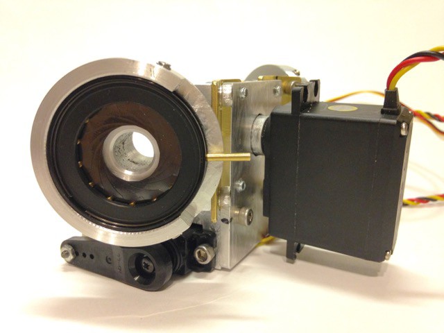
04/05/2016 at 05:34 • 0 commentsIn several scenes in the movie Stargate you can see how the fans on the sides of the Horus and Anubis helmets rotate in a progressive manner, with the upper fan moving the greatest amount and the lower fan moving the least. It's a really cool effect and the set of three fans on either side of the helmet was made to move using a single servo. It's a really compact mechanism.
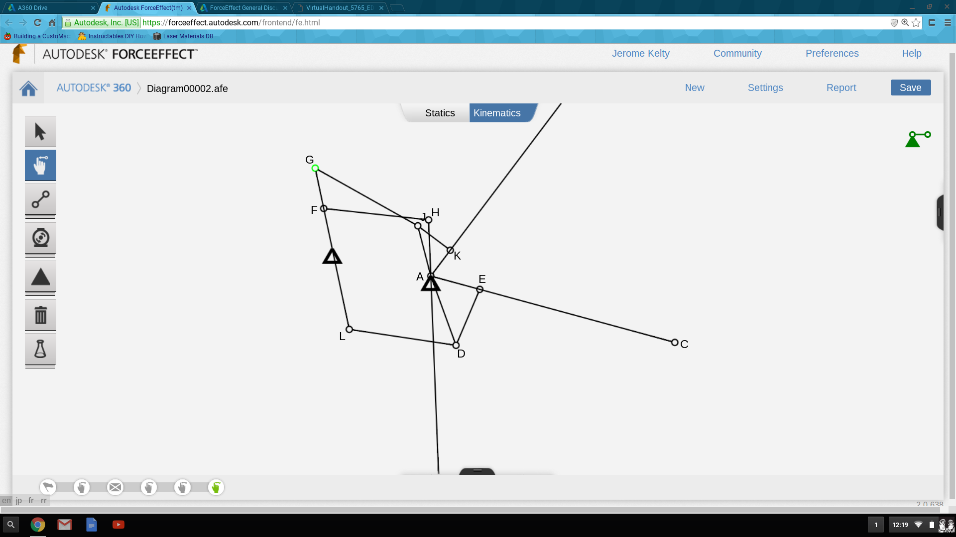
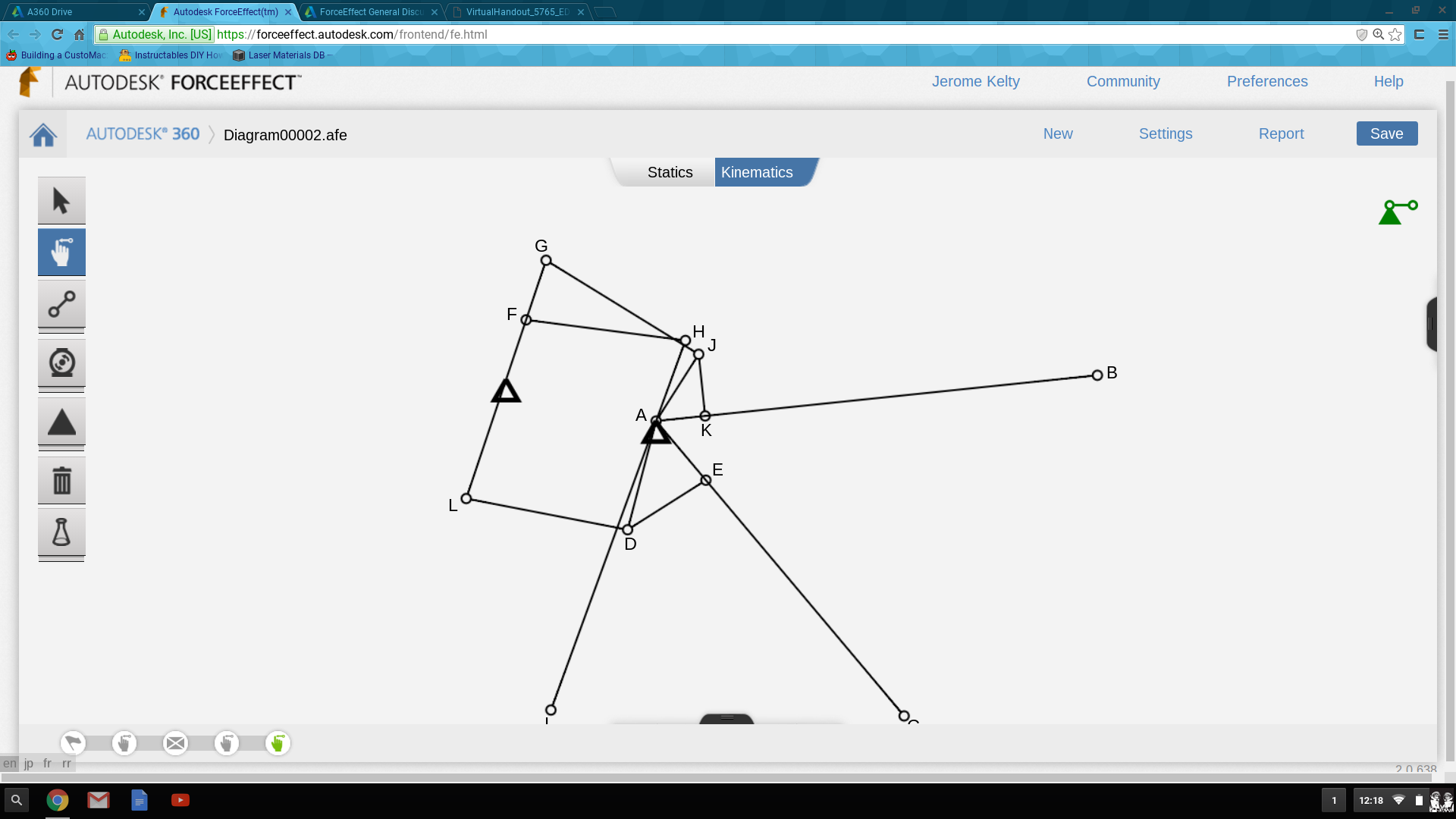
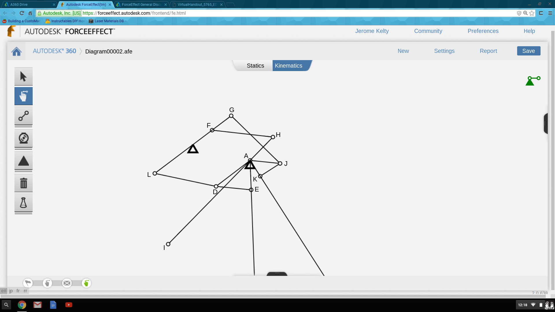
In order to replicate this I created a kinematic model of the mechanism using a free program from Autodesk called ForceEffect. This is an awesome bit of software that allows you to plot motions of all kinds of linkage mechanisms. I would have killed for software like this back in the day (20+ years ago) when designing suspension mountain bikes as I used to plot kinematics manually. The original helmet mechanics used helper springs to overcome the high leverage ratios- I have the benefit of modern digital servos that are much more powerful than the analog servos used when the film was made.![]()
![]()
![]()
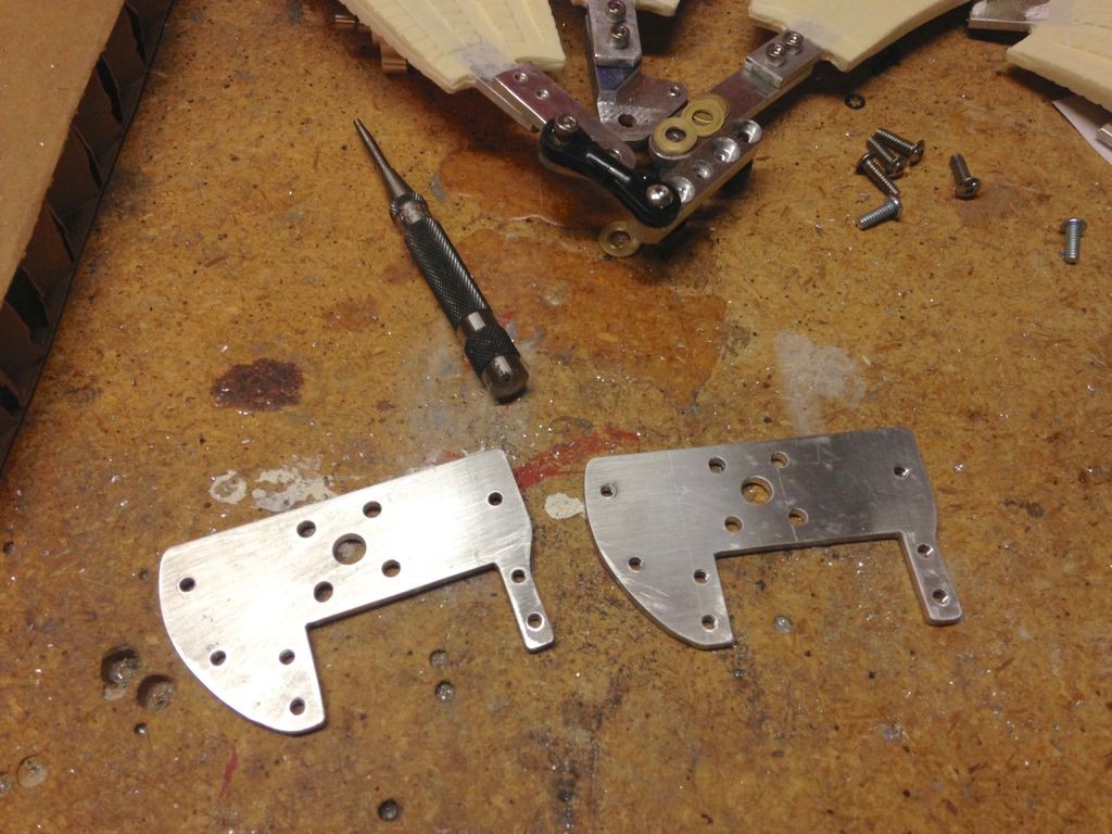
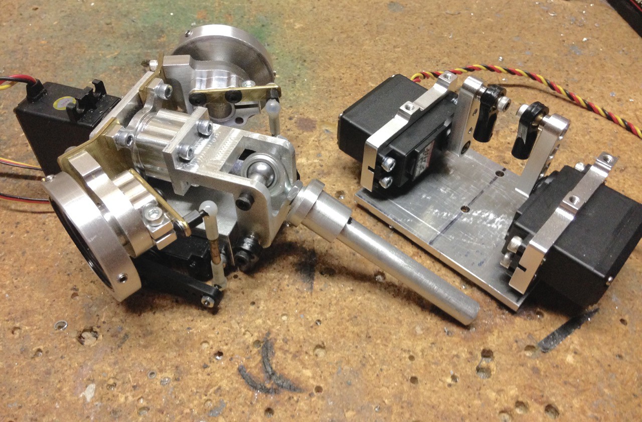
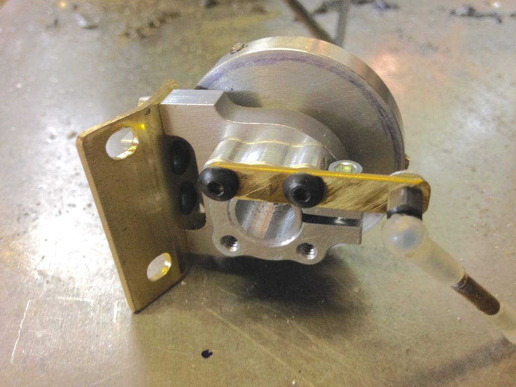
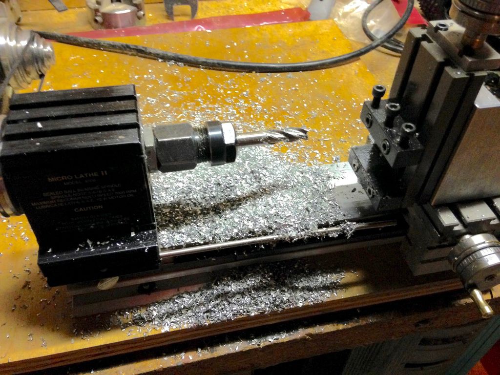
Once I figured out the necessary linkage lengths and pivot locations in ForceEffect I began building the fan mechanisms. First I cut the fan arms from Aluminum using a bandsaw, drilled the pivot holes and tapped the holes for the linkage screws using a 6-32 thread tap. Next I cut the servo mounting plates from 1/8" Aluminum sheet. The five holes in the center of the mounting plate are for the Actobotics 1/4" mounting hub that holds the fan pivot shaft.
![]()
![]()
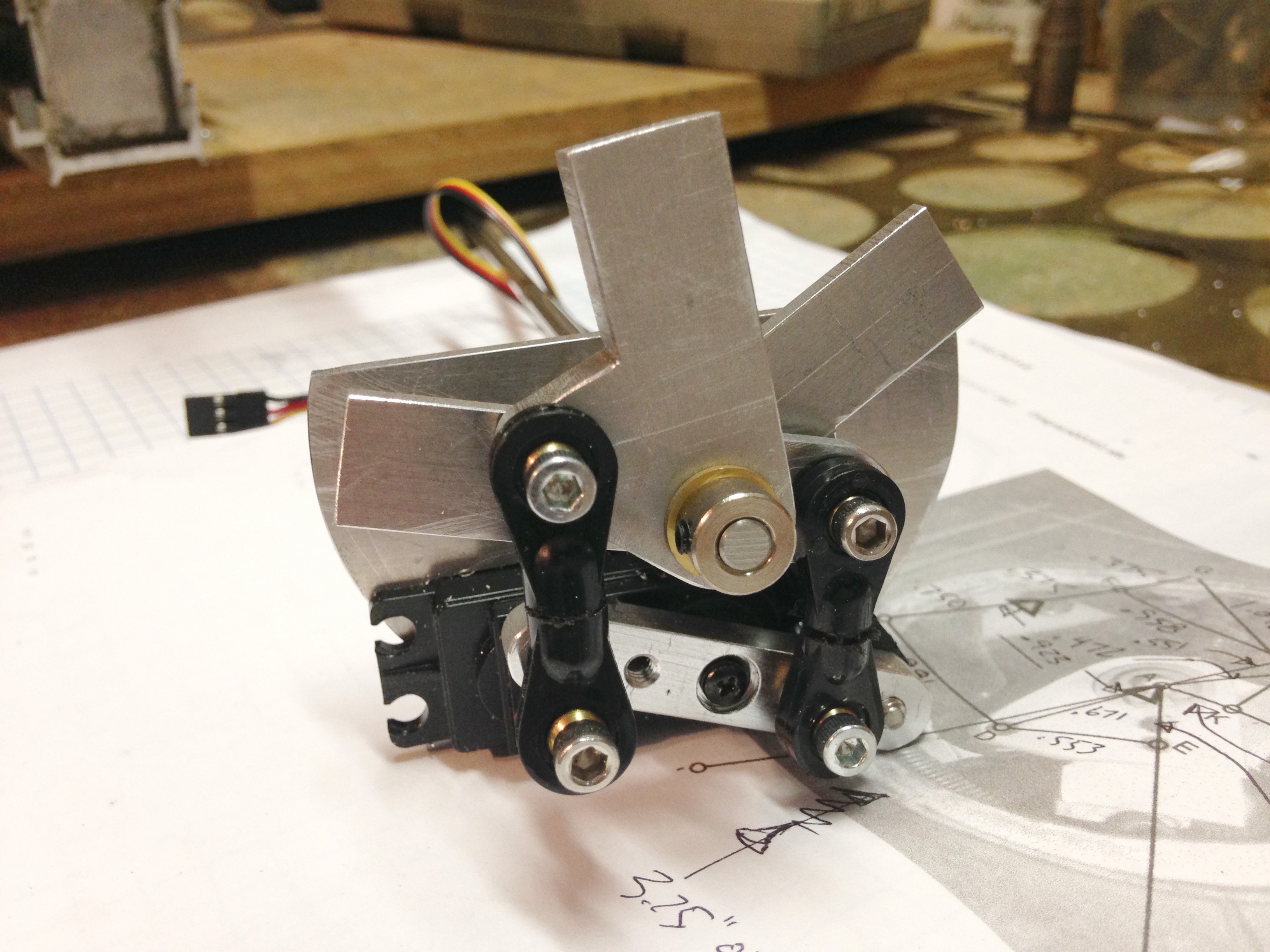
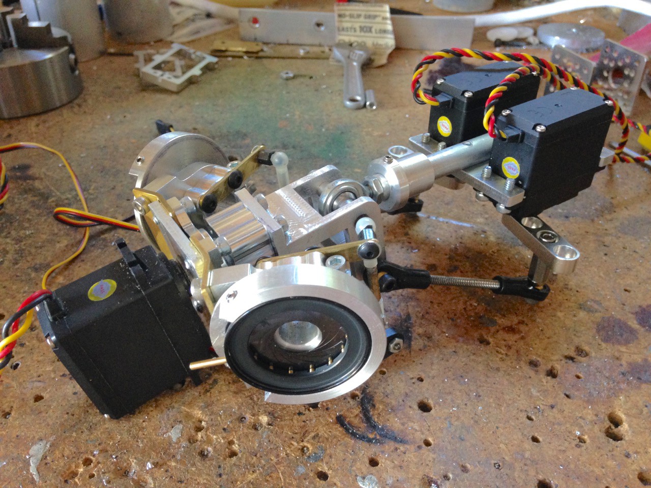
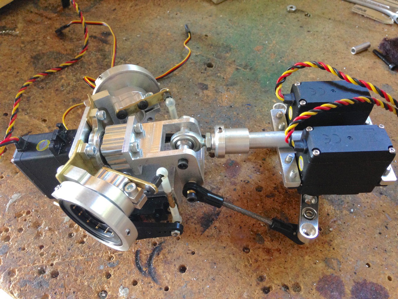
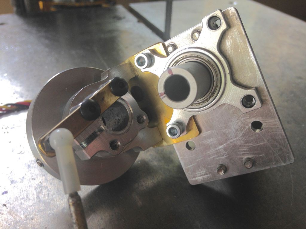
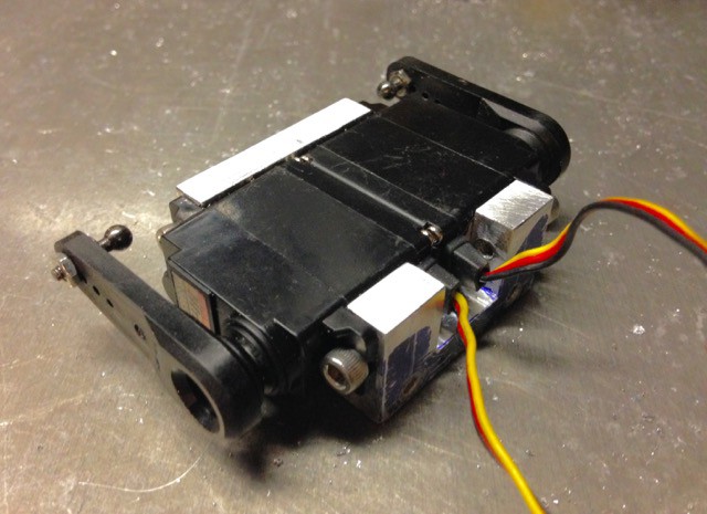
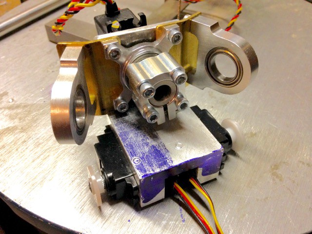
Here's the test fit of the assembled mechanism. Note that the schematic shows the left side of the head and this is for the right side of the head. In these photos I still have a little bit of relief machining to do and drilling of the fan blade mounting holes. The arms were slid over the shaft with brass bushings in between each arm and a locking collar holds the Aluminum arms on the shaft. Small linkages were made using 6-32 threaded rod and ball link ends.
![]()
![]()
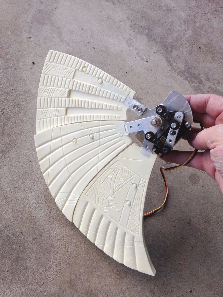
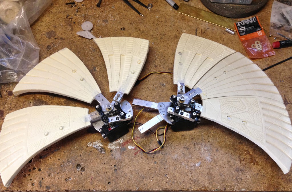
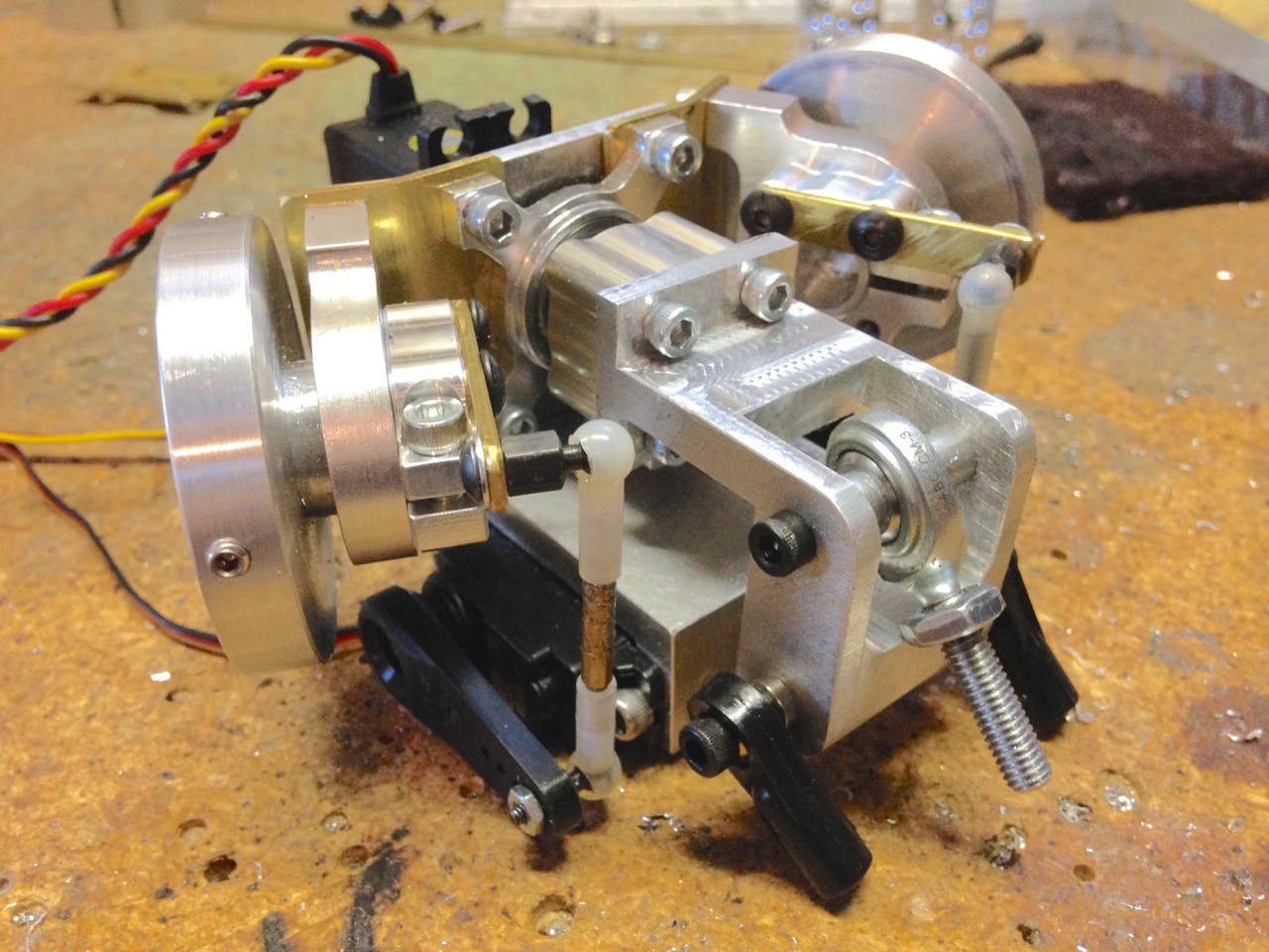
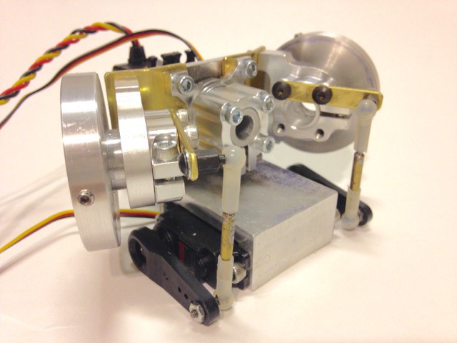
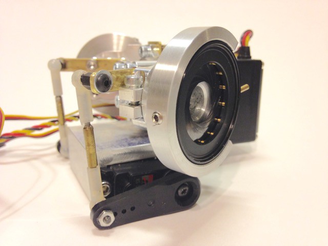
Once I was sure I liked the range of motion (and nothing was binding!) I mounted the fan blades to the individual arms with two bolts holding each fan blade. At this time I also made the mounting arms that bolted to the servo mounting plate.
![]()
![]()
And a quick test video of the finished mechanism with the fans attached- -
Build Log 8- Fail and save!
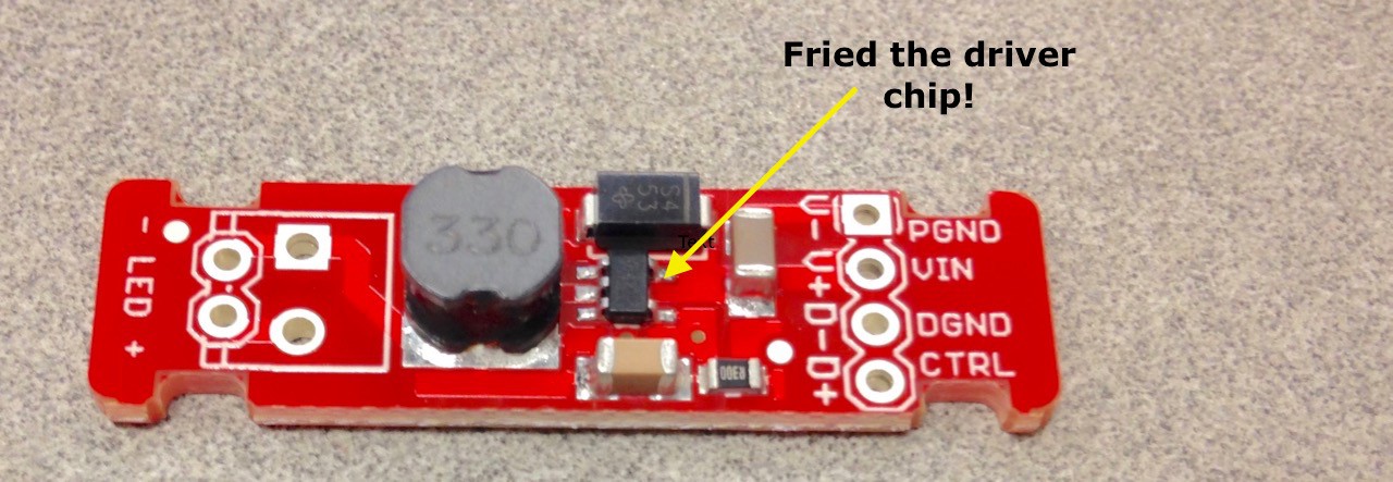
10/27/2015 at 03:24 • 0 commentsYep- I let out the magic smoke. While getting ready to do a test with the radio transmitter I accidentally reversed the power wires to the FemtoBuck and smoked the driver chip. I ordered a replacement AL8805W5 chip, removed the blown one using a hot air tool and soldered the new one in. Note to self- ALWAYS use polarized connectors!
![]()
As soon as I was back in business I set about making the RC radio receiver signal work with the FemtoBuck. The FemtoBuck is able to dim the LEDs by applying a voltage range of .5V to 2.5V to its control pin. The problem is that my RC receiver doesn't output a compatible signal so a fix is needed.
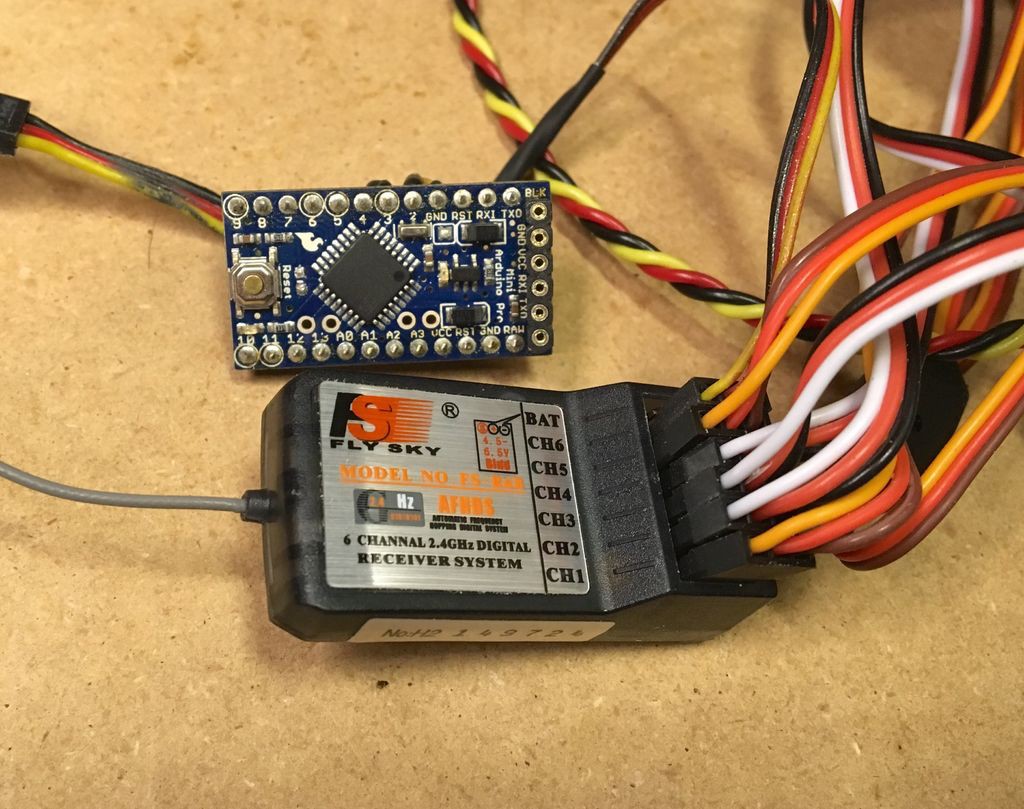
Arduino (Pro Mini) to the rescue! At the beginning of this project I thought I'd finally build something animatronic without an Arduino in it but the little bugger managed to work its way in there...
Using this code the Arduino was able to take the output of the receiver and turn it into something useful-
const int inputPinA = 2; // The pin connected to the RC receiver's servo output A
const int outputPinA = 3; // Output PWM pin Avoid setup() {
pinMode(inputPinA, INPUT);
}void loop() {
unsigned long pulseLength;pulseLength = constrain(pulseIn(inputPinA, HIGH), 1000, 3000);
analogWrite(outputPinA, map(pulseLength, 1000, 3000, 0, 255));}
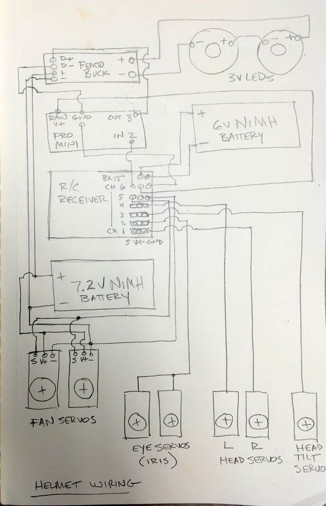
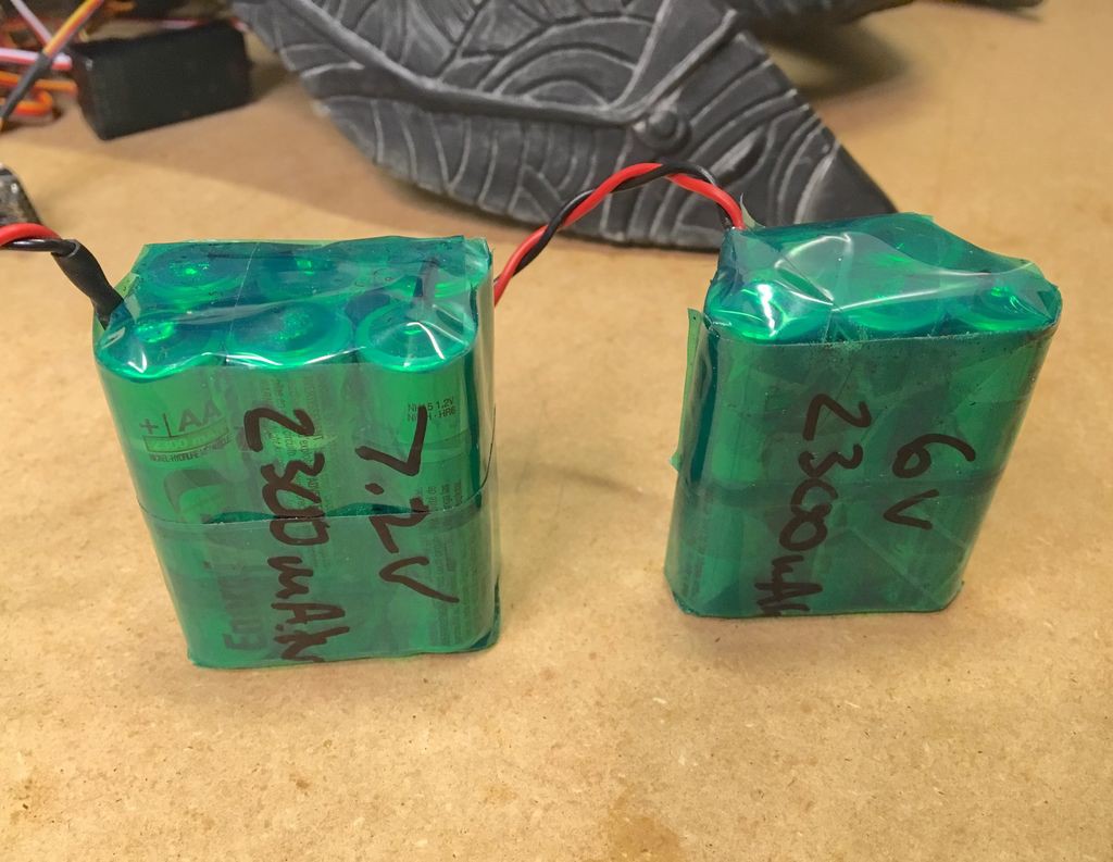
I also made two battery packs using AA NiMH cells- one 6V pack for the radio receiver, Arduino, head and eye servos and a 7.2V pack for the fan servos and eyes. The reason for this is the fan servos are rated for higher voltage and draw more current and the eye LEDs also want 7V + input power. In order to do this the fan servos are still connected to the radio receiver, but only using the signal and GND wires. The output from channel 6 on the receiver provides +6V, GND and the signal to input pin #2 on the Arduino. The output from the Arduino pin #3 provides the signal to the FemtoBuck to dim the eye LEDs. The wiring diagram shows all of the battery and servo connections and how power is routed in the system.
![]()
![]()
![]()
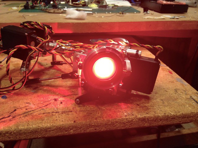
And with that I was able to get a full range dimmer for the eye LEDs using the RC transmitter. Here's the first test video-
-
Build Log 7- LED eyes
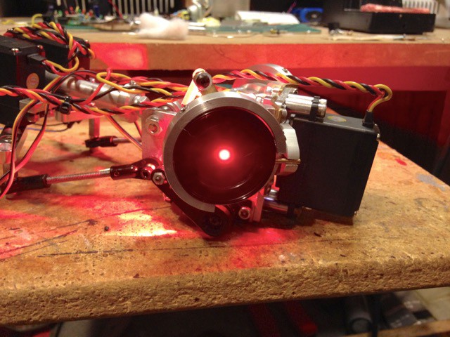
10/12/2015 at 18:19 • 0 commentsGot to work lighting up the eyes. The LEDs are rated at 3 Watts each (silly bright) and the driver board is a Sparkfun FemtoBuck. The FemtoBuck is a constant current LED driver board that can accept a PWM signal to dim the LEDs. Wired up the eyes and holy crap are they bright. They're perfect.
![]()
![]()
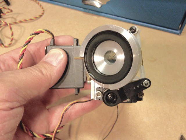
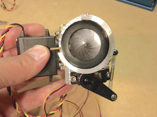
Next I made a clear sheet plastic lens, scuffed it with a scotchbrite pad and added some polyfill behind the lens to help diffuse the light and then I placed the lens behind the iris. So far I'm pretty happy with how it looks. The pics show the full range of iris motion.
![]()
![]()
![]()
-
Build Log 6 - Iris Retainers
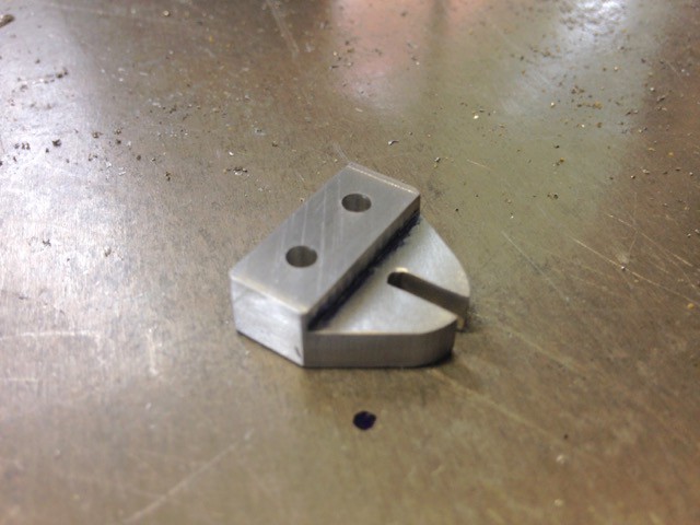
08/10/2015 at 04:58 • 0 commentsMade the retainers for the iris lever pins. These hold the lever pins in place so as the iris cup assembly is rotated the iris opens and closes. I machined the retainers from Aluminum plate and they are held onto the iris bearing assembly brass plates with 6-32 screws.
![]()
![]()
![]()
-
Build Log 5 - Head Movement Servos
08/10/2015 at 04:45 • 0 commentsMore work done. The 10-32 rod end is threaded into a 3/8" rod and the rod has a collar with a set screw that holds it in place. The collar is positioned at the top of the main helmet body and moving the rod in the collar allows you to adjust the distance between the body and head castings to get the spacing just right.
The servos that make the head move are mounted to an Aluminum plate using Actobotics servo mounts. The 6-32 ball links are threaded onto Actobotics Aluminum servo arms which are fitted to Hitec HS-645MG servos.
![]()
As it turned out the servo mounting plate assembly I made was a tiny bit too wide. I could use the current setup if I changed the servo arms and used smaller end links as it would allow me to position the servos closer together but the smaller 4-40 nylon end links have a tendency to break under higher loads. I hate it when things break so a quick re design was necessary.
Here's the new servo mount assembly. I had to flip the servos 90 degrees in order to make it fit properly in the main helmet section- now it’s good to go. There is a milled flat area where the servo plate bolts to the 3/8" round rod and the plate is held in place with two 6-32 screws. I still need to trim the servo arms but I’ll wait until it’s time for the final assembly.
![]()
![]()
-
Build Log 4 - Head Swivel Joint
08/09/2015 at 23:36 • 0 commentsI machined the head swivel joint mount from Aluminum. This attaches to the forward servo 1/2" servo extension clamp with four 6-32 screws. The swivel joint is a 10-32 rod end and it's attached to the mount with a long 6-32 bolt with machined spacers. The swivel joint allows the head to move up/down and left/right. The 6-32 ball links on the bottom of the mount will attach to the servos that make the assembly move.
![]()
-
Build Log 3 - Eye Iris Cups
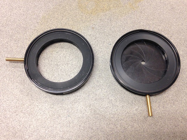
08/09/2015 at 23:29 • 0 commentsHere's the eye iris I'm using. They measure 37mm OD x 5mm thick- perfect size! The iris apertures are available from China via eBay but you can find them in the U.S, from companies like OptoSigma and Thorlabs. The trick is finding one with the correct dimensions and we just lucked out with an eBay find as they were a lot less expensive than sourcing stateside.
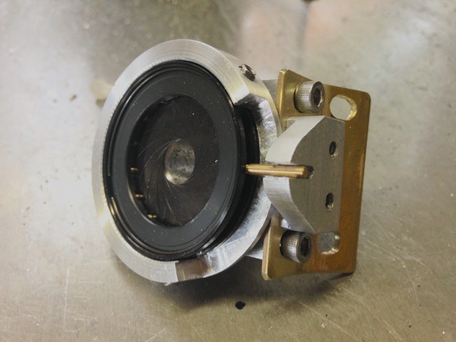
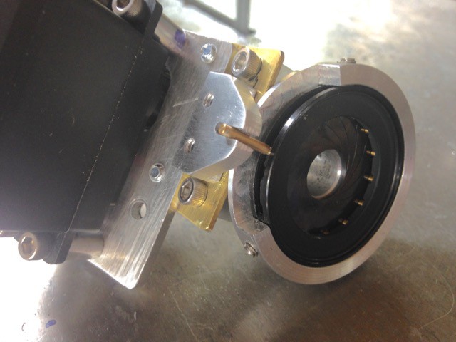
Full open to full close requires rotating the pin lever 90 degrees. Because they are identical, in order to operate them properly the right and left servos need to rotate in opposite directions. The way I've designed it the pin lever is fixed and the iris body rotates- it's housed in a machined cup that rotates in the bearing mount.
![]()
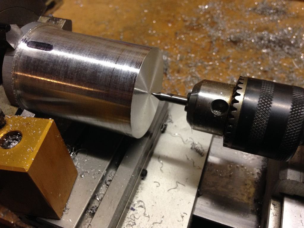
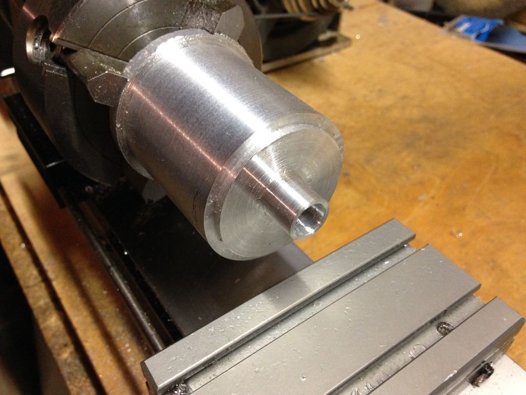
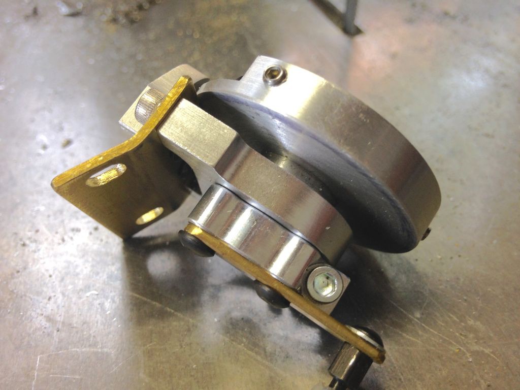
I machined the eye cups from solid Aluminum round bar stock. Each iris is held in place with three 6-32 set screws. The cup has a shoulder that sits against the 1/2" bearing mount and it's held in the bearing with a 1/2" Actobotics clamp. A small brass arm is attached to each clamp and a short ball link rod allows the servo to rotate the iris cup.
![]()
![]()
![]()
![]()
![]()
![]()
![]()
![]()
It's a perfect fit in the head casting… no room to spare!
![]()
These two pics show the range of iris movement from full open to full closed.
![]()
![]()
-
Build Log 2 - Iris Servo Mount
08/09/2015 at 23:13 • 0 commentsI made the mount for the eye iris servos. I machined this from a block of Aluminum using a milling attachment on my benchtop Taig lathe. It's attached to the forward servo plate using two 6-32 screws. The servos are a pair of Hitec HS-5085MG digital servos. Since the servos are required to turn in opposite directions using digital servos allows me to simply program the servo rotation direction without having to modify the servo. IN order to get the proper movement from the servos I installed longer heavy duty servo arms.
![]()
![]()
![]()
-
Build Log 1 - Forward Mounting Plate
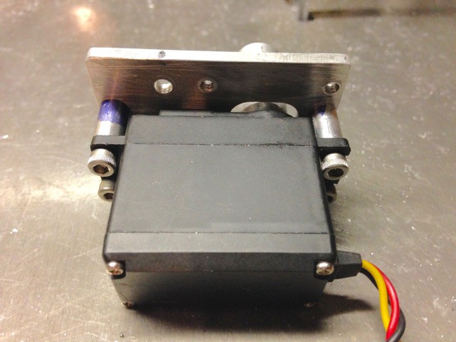
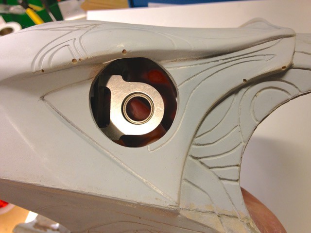
08/09/2015 at 23:00 • 0 commentsHere's a pic of the forward head mounting plate. The servo behind the plate allows the head to roll from side to side. The two bearing mounts are for the working eye iris. I still need to add the two iris servos, iris cups and the rod end mount to this piece.This is a lot more complex than the previous version I made. Even though this screen accurate head is much larger than my previous low budget version there really isn't much room in it and getting everything to fit properly has been pretty tricky.
I generally try to use as many off the shelf parts as possible as it makes the build easier and makes repairs simpler/faster since I don't need to re machine pieces if something is damaged. In this regard I use a lot of Actobotics parts from Servocity, in this case the iris bearing mounts, 1/2" servo shaft extension, 1/2" bearing support and 1/2" shaft clamp. The servo is a Hitec HS-645MG.
![]()
![]()
![]()
![]()
Animatronic Stargate Helmet
A replica screen accurate animatronic Stargate Horus helmet.