 The Big One
I finally found the time to perform the board and frame modifications I had planned. There were a few changes which were outstanding:
- Add all three 2200uF capacitors to try to smooth the power supply fluctuations a bit (powering 18 servos from 4x AA batteries results in massive voltage drops when all 18 servos are moving; see the video below for a visualization of this)
- Flip the radio connector to the top of the board, so that you can swap radio modules without taking the entire control board off the frame
- Re-cut the servo layer to include the new brace holes (to prevent the servo layer from wiggling back and forth when the coxa joints move)
First off, we have the filtering capacitors. I took before and after measurements on my shiny 'new' $40 oscilloscope to see what has changed. For the first test, I had no capacitors on the battery line, and I had a single 470uF capacitor on the 3.3v line. This is sufficient for reliable operation (if you don't have the capacitor on 3.3v, the AVR will brown out and reset as soon as the robot starts to move).
These videos show the unfiltered battery line and the 470uF capacitor on 3.3v. In these and the next two videos, I have the scope set to DC coupling mode, with 1 line on the screen equating to 2 volts:
As you can see, on the battery supply we drop from a nominal 4.8 - 5v to as low as about 2v at the lowest point. Likewise, the 3.3v supply will drop to about 2.2v at its lowest (thanks to the 470uF cap).
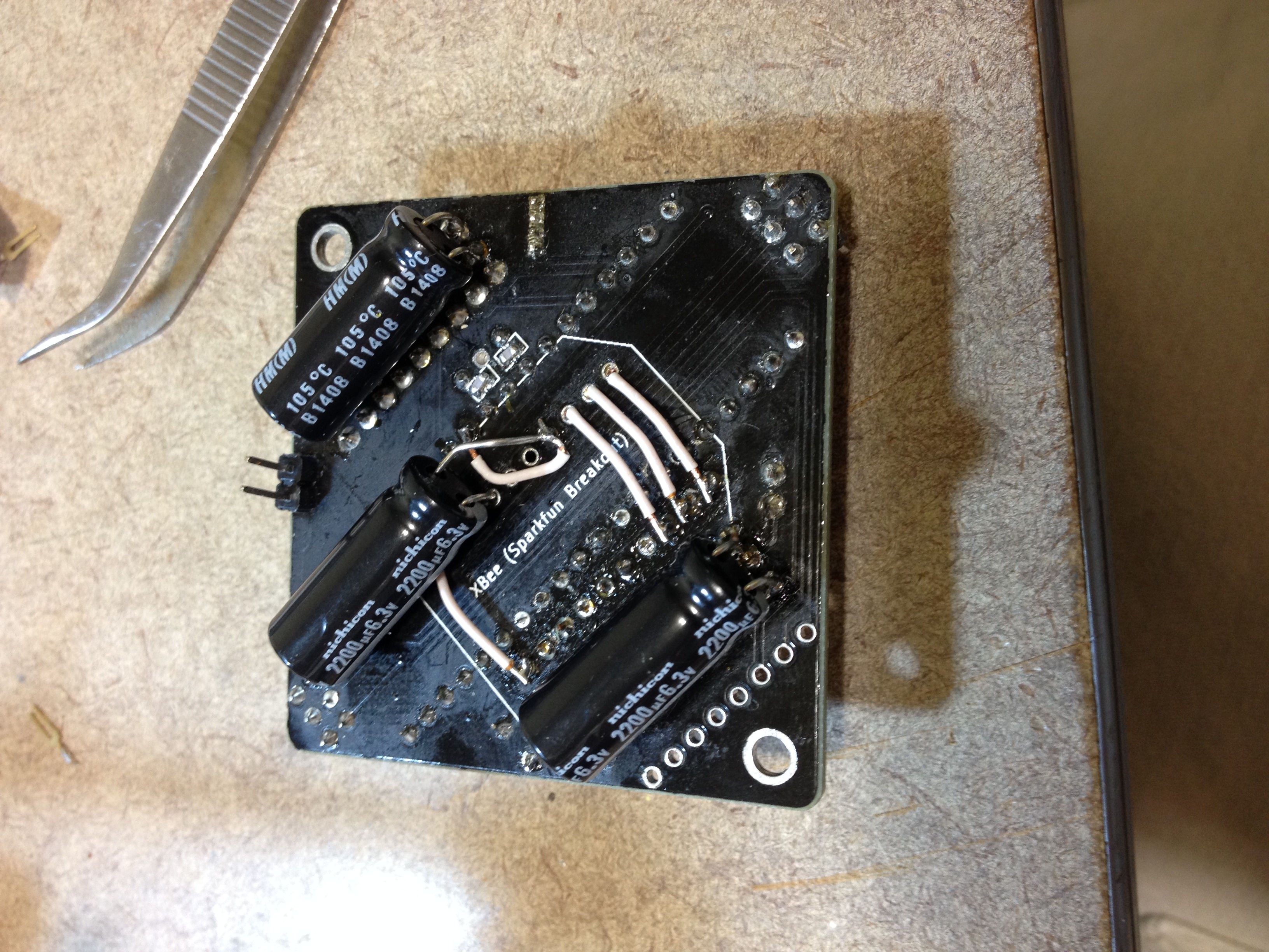
I then proceeded to add the capacitors. I put one 2200uF cap on each side's servo power supply rail, and one on 3.3v:

(I had already removed the female headers for the radio from the bottom layer)
After I had everything back together again, I re-tested. The results are not perfect, but are much better:
The battery line now does not seem to drop below about 3v, and there is no visible ripple in the 3.3v line. (Eventually I will take a look at things in AC coupled mode with a higher resolution, but for now this is sufficient to show what a very real difference can be made with 3 big capacitors.)
Next, the radio has been moved to the top of the board to allow easy access and swapping. To do this, I desoldered the female headers from the bottom of the board. I then re-soldered one of them on the top (on the row beside the AVR). I soldered some jumper wire between the old and the new headers. The picture of this happens to be the same one as the picture showing off the capacitors, so here it is again (the first three pins are 3.3v, RX, and TX; pin 10 is GND):
The top side of the board looks a lot cleaner. You can see the headers beside the AVR:

Finally we have some shots of the control board sporting interchangeable radio modules:

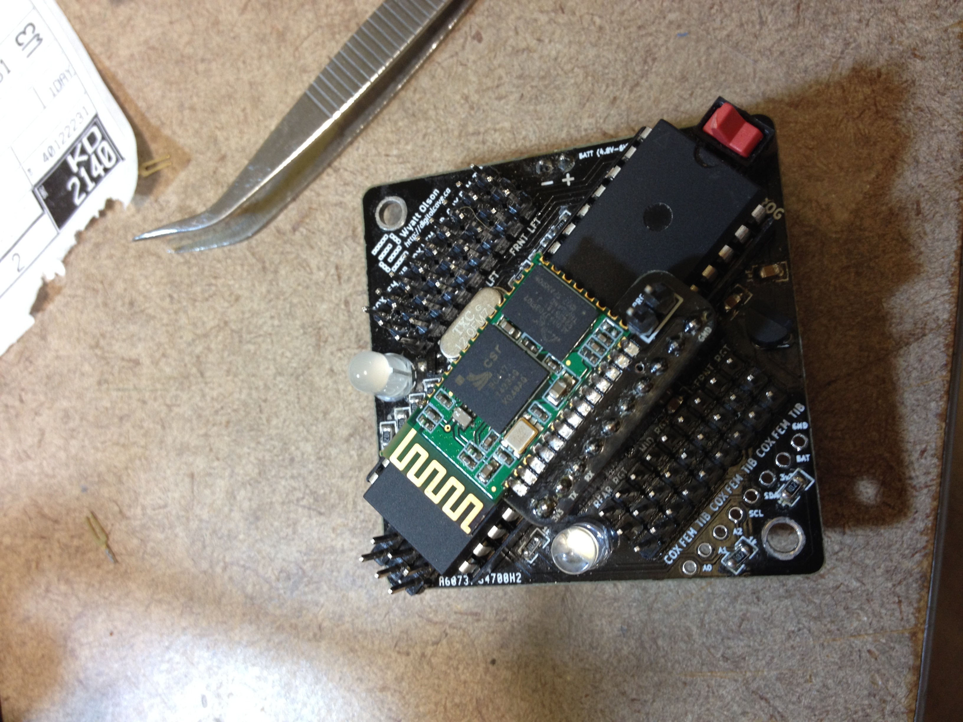
Both of these radio modules are attached via custom breakout boards I designed. I am not sure, but I don't think the Sparkfun board would fit here - sorry! :-( I am planning a rev2 board which will have the breakouts included as panelized additions... if I ever finish that, it will be a bit easier to support interchangeable radios.
Finally, the frame needed some work to bring it up to the latest plans. I designed this change a while back, but didn't implement it as it would have entailed taking apart the entire robot, and I wanted to do that along with all other changes (unscrewing lock nuts which have been placed far down a threaded rod takes a long time...)
The finished, re-assembled version is here:
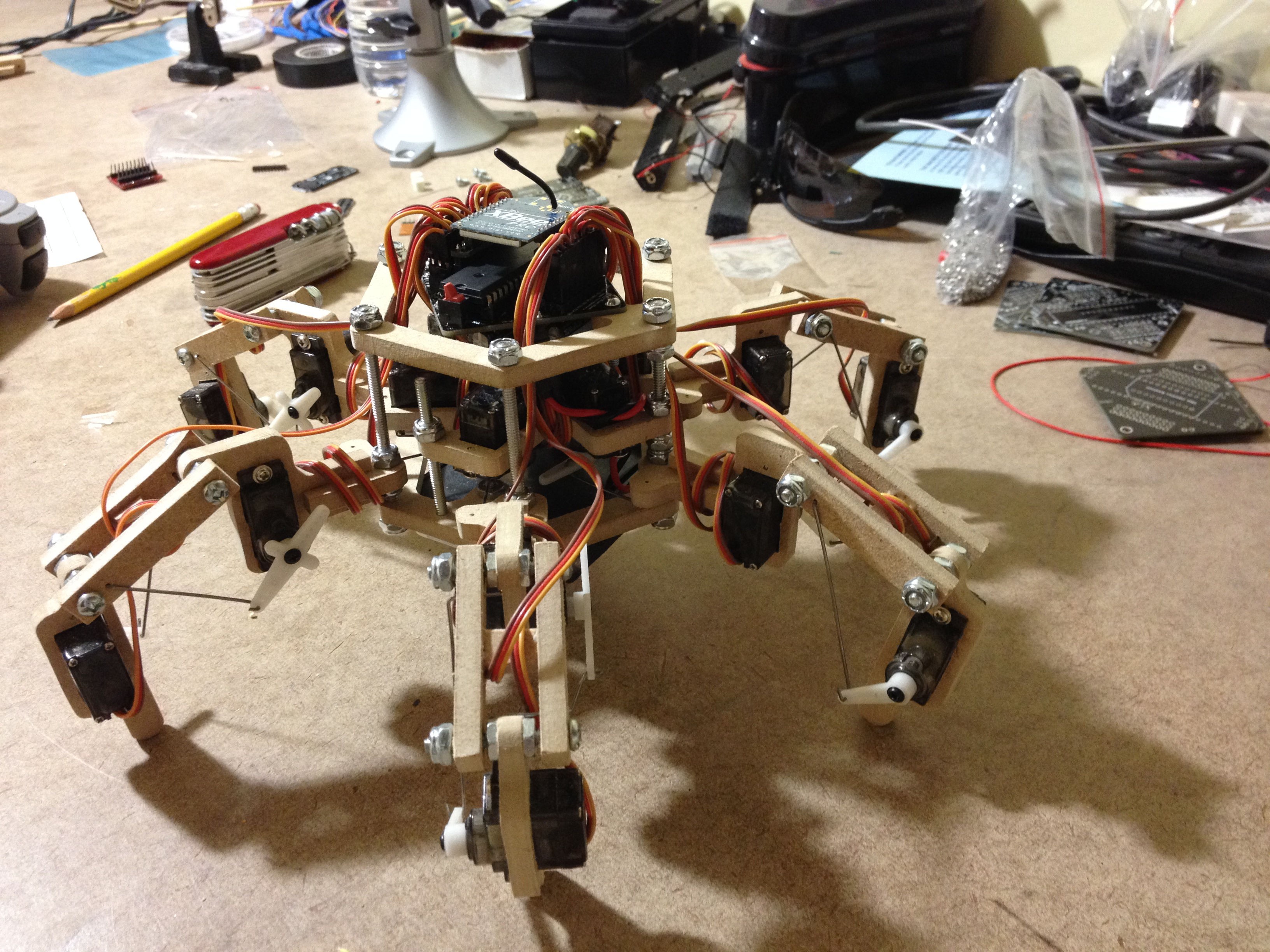
(In particular, node the 2" screws going up from the bottom and through the servo layer. I probably should have used threaded rod and gone through all three layers like I tell other people to do in the plans, but that would have required taking even more stuff apart, and it was getting late already).
Now that I can swap radio modules on the fly, the next step is to verify that the bluetooth module works. I hope to have time for that one tomorrow...
Cheers
Discussions
Become a Hackaday.io Member
Create an account to leave a comment. Already have an account? Log In.