Close
0%
0%

Animatronic Iron Man MKIII suit

RFID tags in the gloves control shoulder rockets pods, hip pods, forearm missile, back flaps and wireless helmet.

Similar projects worth following
This was a big project! My friend Greg from the Replica Prop Forum wanted to add animatronics to his Iron Man MkIII fiberglass suit so we went all out. After considering several options we used RFID tags in the gloves to trigger the shoulder rocket pods, hip pods, forearm missile, back flaps and helmet. The helmet has wireless control via XBee radios. The boots light up and make sound while walking by using a distance sensor in the boot to trigger the effect.

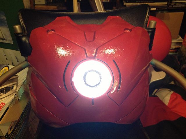
Video of the finished suit functions-


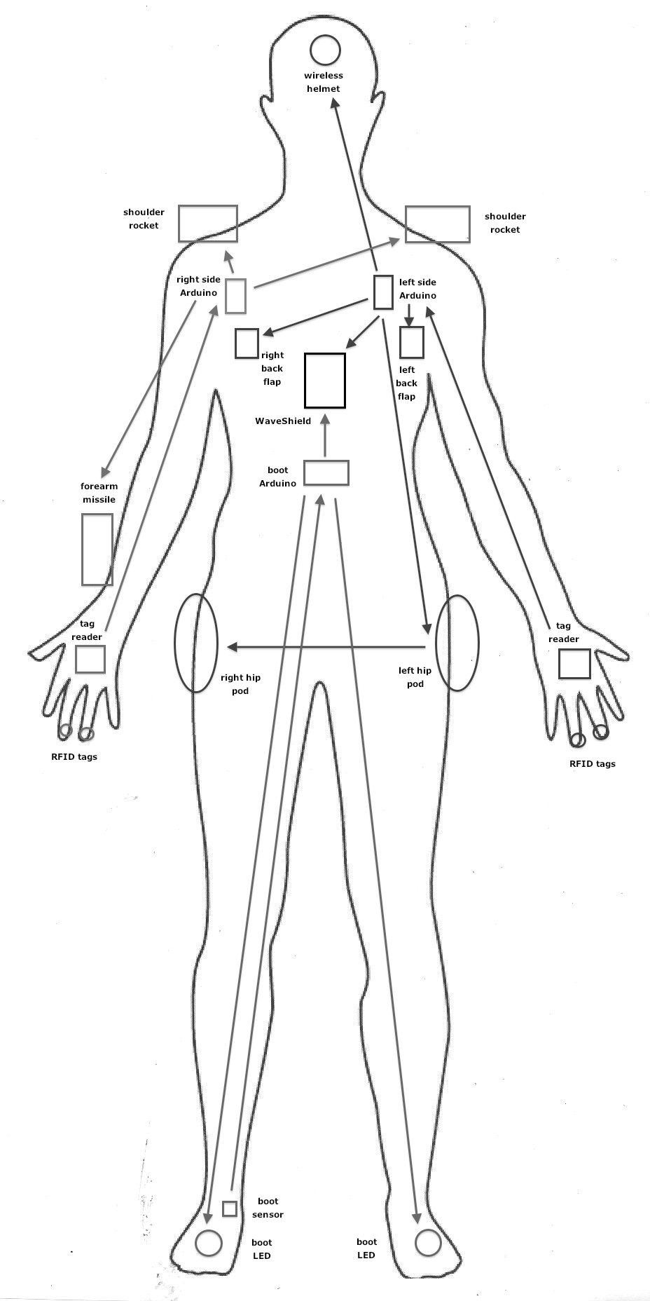
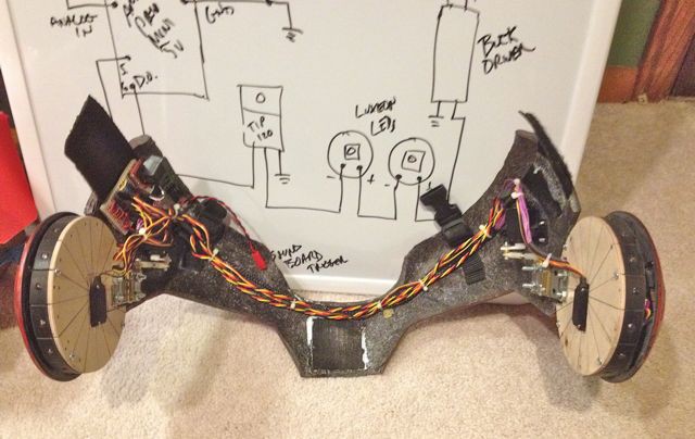
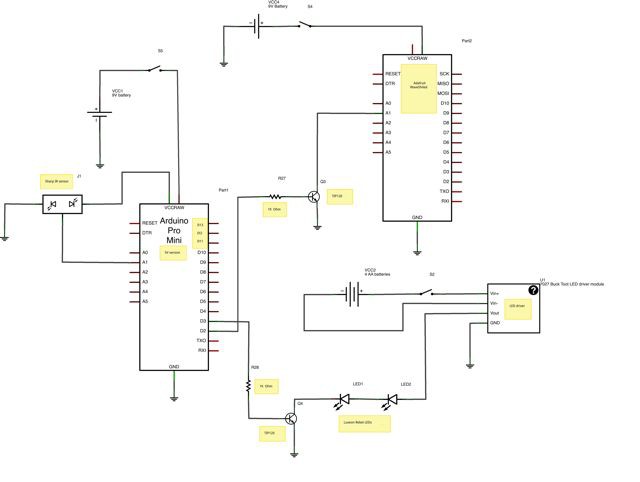
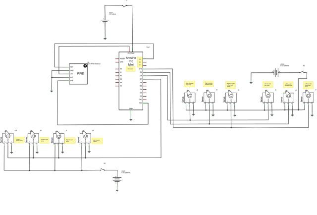
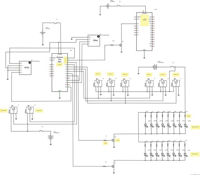
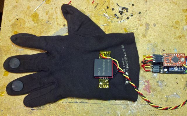
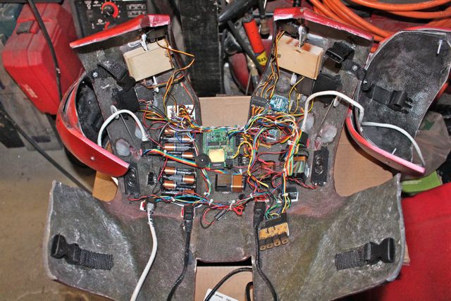
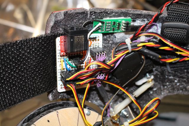
The suit is basically broken down into three systems: left side, right side and boots. The left hand has two RFID tags that trigger programmed sequences for the helmet, hip pods and back flaps. The right hand RFID tags trigger programmed sequences for the forearm missile and shoulder rockets. The boots have an infrared sensor that triggers the boot lights and sound effect as soon as the boot is lifted from the ground.

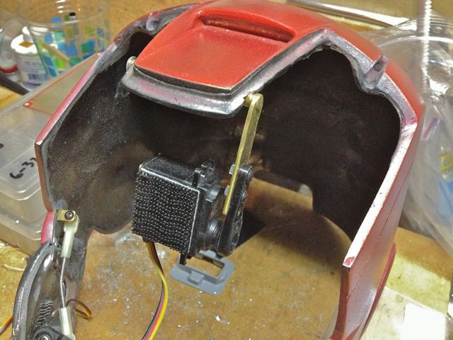
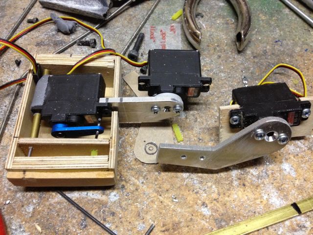
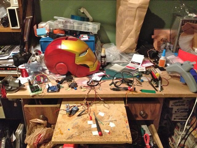
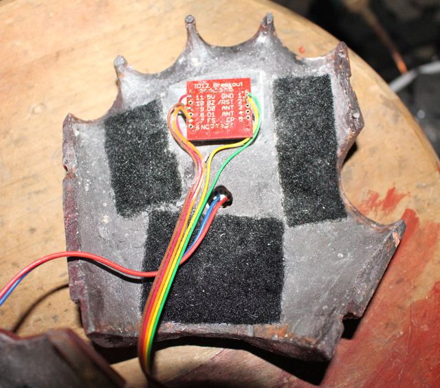
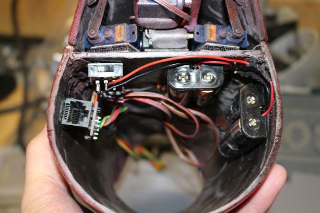
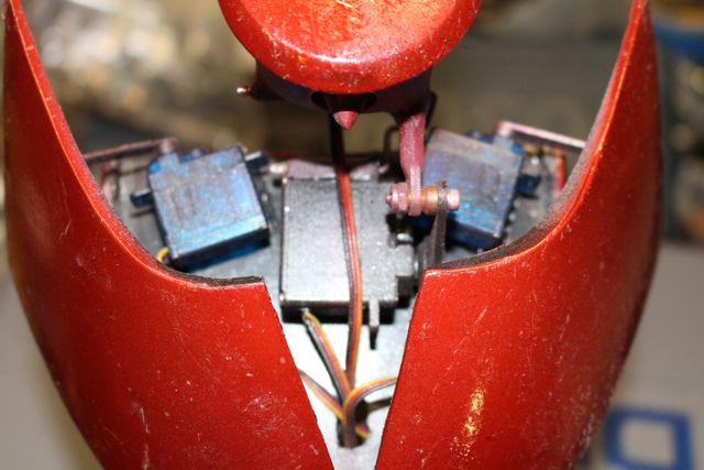
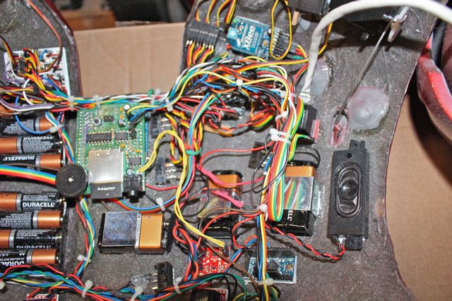
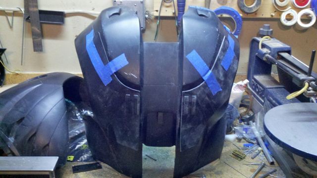
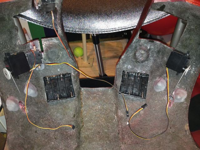
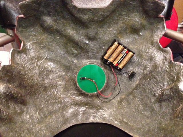
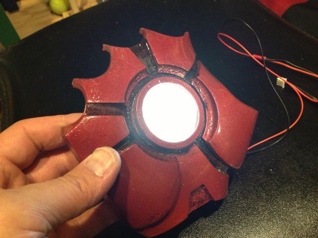
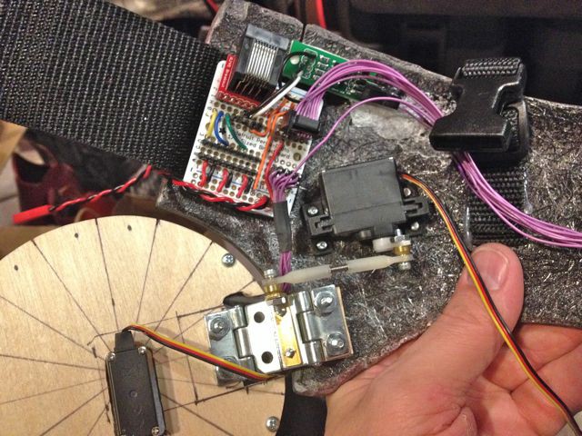
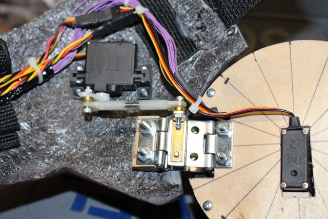
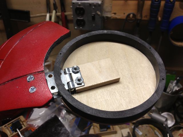
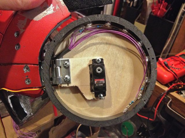
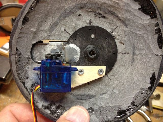
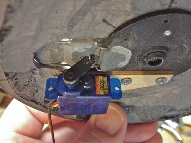
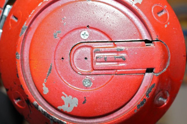
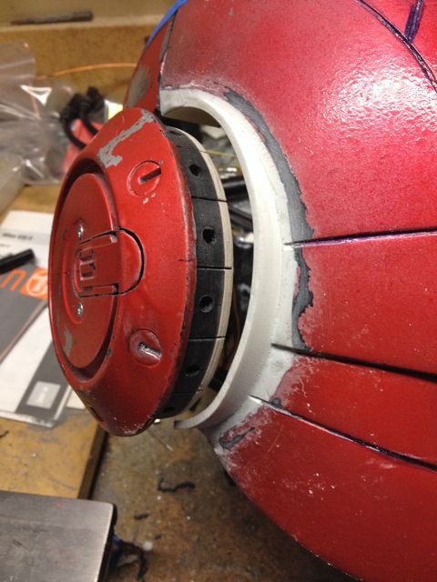
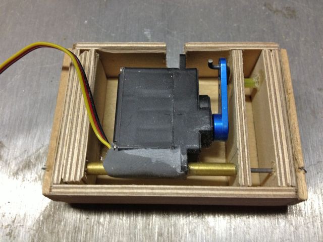
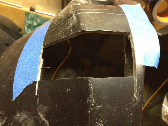
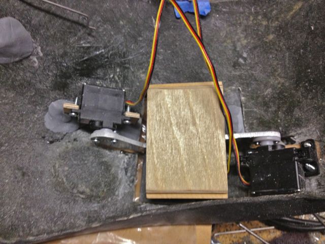
The single most difficult thing about this build is that the suit fits like a glove- there's no room in it! The helmet has less than 1/2" of space around the head, there's about 1" depth for the shoulder rocket pods and the hip pod area has less than 1" depth available so the packaging of the mechanics and electronics is really tight. Another issue is that there's almost no flat surfaces so mounting servos and hardware gets really interesting.

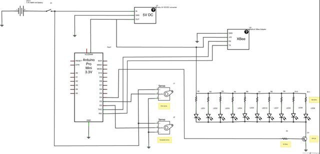
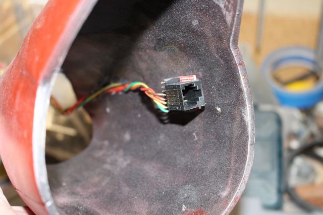
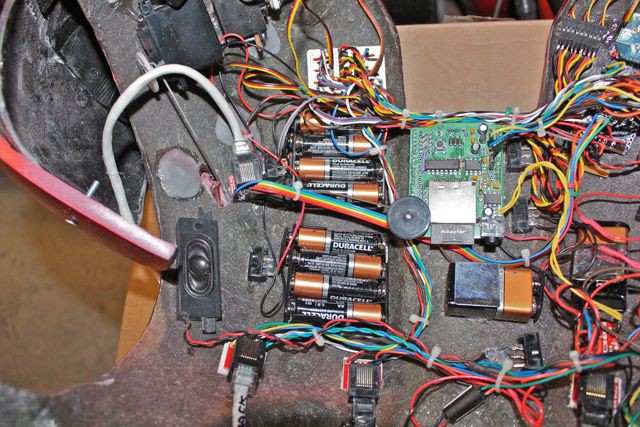
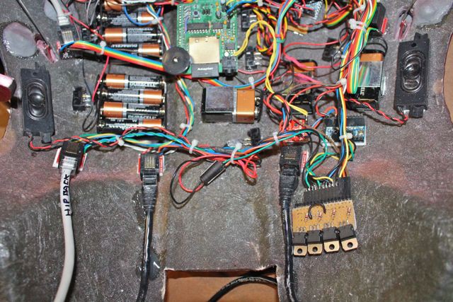
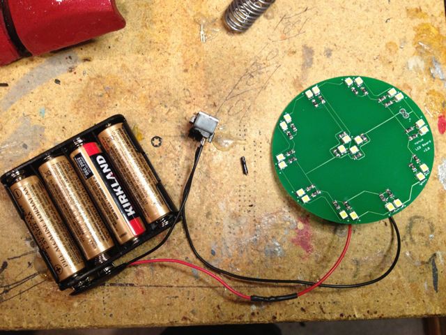
The system is Arduino based and uses four ProMinis- one for each side, one for the boots and one in the helmet. Since we wanted the helmet to be easy to take on and off we decided to make it wireless using XBee radios to send the control signals. For the point to point wiring running from the electronics mounted in the back to the arms and feet we used Ethernet cables and jacks so they could be easily disconnected. The sound effects for the boots are handled by a WaveShield that sits on a Arduino Pro.

Another issue with systems like this is the voltage and current requirements so we thought it best to power the servos separately using AA batteries, primarily for ease of availability if the suit is to be worn at conventions.

In the end this build was an enormous learning experience- it was a difficult build, somewhat frustrating at times and a real challenge to figure out ways to get the desired effects while making it as practical as possible and as convincing as possible. My house and garage looked like a hurricane had gone through it and deposited Iron Man parts everywhere. Many things didn't work as originally planned ( I think I revamped the helmet twice ) and I managed to fry a servo but in the end we stuck to it and it all worked out. :)

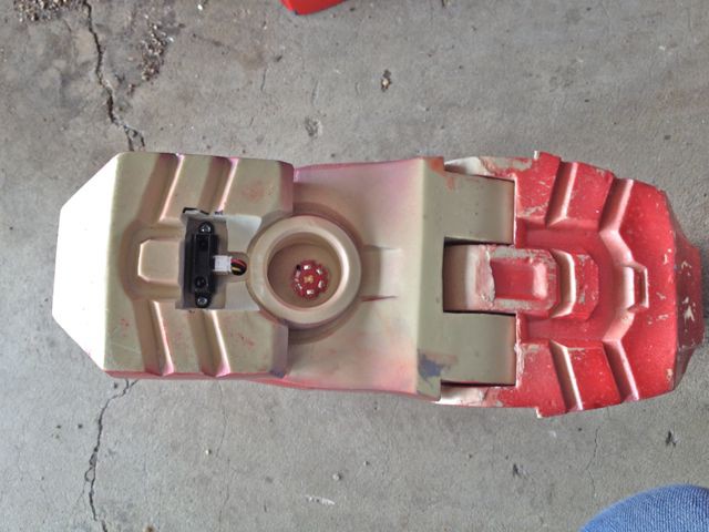
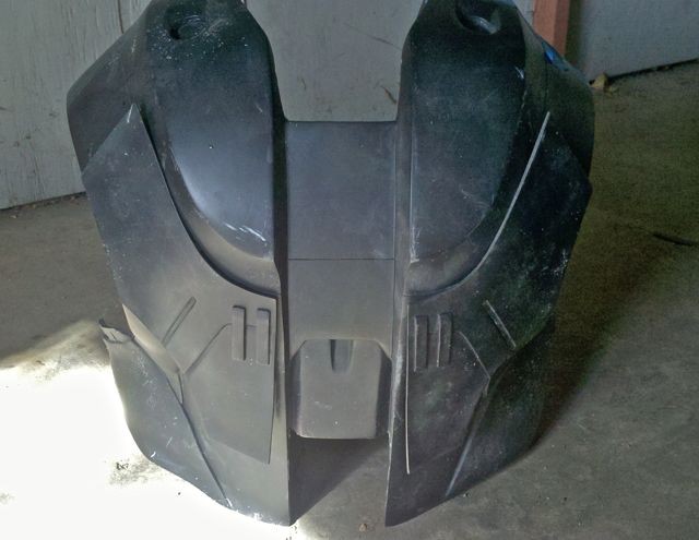
Please note that I do not manufacture Iron Man armor suits or helmet castings nor do I sell them. This particular set of fiberglass Iron Man armor belongs to my friend Greg who asked for my help in animating it. My friend Greg acquired the molded fiberglass suit and helmet castings from Clinton Hoines of Tundra Designs and they were modified to accept the animatronics. The boots and gloves came from Replica Prop Forum member Zabana.

  • 2 × ID-12 RFID tag reader Sparkfun part # SEN-08419 (LA version is replacement)
  • 2 × XBee Series 1 module Sparkfun part # WRL-11215
  • 2 × Adafruit XBee Adapter board Adafruit Product ID: 126
  • 2 × Arduino ProMini 328 5V Sparkfun part # DEV-11113
  • 1 × Arduino ProMini 328 3.3V Sparkfun part # DEV-11114

View all 27 components

  • Build log 12- boot schematic and code

    jeromekelty04/27/2014 at 02:25 0 comments

    Here's the schematic and code for the boots- it's pretty simple. The Sharp IR sensor inputs a value into the Arduino which triggers the Luxeon boot lights and the WaveShield to play an audio file.

    A larger version can be seen here.

    Here's the code-

    // these constants won't change:

    int triggerSensor = 1;            // the sensor is connected to analog pin 1
    int threshold = 750;              // threshold value to decide when the sensor input triggers
    int ledPin = 3;                        // control pin for LED
    int soundPin = 2;                   // control pin for sound board

    // these variables will change:
    int sensorReading = 0;          // variable to store the value read from the sensor pin


    void setup() {
    Serial.begin(9600);                      // use the serial port
    pinMode(ledPin, OUTPUT);         // sets the LED pin as an output
    pinMode(soundPin, OUTPUT);    // sets the sound pin as output
    digitalWrite(ledPin, LOW);            // turn off LED
    digitalWrite(soundPin, LOW);       // turn the sound off

    }

    void loop() {

    // read the sensor and store it in the variable sensorReading:
    int val = analogRead(triggerSensor);

    // if the sensor reading is greater than the threshold:
    if (val >= threshold) {

    Serial.println(val);
    digitalWrite(soundPin, HIGH);             // turn the sound on
    delay(10);                                              // wait ten milliseconds
    digitalWrite(soundPin, LOW);              // turn the sound off
    digitalWrite(ledPin, HIGH);                  // turn the LED on
    delay(2400);                                        // wait two seconds
    digitalWrite(ledPin, LOW);                   // turn the LED off
    }


    }

  • Build log 11- right side schematic and code

    jeromekelty04/26/2014 at 23:49 0 comments

    Here's the schematic and code for the right side. It's pretty similar to the left side, minus the XBee radio. The servos for the forearm rocket all receive the same signal- one of the servos that opens the side cover will need to be reversed rotation. Two of the servos that open the forward and rearward shoulder rocket covers will also need to have their rotation reversed as they receive the same signal as the servos on the opposite shoulder. 

    A larger image can be seen here.

    Here's the code for the right side-

    #include "Servo.h"                 // include the servo library

    Servo forearmServo;             // servos to move forearm missile
    Servo rearcoverServo;          // servo to move rear shoulder rocket pod cover
    Servo forwardcoverServo;    // servo to move forward shoulder rocket pod cover
    Servo podServo;                   // servo to move shoulder rocket pod


    int RFIDResetPin = 13;
    int servoPin1 = 7;                   // control pin for forearm missile servos
    int servoPin2 = 8;                  // control pin for rear shoulder rocket pod cover servo
    int servoPin3 = 9;                  // control pin for forward rocket pod cover servo
    int servoPin4 = 10;                // control pin for shoulder rocket pod servo


    //Register your RFID tags here
    char tag1[13] = "440085E77452";
    char tag2[13] = "440085FC330E";
    char tag3[13] = "440085F97840";
    char tag4[13] = "4400863914EF";


    void setup(){
    Serial.begin(9600);


    forearmServo.attach(servoPin1);              // attaches the servo on pin 7 to the servo object
    rearcoverServo.attach(servoPin2);          // attaches the servo on pin 8 to the servo object
    forwardcoverServo.attach(servoPin3);    // attaches the servo on pin 9 to the servo object
    podServo.attach(servoPin4);                    // attches the servo on pin 10 to the servo object
    forearmServo.write(45);                            // rotate the forearm servos to 45 degrees
    rearcoverServo.write(45);                         // rotate the rear cover servo to 45 degrees
    forwardcoverServo.write(45);                   // rotate the forward cover servo to 45 degrees
    podServo.write(45);                                   // rotate the left flap servo to 45 degrees


    pinMode(RFIDResetPin, OUTPUT);
    digitalWrite(RFIDResetPin, HIGH);


    }

    void loop(){

    char tagString[13];
    int index = 0;
    boolean reading = false;

    while(Serial.available()){

    int readByte = Serial.read();               // read next available byte

    if(readByte == 2) reading = true;        // begining of tag
    if(readByte == 3) reading = false;       // end of tag

    if(reading && readByte != 2 && readByte != 10 && readByte != 13){
    //store the tag
    tagString[index] = readByte;
    index ++;
    }
    }

    checkTag(tagString);            // Check if it is a match
    clearTag(tagString);              // Clear the char of all value
    resetReader();                       // reset the RFID reader
    }

    void checkTag(char...

    Read more »

  • Build log 10- wireless helmet schematic and code

    jeromekelty04/26/2014 at 06:48 0 comments

    Since there's very little room in the helmet the wireless system was powered by a single 7.4V NiMH battery pack. The digital servos used in the helmet are designed to be operated on 7.4V so a DC/DC converter is used to provide power for the Arduino, XBee and LEDs. 

    A larger image is available here.

    Here's the code for the helmet-

    #include "Servo.h" // include the servo library

    Servo faceplateServo;
    Servo chinServo;

    int ledPin1 = 4;                    // control pin for LED eyes
    int servoPin1 = 2;               // control pin for face plate servo
    int servoPin2 = 3;              // control pin for chin

    void setup() {

    faceplateServo.attach(servoPin1);         // attaches the servo on pin 2 to the servo object
    chinServo.attach(servoPin2);                // attaches the servo on pin 3 to the servo object
    faceplateServo.write(30);                      // rotate face plate servo to 30 degrees
    chinServo.write(95);                               // rotate chin servo to 95 degrees
    pinMode(ledPin1, OUTPUT);                 // sets the LED pin as output
    digitalWrite(ledPin1, HIGH);                   // turn on LED eyes

    Serial.begin(9600);
    }

    void loop() {


    // look for a capital A over the serial port and turn off LED
    if (Serial.available() > 0) {
    if (Serial.read() == 'A') {
    digitalWrite(ledPin1, LOW);                         // turn off LED eyes
    delay(500);                                                  // wait half a second
    faceplateServo.write(95);                           // rotate the face plate servo to 95 degrees
    chinServo.write(20);                                    // rotate the chin servo to 20 degrees
    delay(4000);                                                // wait 4 seconds
    chinServo.write(95);                                    // rotate the chin servo to 95 degrees
    faceplateServo.write(30);                           // rotate the face plate servo to 30 degrees
    digitalWrite(ledPin1, HIGH);                        // turn on LED eyes

    }
    }
    }

  • Build log 9- Left side schematic and code

    jeromekelty04/26/2014 at 06:39 0 comments

    Here's the schematic for the left side control system. There are a few notes on the diagram but it's pretty straightforward. When parts were purchased for the suit the ID12 tag reader was only available in a 5V version, which was powered by the Arduino. Since the servos are powered by a 6V battery pack it was easiest to just use a 9V battery for the Arduinos and 6V packs for the servos because you need to isolate the power supply for the Arduino due to the electrical noise generated by the servos.

    Now that the ID12 is available in a low voltage version it would be simpler to power everything from a 6V battery pack and use a 3.3V Arduino ProMini and use a 3.3V DC/DC converter to supply isolated power the Arduino.

    A larger image is available here.

    Here's the code for the left side-


    #include <NewSoftSerial.h>
    #include "Servo.h"          // include the servo library

    Servo podServo;             // servo to move hip pods
    Servo leverServo;            // servo to move hip pod levers
    Servo rotateServo;         // servo to rotate hip pods
    Servo leftflapServo;        // servo to move left back flap
    Servo rightflapServo;     // servo to move right back flap

    NewSoftSerial mySerial = NewSoftSerial(2, 3);

    int RFIDResetPin = 13;
    int ledPin1 = 6;                  // control pin for left hip pod LEDs
    int ledPin2 = 5;                 // control pin for right hip pod LEDs
    int servoPin1 = 10;            // control pin for left flap servo
    int servoPin2 = 11;            // control pin for right flap servo
    int servoPin3 = 9;            // control pin for pod servo
    int servoPin4 = 8;            // control pin for lever servo
    int servoPin5 = 7;            // control pin for rotate servo
    int soundPin = 12;           // control pin for flare sound

    //Register your RFID tags here
    char tag1[13] = "440085E77452";
    char tag2[13] = "440085FC330E";
    char tag3[13] = "440085F97840";
    char tag4[13] = "4400863914EF";


    void setup(){
    Serial.begin(9600);
    mySerial.begin(9600);

    podServo.attach(servoPin3);                 // attaches the servo on pin 9 to the servo object
    leverServo.attach(servoPin4);               // attaches the servo on pin 8 to the servo object
    rotateServo.attach(servoPin5);             // attaches the servo on pin 7 to the servo object
    leftflapServo.attach(servoPin1);             // attaches the servo on pin 10 to the servo object
    rightflapServo.attach(servoPin2);         // attaches the servo on pin 11 to the servo object
    podServo.write(155);                              // rotate the pod servo to 135 degrees
    leverServo.write(145);                            // rotate the lever servo to 135 degrees
    rotateServo.write(165);                          // rotate the pod rotation servo to 170 degrees
    leftflapServo.write(170);                         // rotate the left flap servo to 170 degrees...

    Read more »

  • Build log 8- electronics

    jeromekelty04/24/2014 at 18:58 0 comments

    The electronics for this suit aren't really that complex once it's broken down into separate systems. The reason I wanted to make the left side/right side and boots separate systems was so they could be run at the same time and if one system went down the rest of the suit would still operate. 

    The left side takes the RFID tag input from two fingers on the left hand and then the Arduino will operate either the helmet functions (via the XBee radio) or it will have the hip pods and back flaps run through a programmed sequence. 

    The right side takes the RFID tag input from two fingers on the right hand and then a second Arduino operates either the hip pods or shoulder rockets, depending on which tag is read. If the hip pods are selected then the WaveShield is also triggered to play a sound effect.

    The IR sensor in the right boot sends a signal to another Arduino that operates the lights for the boots and triggers the WaveShield to play a sound effect.

    For testing purposes I glued RFID tags and a tag reader to a glove to get an idea as to how easy it would be to operate, since the tag reader can only read one tag at a time. Reading two tags at the same time gives zero output. I was worried that since the fingers were in close proximity to one another this could be a problem, but it turns out it worked just fine. 

    The tag reader was then mounted to the inside of the fiberglass suit glove shell using adhesive foam tape. The back side of the board was then taped over to protect it and the lead wires. The glove clam shells fit over a batting glove so the wearer's hand never comes in contact with the board.

    The gloves have extension leads that connect to the gauntlets, which have Ethernet jacks for connecting to the Ethernet cables that run through the arms. The left gauntlet is pretty much empty while the right gauntlet has AA battery holders as well as a small connector board for the servo wires.

    The servo wires are run through a hole in the gauntlet base plate.

    The three Arduino ProMinis are mounted in the back of the upper torso section along with batteries and power switches for each system. The WaveShield sits atop the Arduino Pro in the center. The transmitting XBee radio for the helmet is visible in the upper corner. There are also several Ethernet jacks visible- two for the arms, two for the legs and one for the Ethernet cable that runs to the hip section. Also visible is a board that has a few transistors on it- these take the signals from the Arduinos and turn on the boot lights and trigger the sound effects via the Wave Shield. THe WaveShield output is boosted by a small amplifier board. There is a small breadboard PCB in the upper corner that has connectors for the shoulder rocket servos and back flap servos. The two speakers were salvaged from an old monitor.

    And that is a boatload of wiring! The boards are secured using foam tape as it holds them securely but they can still be removed and if wires get pulled nothing will get damaged. The Ethernet cables were also secured using hot glue a bit away from the connectors in order to provide some strain relief. 

    If I was to do it again I would probably create a single board down the center and have the Arduinos socketed along with a socketed transistor board using SMD transistors. I would also have the servo connectors on the center board.  That would go a log way toward cleaning up the wiring.

    The hip pod section uses a small breadboard PCB with an Ethernet connector to route the signals for the servos and LEDs in the pods. There is a small transistor board that is used to turn on the pod LEDs. The wires fro the LEDs were run through the back of the pods near the hinge and heatshrink tubing was used protect the wires from potential damage caused by hinge movement. 

    Finally the AA batteries that provide power to the hip pod servos were mounted to the inside of the chest section near the chest light along with a switch. A power lead with a JST connector was run...

    Read more »

  • Build log 7- boots

    jeromekelty04/23/2014 at 04:52 0 comments

    We knew that we wanted to boots to light up and make a robotic clanking sound while walking. I figured the easiest way to trigger this effect was to use a distance sensor on the underside of the boot- in this case the Sharp GP2D120XJ00F IR sensor. The sensor reads the distance from the boot to the ground and then a threshold value is set in the code so when the value exceeds the threshold the sensor tells the Arduino to turn on the light and activate the sound. Simple!

    A cavity was carved out of the bottom of the boot with a Dremel tool and the sensor was mounted in place. A hole was drilled through for the sensor wires as well as the wires for the high power Luxeon LED. The wires for these were bundled together and a connector was soldered on so they could be easily disconnected from the wires that ran down through the legs of the suit. Only one sensor is needed to trigger the Arduino so the sensor was mounted in the right boot since Greg begins walking with his right foot first.

  • Build log 6- back flaps

    jeromekelty04/23/2014 at 04:35 1 comment

    The back flaps were very straight forward to animate. The flaps were first held in place with tape in order to locate the hinges.  

    Hinges were constructed using brass rod and tube and they were epoxied to the back of the flaps. The hinges were then mounted to the back of the upper torso by drilling holes and using epoxy putty to bond them in place. 

    Control horns were mounted to the flaps and slots were cut in the upper back torso section so the control horns and connecting rods could fit through. The servos to move the back flaps were mounted to the inside of the upper back torso using high strength Velcro. 

    Finished!

  • Build log 5- lights!

    jeromekelty04/23/2014 at 03:11 0 comments

    What Iron Man suit would be complete without lights? For the chest light I created a simple PCB in EAGLE and soldered on the surface mount resistors and LEDs. The finished PCB was wired up and mounted behind the translucent chest piece.

    With the hands we lucked out and didn't need to build the lighting system from scratch as Greg already had a repulsor light and sound system that was donated by a friend.

  • Build log 4- hip pods

    jeromekelty04/22/2014 at 18:55 0 comments

    The hip pods were something I kind of threw in- Greg wasn't expecting it. Heck, I wasn't expecting it! Greg now knows me well enough to know that I tend to first say it can't be done or isn't probable and then fifteen minutes later I figure it out- that's just my M.O. The hip pods are a perfect example of this. I first looked at the suit and said "no way." But of course it bugged me because it would be so cool to have them move... So first I figured out how to make them pop out of the hip section. Then I thought it would be great if they could rotate. Then I thought, well heck- might as well make the lever on the cover slide and have them light up! 

    To make the pods pop out I took two small hinges and welded them together to make a parallelogram linkage and then added a micro servo to move the linkage. The finished mechanism is very low profile. Getting the pods to fit right was tricky because the fiberglass hip section with was molded as one piece so everything had to be cut apart and reconstructed. The faceplate of the pod was cut away and hollowed out to make a shell and a housing was made from ABS pipe. A backing plate was cut from birch plywood.

    Several ideas were tried for the pod rotation system but ultimately the faceplate was driven directly by a servo as that took up the least amount of space. The rotation servo is mounted to a piece of plywood that is bolted to the hinge assembly. LEDs were mounted in the ABS ring to simulate the flares.

    A servo wheel is mounted to the rotation servo and it drives the pod faceplate. To make the lever on the faceplate slide open a sub-micro servo is mounted to a plywood plate that is attached to the servo wheel. The servo output arm has a small slot cut in it and it is attached to the sliding lever using with a small section of music wire that is epoxied in place. The lever slides on a small hinge made from music wire and brass tubing- the hinge is attached to the large servo wheel. As the servo lever moves the hinge rotates slightly outward and the lever slides open. This particular mechanism required a lot of trial end error fitting to get it to move smoothly with very little friction.

    Since the suit hip section had been cut away in order to use the pods we had to reconstruct the flanges on the back hip section. Sintra sheet was cut and formed to shape and was epoxied in place and then the seams were filled in with Apoxie Sculpt. In the end the hip pods worked really well and I'm glad we went to the trouble of adding them!

  • Build log 3- shoulder rocket pods

    jeromekelty04/22/2014 at 05:49 0 comments

    We really wanted shoulder rocket pods- in a big bad way. We just thought it would be so cool to see them open up and unfold like in the movie. The trouble was there was no way they could ever fit in there and perform in a similar fashion- the suit simply didn't have the necessary internal volume. There is about one inch of usable depth in the shoulder area. Those darn visual effects again...

    Once I began taking measurements with Greg in the suit I wasn't so sure it could be done. I think I probably sketched a couple hundred designs trying to figure out a way to have the pod raise up and fold over. This was a key feature I really, really wanted. I didn't want to have a pod that opened like one of those flip up car headlamps. I knew I couldn't have it perform like in the film with the entire shoulder section moving but I felt I could get something that looked really cool. 

    I finally settled on having a section of the shoulder split into two panels- one rotating forward and one rotating backward. This would give a decent sized opening for a proper size rocket pod. The big trick was making the pod an open box so the servo could hide inside it- without that there was no way it would ever fit in the shoulder cavity.

    The pod is constructed of birch plywood and pivots are fabricated from brass tube and music wire. As the servo arm rotates the rear of the rocket pod is pushed away from the servo. The pod servo is mounted to an Aluminum plate that is attached to the forward shoulder panel servo. The rear panel servo has a similar Aluminum plate attached to it. The plates have threaded holes in them for attaching the shoulder panels to them with small brass angle brackets. The holes in the brass angle brackets are slightly slotted to allow for a small range of height adjustment of the shoulder panel.

    There was an enormous amount of trial and error fitting as once the shoulder was cut out of the fiberglass suit there would be no turning back- we had to be right on the money the first time. The panel openings were taped off and cut out with a Dremel tool and then the servos were mounted inside the shoulder area using plywood mounts epoxied into place. Getting the panels to fit just right was a real challenge!

View all 12 project logs

  • 1
    Step 1

    A few notes and tips concerning the use of servos in the build:

    The servos listed are just what we used based on speed, power, durability and cost requirements. I would definitely recommend using metal gear servos with ball bearings. Nylon geared servos strip very easily, especially the micro and sub-micro variety.

    Several of the servos will need to be changed to reverse rotation since the right and left side of various suit parts receive the same control signal. There are three options- use digital servos (easiest but most expensive), have the supplier change the rotation (Servocity.com does this) or change the rotation yourself by taking the servo apart and reversing the motor lead wires and the outer two pot wires. I changed them on the micro servos for the shoulder rockets and hip pods myself since I'm cheap. :)

    We did elect to use high voltage digital servos in the helmet for the power they provide and the fact that their speed can be adjusted using a servo programmer. The servos for the hip pod sliding panels and gauntlet side panels also used digital servos since they needed to be powerful and swapping the wires on sub-micro servos can be really tricky. The other reason was because the standard sub-micro servos use nylon gears and we wanted to use metal gears for durability.

    The servo position values in the code would probably need to be altered for another build since no two Iron Man suits are alike. The key when doing this is to make small changes in the values while paying attention to make sure the servos don't ever stall, as they can be easily damaged. If a servo does stall immediately turn off the power to the servos and make adjustments to the code.

  • 2
    Step 2

    Notes about mechanics and suit construction:

    Greg's suit is molded fiberglass. It is unlikely that a foam suit would be rigid enough to support the animatronic systems without some sort of reinforcement, especially in the shoulders as a large area has to be cut away. 

    It would also be best to have a finished assembled (but not painted) wearable suit before adding any animatronic system. It is important to know exactly how much room you have to work with and how it fits the suit performer before adding animatronics. 

    There are lots of different ways the mechanics of this suit could have been constructed. We tried to use readily available materials found in hobby shops and hardware stores whenever possible to save time and money. Items such as the shoulder rocket pods and hip pod hinge assemblies could easily be 3d printed if so desired.

  • 3
    Step 3

    Notes about tools and materials used:

    ProPoxy 20 is awesome stuff. When making the brass tube pivots for the shoulder rocket pods it was easiest to glue the brass tube to the servo casing with superglue ( I use Gorilla glue with a spray accelerator) and then mold some ProPoxy 20 around it- this is an easy way to make simple hinges that are very durable. 

    Adafruit Perma-Proto boards are really great; I highly recommend using them to mount transistors, servo connectors, regulators and resistors. Anything you can do to clean up the wiring in the suit is time and money well spent. If I was to do it over again I would design a custom PCB in order to clean up the wiring in the back torso.

    As far as tools go, most all of the work was done with basic tools; a scroll saw to cut the plywood, soldering iron, wire cutters, pliers and a Dremel tool. A bit of fiberglass work was done in the helmet and for this I really like epoxy resin- I use West Systems epoxies. Epoxy resin doesn't smell and it's a lot tougher than polyester resin. The West Systems epoxy resin also has an incredibly long shelf life and it's super easy to mix if you use their metered pumps.

View all 3 instructions

Enjoy this project?

Share

Discussions

ActualDragon wrote 02/02/2017 at 16:31 point

holy crap, are you crazy man?!?! why isin't this in the scifi contest

  Are you sure? yes | no

jeromekelty wrote 02/02/2017 at 16:34 point

I am crazy. :) This was in the last SciFi contest. I do have another good project to enter in this year though.

  Are you sure? yes | no

ActualDragon wrote 02/02/2017 at 16:38 point

well, there goes my chances- this project is great, whatever you enter, i hope you win

  Are you sure? yes | no

Mike Hinkle wrote 09/28/2014 at 17:29 point
Great project! Would you like to show it off at the Houston Mini Maker Faire on 11/1? The crowds would love it!

  Are you sure? yes | no

niazangels wrote 04/27/2014 at 09:33 point
I love what you've got going, there! You really seem to have a LOT of free time :D
You inspired these Ironman renderings :) http://hackaday.io/project/895/log/1848

  Are you sure? yes | no

jeromekelty wrote 04/27/2014 at 15:29 point
Thanks- that's awesome! I have three kids so the only way for me to work on my projects is to stay up late. And there were an awful lot of late nights on this project! :)

  Are you sure? yes | no

betosantos1.personal wrote 04/23/2014 at 18:49 point
Gostaria de ter acesso aos circuitos eletronicos (com os nomes dos componetes) de toda parte eletronica!!
Muito obrigado!!

  Are you sure? yes | no

betosantos1.personal wrote 04/23/2014 at 18:48 point
Parabéns pelo projeto! Muito bom!!

  Are you sure? yes | no

jeromekelty wrote 04/24/2014 at 04:31 point
Thanks! Working on parts list and schematics now. :)

  Are you sure? yes | no

Similar Projects

Does this project spark your interest?

Become a member to follow this project and never miss any updates