 zakqwy
First, a TL;DR picture illustrating the ramblings of this far-too-long log entry:
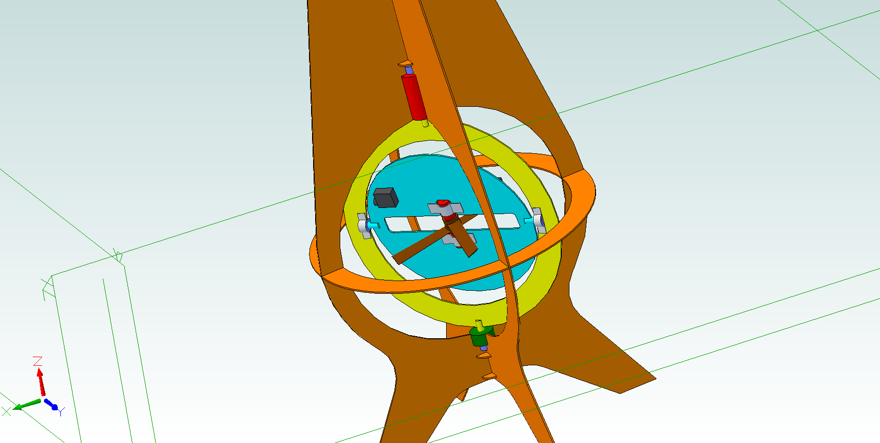
Color scheme:
- Orange: CFRP frame
- Red: brushless motors
- Gray: aluminum motor brackets
- Dark gray: servos
- Purple: radial/thrust bearings
- Brown: propellers
- Cyan: thrust plate
- Yellow: pitch ring
- Green: slip ring
I've had a few thoughts since my last post, most of which are related to actuation of the gimbal axes. As I discussed previously, the gimbal mechanism will have two degrees of freedom: rotation around the GimbalBot's vertical axis, and rotation perpendicular to that axis to control what I referred to as the 'severity' of the corrective thrust vector. I also mentioned that the travel time from one control point (rotation angle + severity angle) to another should equalize both degrees of freedom so that the gimbal doesn't hit its rotation and wait for the angle to be right.
We'll call rotation of the gimbal
around the GimbalBot's vertical axis Rho, while severity angle (thrust vector direction?) with
respect to the vertical axis is Theta. Theta is zero when the thrust is
in line with the GimbalBot's vertical axis, and Rho is zero at an
arbitrary point around the GimbalBot's body (i.e., we'll usually just
consider it relative to a previous value). To move from one control
point to another, the actuator control circuitry needs to determine the
shortest possible path; also, the path that minimizes severity angle
(err, Theta), since we'll assume our fancy brushless thruster motors
can't modulate speed very quickly (don't even think about suggesting
swash plates!). Either way, in some cases the controller will move Theta
through 0 degrees, and in other cases it won't. For example:
- Theta is 15 degrees, and Rho is 0. The control system needs to increase Theta to 20 degrees and rotate Rho to +30 degrees. To accomplish this in one second, GimbalBot would elevate Theta at 5 deg/sec and rotate Rho at 30 deg/sec.
- Theta is 15 degrees, and Rho is 0. The control
system needs to keep Theta at the same value but rotate Rho to +160
degrees. In order to minimize the off-axis thrust (that would presumably
cause a severe flight path upset that would require additional
correction), Rho would rotate at -20 deg/sec and Theta would rotate at
-30 deg/sec.
So how do we do this? Should the control system, knowing the maximum actuation speed for Theta and Rho, attempt to optimize for minimum A --> B actuation time? Or should we limit the maximum Delta Rho to some arbitrary value like 90 degrees, past which we flip-flop Theta instead of performing a larger Rho change? Either way, one thing is clear: we want Rho to only be relative to previous values of Rho. Eventually we'll tie it in to some arbitrary direction so GimbalBot has a definite 'front' and 'back', but in general it will need to be able to spin freely. That gives us a significant design constraint.
Rho needs to rotate continuously through 360 degrees, otherwise GimbalBot's response rate to disturbances will vary depending on its absolute rotation. I suppose we could just use really long wires that eventually get wrapped around the gimbal after a few minutes of flight time (kidding), but the real solution here is to use a proper rotary electrical joint, generally called a slip ring (http://en.wikipedia.org/wiki/Slip_ring). Hmmm...
Where does the slip ring get mounted? Well, looking at the v01 sketch, the rotary actuator that controls Rho could be mounted above the gimbal assembly, and the slip joint mounted directly opposite at the very bottom of the unit. Provided the slip ring has a reasonably small cross sectional area, this hopefully won't disturb the thruster's air flow too much. Electrical wires to the stationary side of the slip joint would run around the perimeter of the frame and need to be nicely tucked -- again, to minimize air flow disturbance to the thruster.
So this might end
up constraining our design a bit, as slip rings are only available in
certain sizes and current ratings. Specifically, I could see there being
better weight:current rating and cross sectional area:current rating
designs; we want to minimize both of those ratios without building
something TOO big. In any case, what exactly do we need to get into the
continuously rotating portion of the gimbal, from an electrical
perspective?
- Thruster: I'm planning to use two brushless motors of some type (probably, as Curtis suggested, from the quadrotor scene). We'll need to give them power and individual control signals, since their relative rotation can be used to affect the rotational orientation of the device (NOT to be confused with Rho; we'll need another Greek letter for this, probably). Assuming I mount the electronic speed controllers on the gimbal plate itself next to the motor, that means four conductors total: ground, power, and two signals.
- Theta control: Theta doesn't need to rotate through 360 degrees (thank goodness), but it does need to be mounted on the gimbal ring that can rotate freely through the slip ring. Additionally, I'm hoping to use an opposing pair of small servos for Theta actuation; that will improve the assembly balance and reduce the torque transmitted around the ring itself. So... assuming the servos need to be controlled independently (so we can tweak starting position and so forth), that's another pair of signals assuming they share power with the thruster motors.
- Other
stuff? Will I need encoders? If Rho control uses a servo modified for
continuous rotation, it will need a shaft encoder to return relative
position; however, that can be mounted on the GimbalBot frame. Will I
need position sensing for Theta? Using servos should keep that
self-contained... we'll go with 'no' at this point.
Six conductors. Seems like that slip ring would get spendy, or at least large. More importantly, unless I use a mercury-wetted device, I'm guessing the carbon brushes inside a slip ring introduce at least some electrical noise. Will that cause issues with the servos or thruster RPM control? I'd rather not have to worry about it. What if I just send power at sufficient amperage through the slip ring and run the signals through a short-range RF link? I could put a beefy filtering cap on the receiver circuit to minimize noise on its power rail, and low power RF stuff should be pretty small and simple (while being plenty fast).
So here's the question (amongst many others): if I go wireless, what's my protocol? I'd prefer to use off-the-shelf stuff for simplicity. I've heard great things about Xbee; plenty of bandwidth. Will the continuous rotation cause issues with RF signal polarization angle? Can't afford to lose signal at specific Rho values! What about processing: should I put an ATtiny (or some other small microcontroller) on the gimbal itself to convert the wireless data stream into discrete servo outputs?
Oh yeah, motor details: Rho actuator will likely be a brushless motor with an encoder and a gearbox, or a servo (if I can find one that's nice and symmetrical). Added bonus if it's got a built-in thrust bearing so I can directly run the shaft into the unit. The servos need to be sized for speed and torque rating; note that I haven't done anything with the linkage yet, either. I might add another pitch ring perpendicular to the first (supported with gussets, etc) and the servos will run their linkages into that. Either way, I'm guessing I'll need some kind of linearization equation built in to the servo actuation since the linkage will be offset. Anyone that knows something about linkages care to weigh in?
As always, feedback is more than welcome. I've got a bit of experience with servos, but haven't putzed around with short-range small-scale wireless stuff. Or brushless motors. Or linkages. I don't want to spend the next month chasing down connectivity issues and pitch ring binding problems!
Discussions
Become a Hackaday.io Member
Create an account to leave a comment. Already have an account? Log In.