Jorj Bauer
-
Phase 5: regroup and rebuild
10/05/2016 at 00:33 • 0 commentsFaster motors, with more torque. Okay, how do we do that?
Well, faster is achievable with bigger wheels. I bought mounts for roller blade wheels last year, and also bought wheels up to 90mm in diameter.
The model is about 25 lbs., or 11.4 kg.
I'd like it to move at a minimum top speed of 3 mph. Preferably 4.5, so it can catch up to people walking.
And that's the end of what I know.
Reading about choosing motors for robots, I found many pages outlining the relationship between acceleration, velocity, wheel size, motor RPM, stall torque, and whatnot. It took me a while to figure out what all of the pieces were that I didn't know, but eventually I came to the conclusion that I wanted a 12v motor, at about 300rpm, with 77kg/cm stall torque (3.77N/m, 33.4 lb-in).
The motors I'm using are 30kg/cm stall torque - less than half what I want. That jives very closely to what I see. The Dalek moves at a calculated 1.8 mph, which is about half of what I want. Great, I'm getting somewhere!
So, much scouring the Internet, I really didn't find motors that fit the bill. I found a pair that were slightly more powerful than what I'm using now, but they're also *longer* - I'd have to build a more elaborate mount system for them, because they won't fit in the current mounts under Bob. Rats.
And this is where Bob sat for about a month.
One of the things I love about Hackaday is the inspiration from other peoples' projects. I obviously have a lot of projects that are running concurrently, all the time; most of them are sitting and waiting for inspiration, money, or time. Sometimes all three.
So when I'm stymied on motors for Dalek Bob, and a post like An Open Electric Wheelchair comes to Hackaday - Eureka! - I'm suddenly thinking about how hoverboard wheels have the power I need, with compact mounts because they're hub motors.
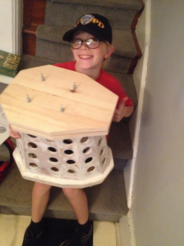
Order one hoverboard just to disassemble it: check.
Organize an 11-year-old family member to "test" the hoverboard before disassembly: also check. :)
If I'm going to use these brushless 36v DC motors to drive Bob, I'm going to need new control circuitry. The old motor controller is out the door. As is the 12v power system. Thinking through the cascading changes, I've got a lot of details to address.
Converting from 12v to 36v also means building a new 12v distribution system for the shoulder motors, and continuing to power the Arduinos as-is. I'll need a new mount for the battery itself; two new brushless motor controllers; a new power relay interface (I really like a hard off switch); a new circuit breaker, as we're talking about potential draws up to 20A, if I push these motors hard. Oh, and I had already hacked the heck out of the power switch the first time around to make it fit, so rewiring the power switch might just mean replacing it.
Lots of parts on order! We'll see what happens this weekend when everything arrives...
-
Phase 4: Assessing the Damage
10/02/2016 at 17:30 • 0 comments2014's showing was essentially damage-free. In 2015, LIWhoCon moved to a new hotel which had some challenges. Of note:
Trips on and off the elevators didn't help. That's the cause of the lost rollers on the base. I don't have a good solution for this at the moment; I'm just going to take more spares.The wire antenna on the Wii controller broke off. It takes a lot of abuse.
![]()
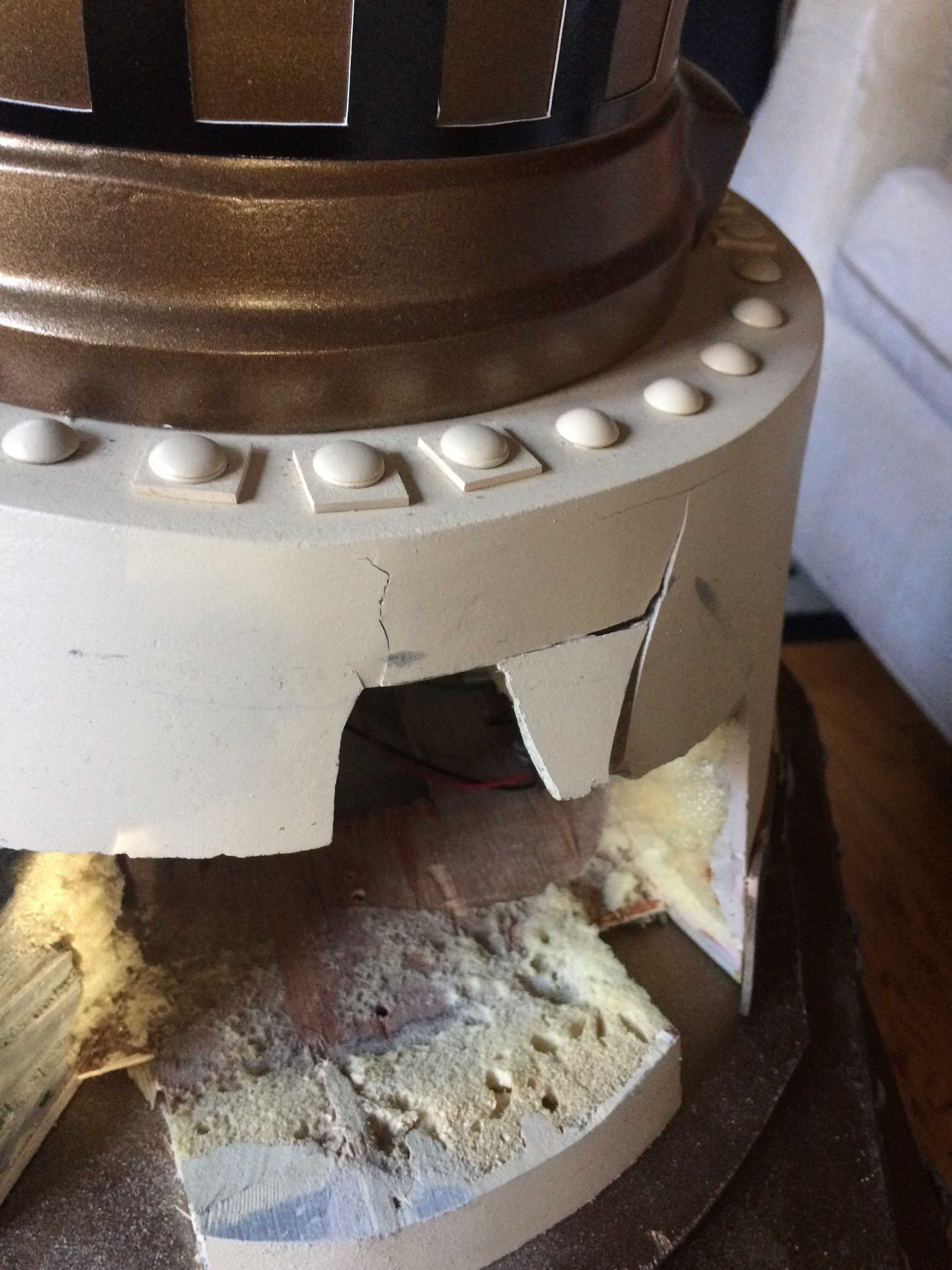
The gun stalk took some good hits - some because of spinning the head around in to things, and some from people just accidentally hitting it. This nicked the paint job on the gun stalk, and cracked the collar pretty badly.
The gun repainting was simple; some light sanding, re-priming, re-painting, re-clear coat-ing. And after 2015, it chipped again; I'll have to repaint it again this year.
The collar, I punted on. Much of that damage is hidden behind the gun box. I pushed it all back in to alignment and superglued it. Good enough for now.
But the best damage of all was due to the long stretches of hallway - particularly in 2015. (Bear with the long version.)
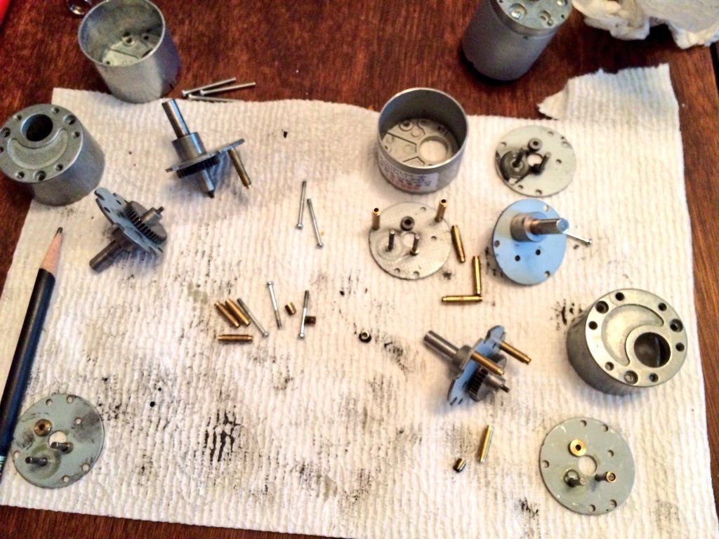
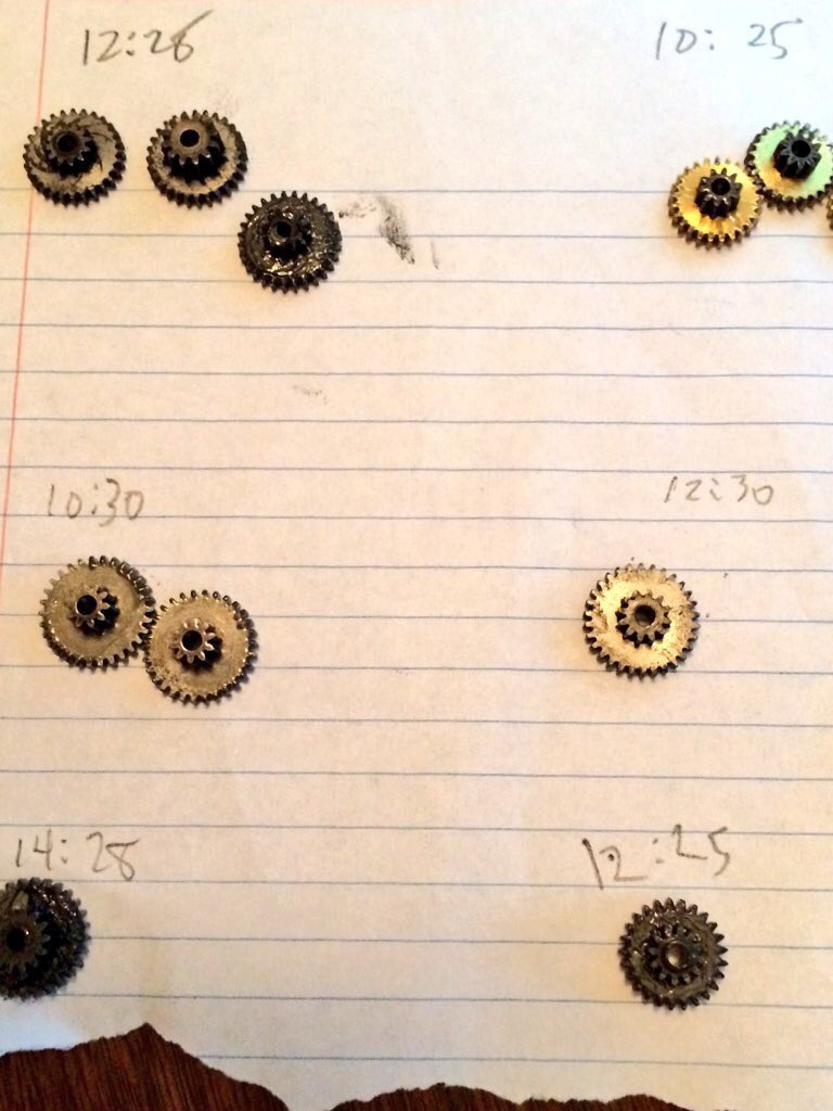
The motors weren't quite matched, and the dalek drifted a bit. Jake found this hard to compensate for, so I pulled apart all of the gearboxes for all of the motors I had to try to best re-match them.
![]()
![]()
I rebuilt the two with gears that matched a little better, and I'm sure all of this stressed the heck out of the components. Remember that the top speed of this thing is under 2 MPH; less than walking speed. I may have built a slightly lower gear ratio so that the Dalek would travel a little faster; I don't actually remember. I know that was one of my goals, and I remember testing it. I just don't recall where I left it.
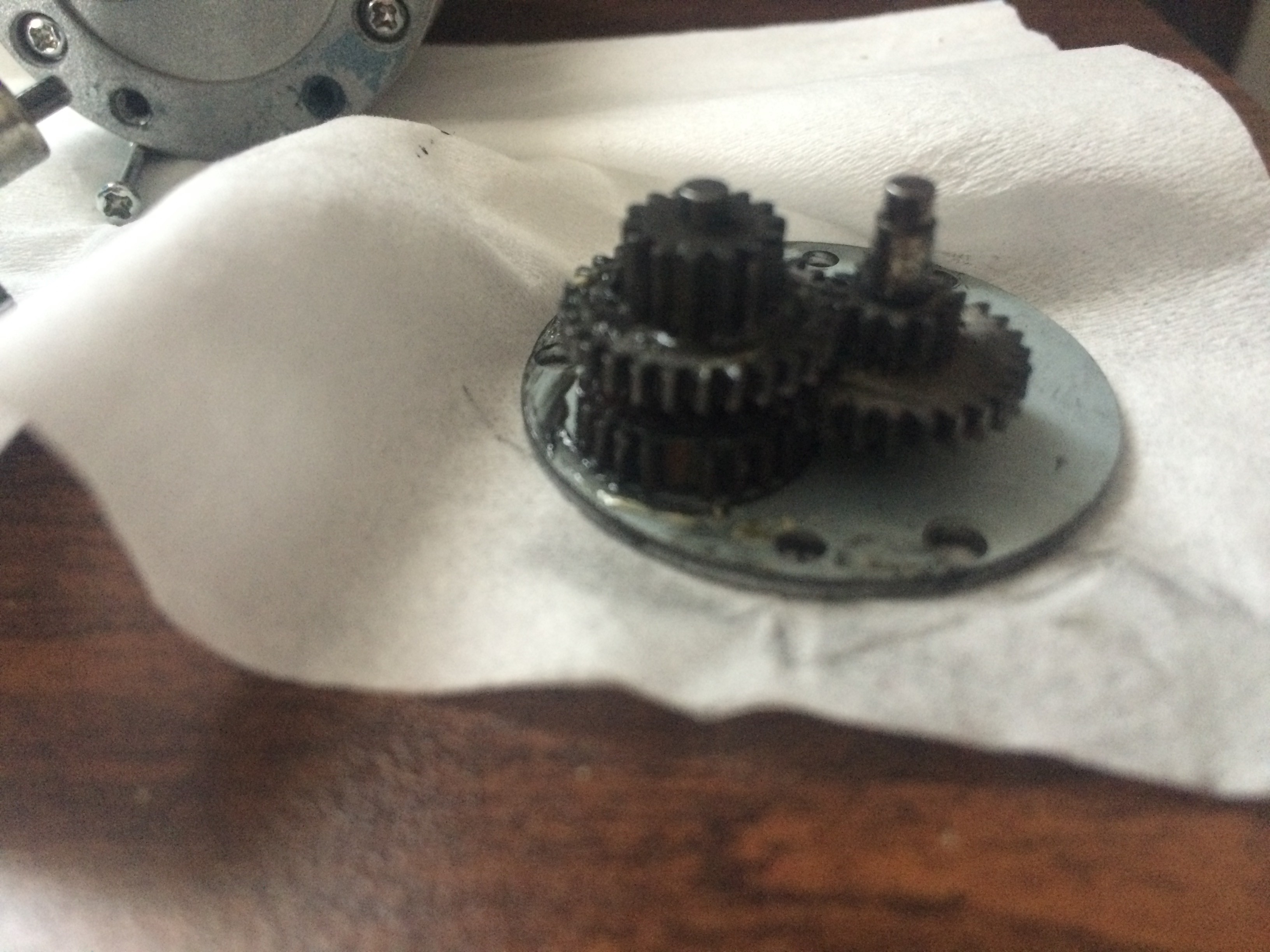
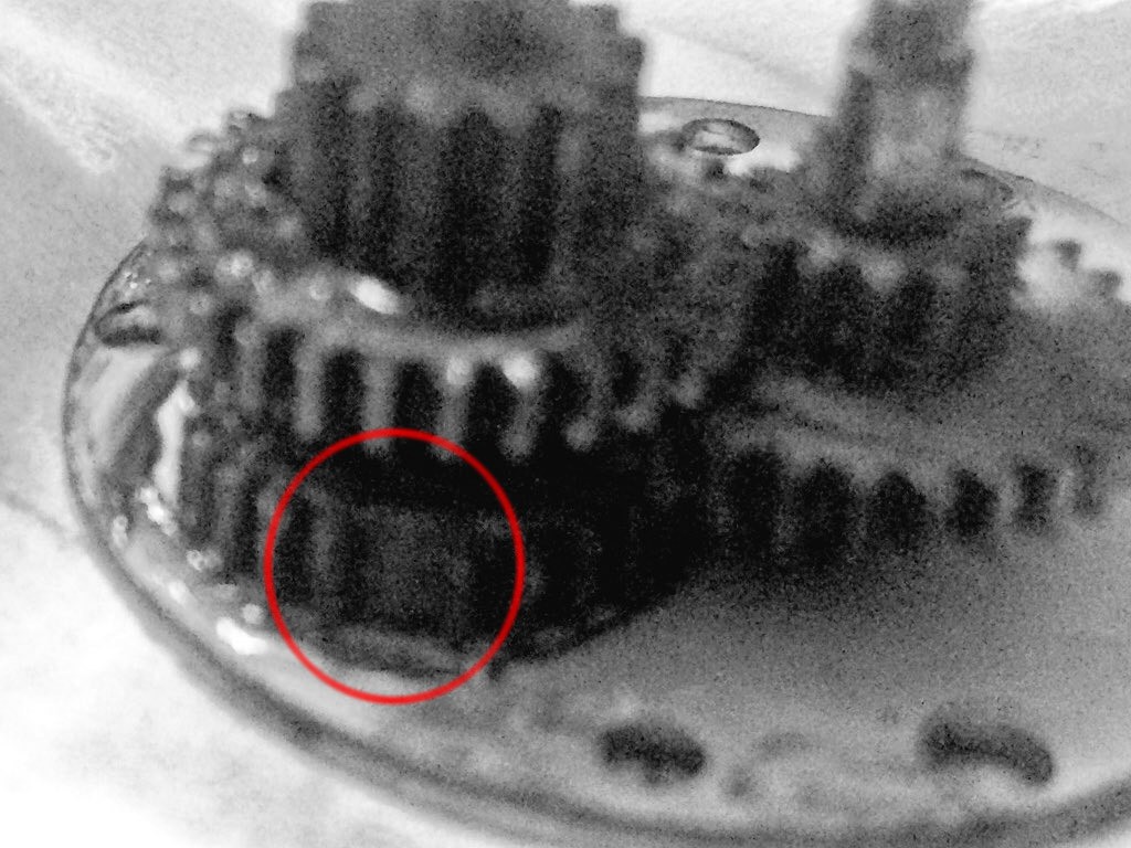
So when we were trundling down the long hallways in 2015, we impatiently pushed Bob along a little bit. Which definitely stressed the gears. Which lead to this terrible picture:
![]()
Do you see it? No?
![]()
There it is - one missing tooth. Crap.
Fortunately, I'd brought other motors with; I swapped back the 100:1 ratio that I'd used the year before, and we made it through the event. Slowly.
That, along with the list of the bits of the build that never got implemented in the first place, give me a good list of items to think about:
- Replace the motors with something faster and more reliable;
- Re-paint the gun stalk;
- Re-cast the collar;
- Live voice modulation, instead of pre-recorded pieces;
- Louder amplification (it's hard to hear in a noisy conference);
- Cleaned-up electronics (with better safeties);
- Painted-on black collar (the current one is a printed cut-out);
- Airway for sound to exit from the head;
- Replace the antenna (wire) that broke off of the Wii controller.
And probably a half dozen things I haven't thought about yet. :)
I'm sure I'm not going to get all that done for 2016.
-
Phase 3: The Electronics.
10/02/2016 at 13:56 • 0 commentsSo you saw a little bit of this in operation in Phase 2, where I tested the shoulder motors. Having never built a robot before, the motors were what I considered the most challenging part - I don't know what parts exist, what the problems might be, or how to even describe what I need. Other than to say "Bob weighs about 25 lbs. and I want him to move at about walking speed."
The general design: two motors and wheels in the base, near the back, which will drive the unit; two rolling balls in the front, so that I'm not dealing with the rotation of a caster wheel, defeating quick turns; two motors up top, rotating the shoulders. 12v, so I can run it from a motorcycle battery.
I picked a couple of motors pretty much at random off the Internet - a pair of 1:70 12v motors with ~80mm wheels. These were too fast for the shoulder and too slow for the main drive (also: not enough torque for the main drive, which was my first hint that this series of motors might barely be passable, but would probably never be good).
I don't have a lot of the build process documented, so let's do some retro-documentation here...
![]()
Obviously, you see several generations of work here. Originally there were no motors; I didn't know if I'd have time to finish them before LIWhoCon 2014. So there were three rolling balls and it was just a model, no remote control or electronics. All three were plastic (one is stainless steel in this shot - the spare, in the back).
But I did have the time. When I first went with motors, I mounted them in the front. That didn't work very well for reasons I don't remember, and I moved them to the back. The first set of motors I installed were too low powered, and I went with a pair of 100:1 ("37GB") 200rpm 12v motors that had enough torque - barely. And are too slow; probably somewhere under 2mph. (Math says: 80mm wheels and 200rpm = 1.86 mph.) So it's painful to walk alongside this while you're remote-controlling it from place to place. But it works.
The wheels have a rubber tire ring around a plastic wheel. The rubber stretched badly from the strain of moving this thing, and I abandoned rubber in favor of plasti-dip. Which wore off badly at the con in just a few hours. I wound up re-dipping them in our hotel room overnight. Now, they're covered in truck bed liner which is much, much better. (Thanks to someone at ProjectDalek for the hint on this one.)
The plastic wheels didn't fare well either. The plastic got badly chewed up, and I lost one ball in an elevator (used the spare!). In 2015 I wound up replacing them with steel balls that wouldn't get chewed up, but lost two of the three, and popped in the plastic replacements that I had with. I'm not sure any of these is sufficient, really, since I keep destroying and losing them.
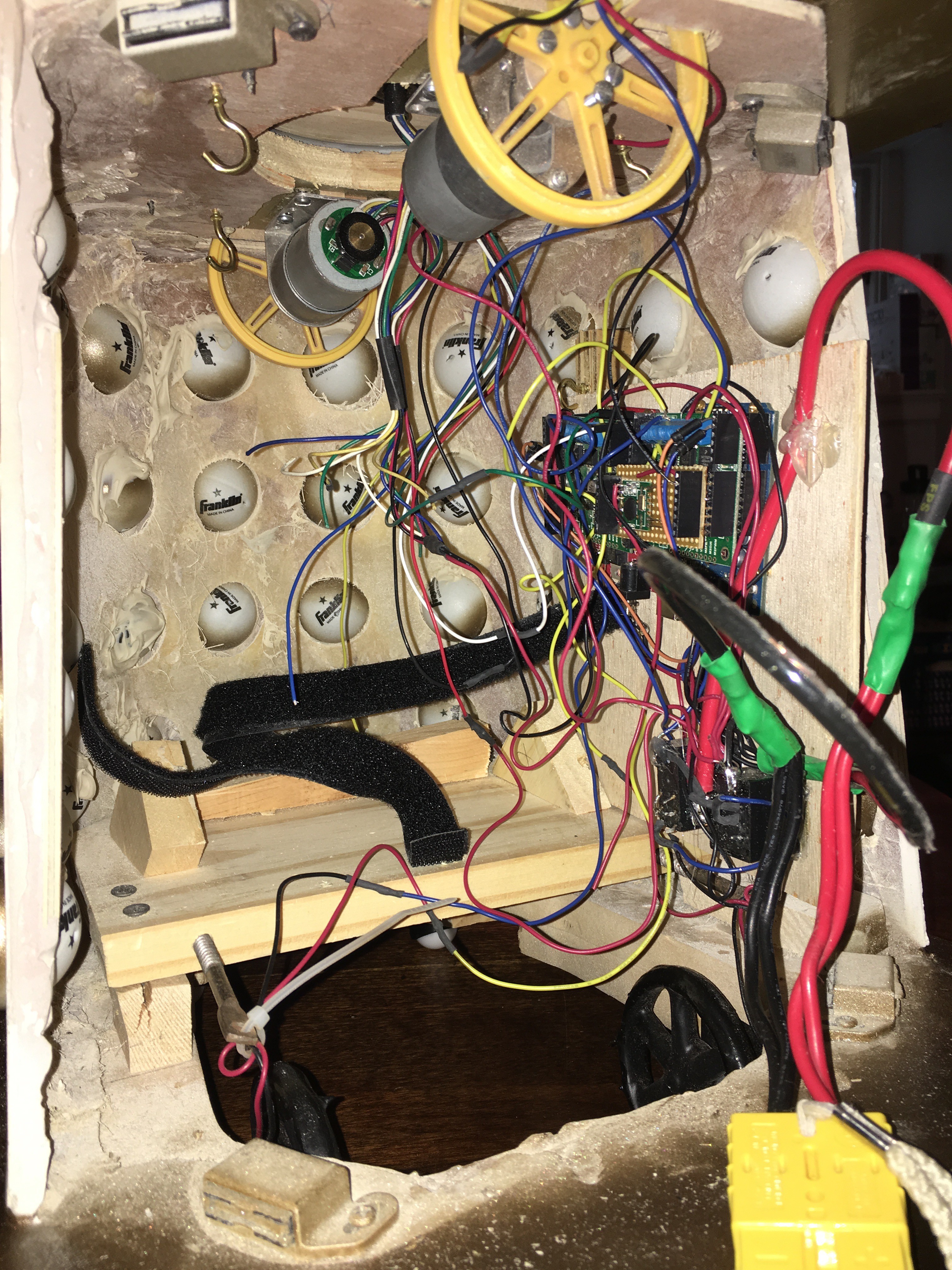
Here's the view on the inside, from the back hatch: the two yellow wheels on the top, and their motors, are driving the shoulder rotation. The force of gravity holding the top down (it's *really* heavy due to all of the bondo) is enough to keep good contact against the plastic of the wheels; no rubber (or rubberizing) required.
![]()
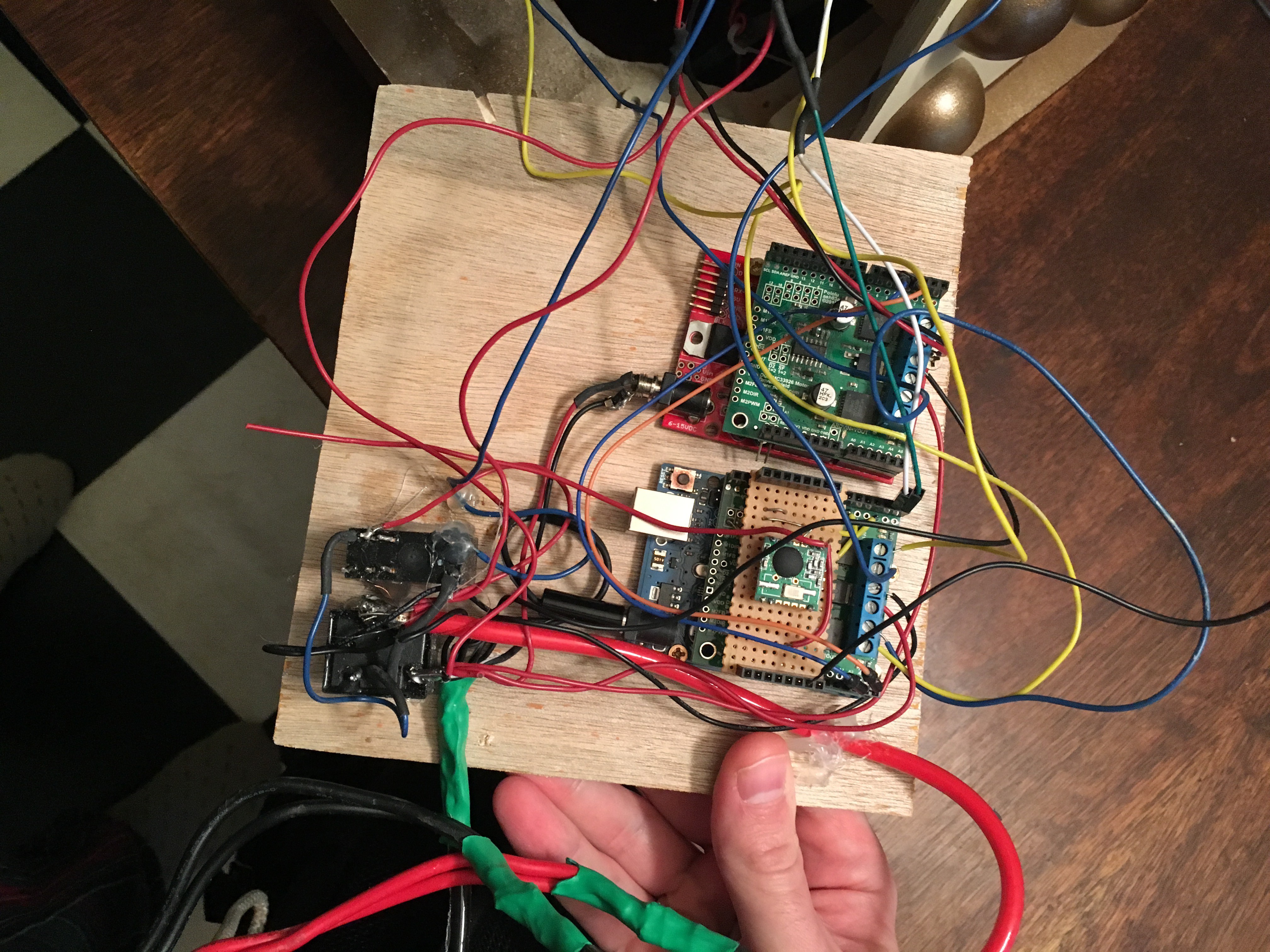
Here's the primary circuitry, mounted on a piece of luan that slides in next to the battery carrier.
![]()
The two things in the lower left are relays. One trips the other, for reasons I don't remember - but if I had to guess, it's because I wired it all up to one, and it didn't work properly, but the other one did, so I used one to trigger the other? If that's true I must have done it in the field. And I do remember that there was a stress fracture of something at the hotel the first year and I melted down some of the case of a relay to get enough metal exposed to reconnect it. So that's probably what happened.
This obviously could use some re-work. Which you'll hear more about later.
Then there are two arduino boards. The lower-right one is the master board. It does three things:
* RFM12B receiver (the protoboard on the top);
* Primary motor drive (terminal blocks just under it);
* Communication with the other boards in the unit (doling out commands that come in over RF).
The upper-right board drives the shoulder motors and nothing else.
There's also a third Arduino up in the head (connected through a 5A 6-wire conducting slip ring) that runs the audio with the help of a WAV shield and a CF card that has a bunch of audio files on it. You can also see a small amplifier in the upper-right, just before it connects to that speaker.
![]()
I want to say two things about my use of Arduinos here.
First: I used way too many of them because it was easy. Good engineering takes time. I didn't have time. I built a first-generation "it works, but not efficiently" system. This is, I firmly believe, good. It gives you the opportunity to understand the actual system requirements as you design, so that you can later design something that's better; it gets you a result fairly quickly, which lets you focus on the end-result instead of the intermediate details; it keeps you from prematurely optimizing something that's not actually a problem. There is nothing wrong with inefficiency and overkill in the first rev of anything. In subsequent revisions, you clean it up and make it more efficient. This is how successful engineering works on small scale, period.
Second: I prefer to hand-code assembly in PICs rather than using Arduinos and their IDE. But that takes time, and is more about crafting the code than about getting the result. I didn't have time for that here, so I fell back to the Arduinos for which libraries and hardware existed to do what I needed, on my timeline. The Arduino ecosystem is clearly an advantage for rapid prototyping, and I find myself using them a lot more than PICs these days.
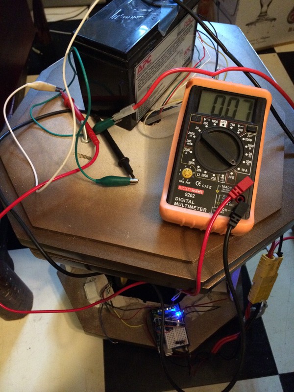
Once I had the bare bones together, I needed to understand the power requirements. I had no idea what the draw would be, and I was hoping to run it off of a motorcycle battery (because I had a few, scavenged from dead UPSes).
This was the first power test - 70mA draw quiescent (that's the arduinos), and about 3A full bore (that's the motors). Fine; I'll take a couple of batteries with me, and swap as necessary.
![]()
So with all of that looking fine, there's just the remote to build.
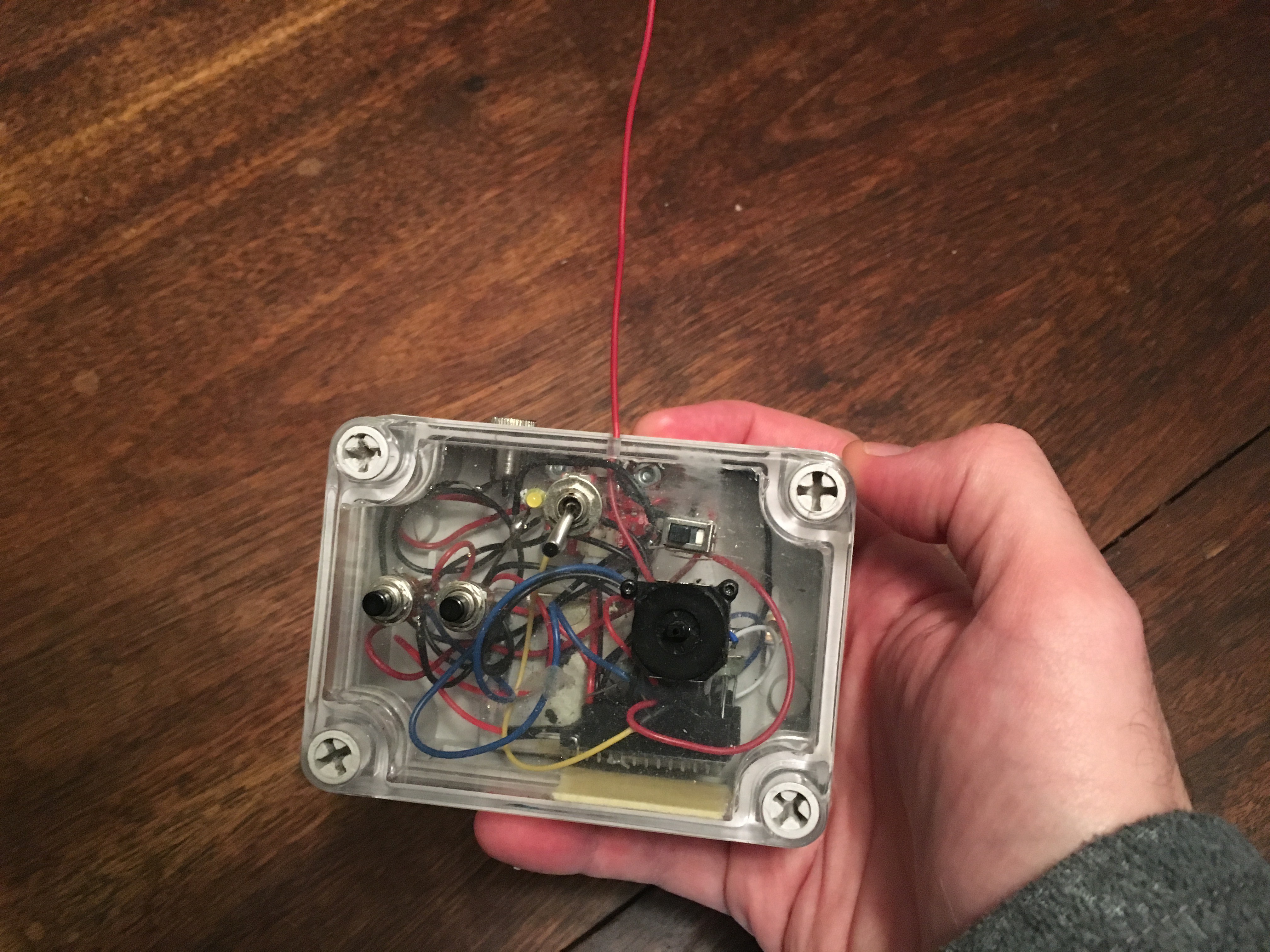
The first generation remote had two buttons to swivel the head, and a joystick to move the Dalek (vector math FTW). The long switch top-center is power, with a little power LED next to it, and the sliding switch to the right was to control whether Bob was in "slow" or "fast" mode. The whole thing is run by a Pro Mini 3v, and talks via RFM12B.
![]()
This remote worked reasonably well until we added the sound system. Now we needed to also select what kinds of sounds to play. And I realized that other people at the con would want to drive it around, and this is not exactly the most user-friendly remote.
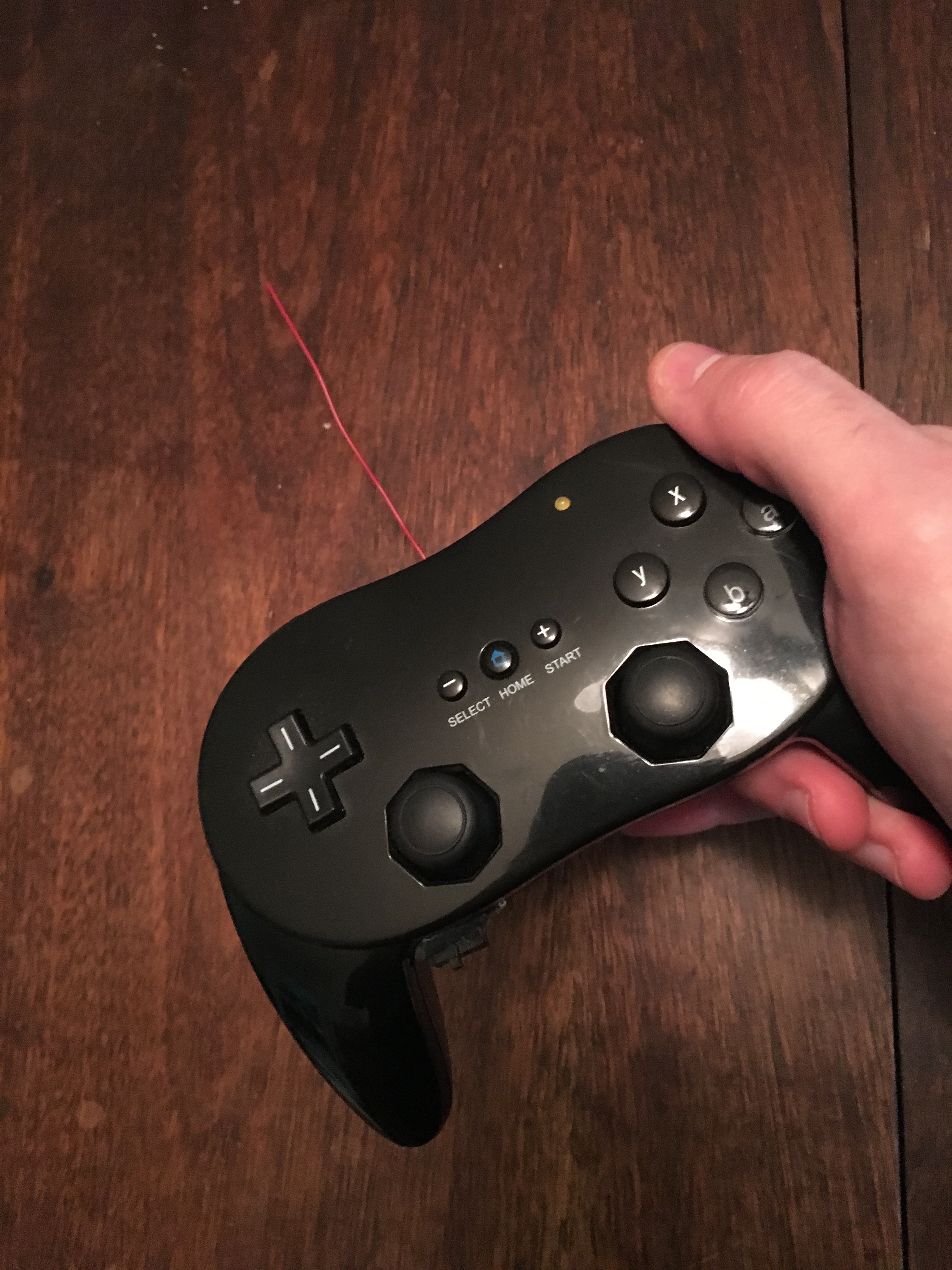
I spent some time thinking about what the right interface would be, and finally decided to build rev2 inside a generic Wii controller.
This was absolutely the right choice. We handed this to kids and they immediately figured out how to drive Bob. The right joystick controls the drive, while the left controls the head. Very intuitive. The rest of the buttons do things too (various sounds, slow and fast mode) but are a little less intuitive. I also added "hard brake" to ZL/ZR around the back, just in case. (With these motors? Not a chance!)![]()
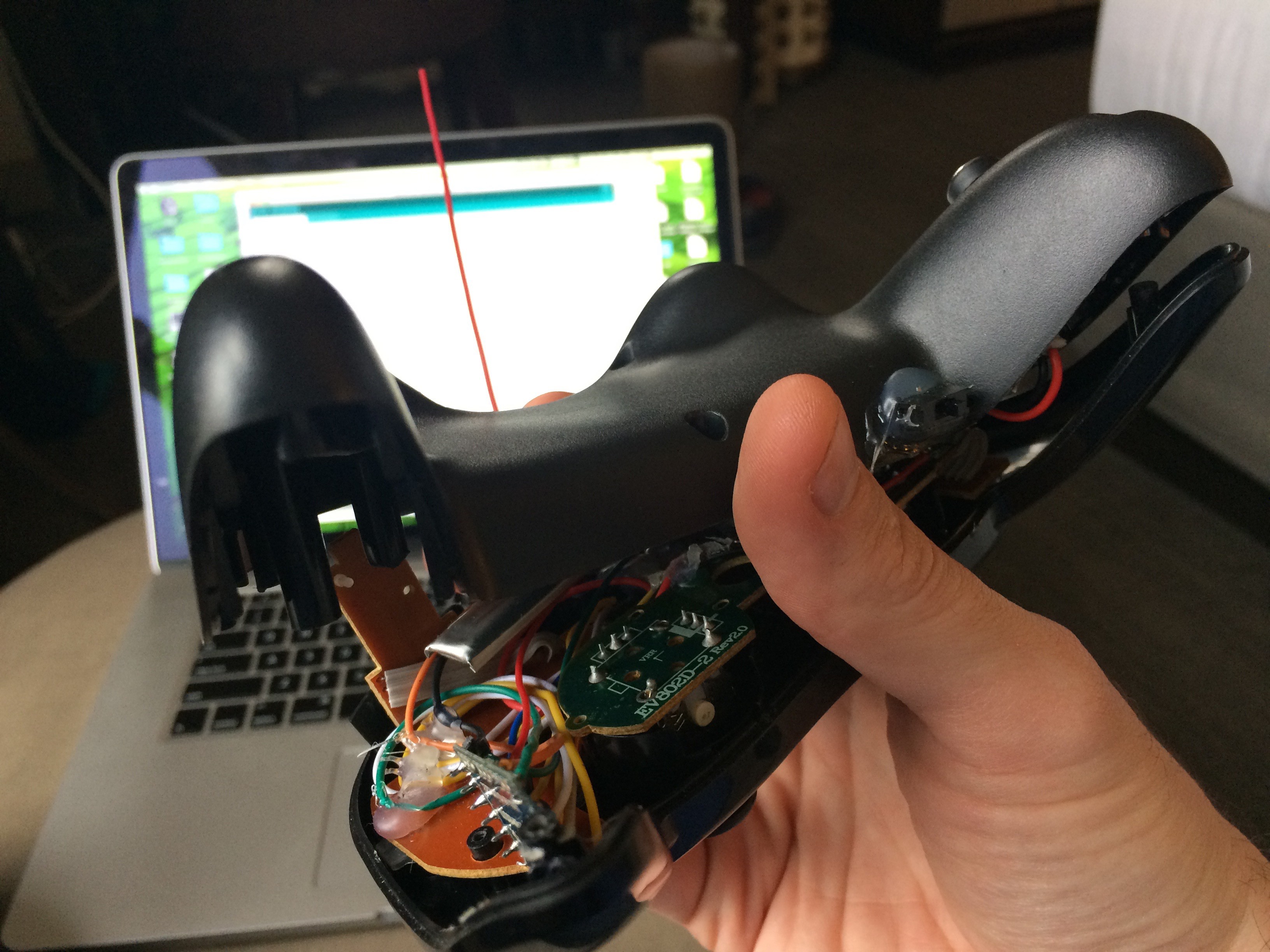
This is a tight build.
Here you can see the small silver (110mA) battery. Less obvious: the hard power switch (next to my thumb) and the Pro Mini embedded in it (which is edge-on, near the front of the picture).![]()
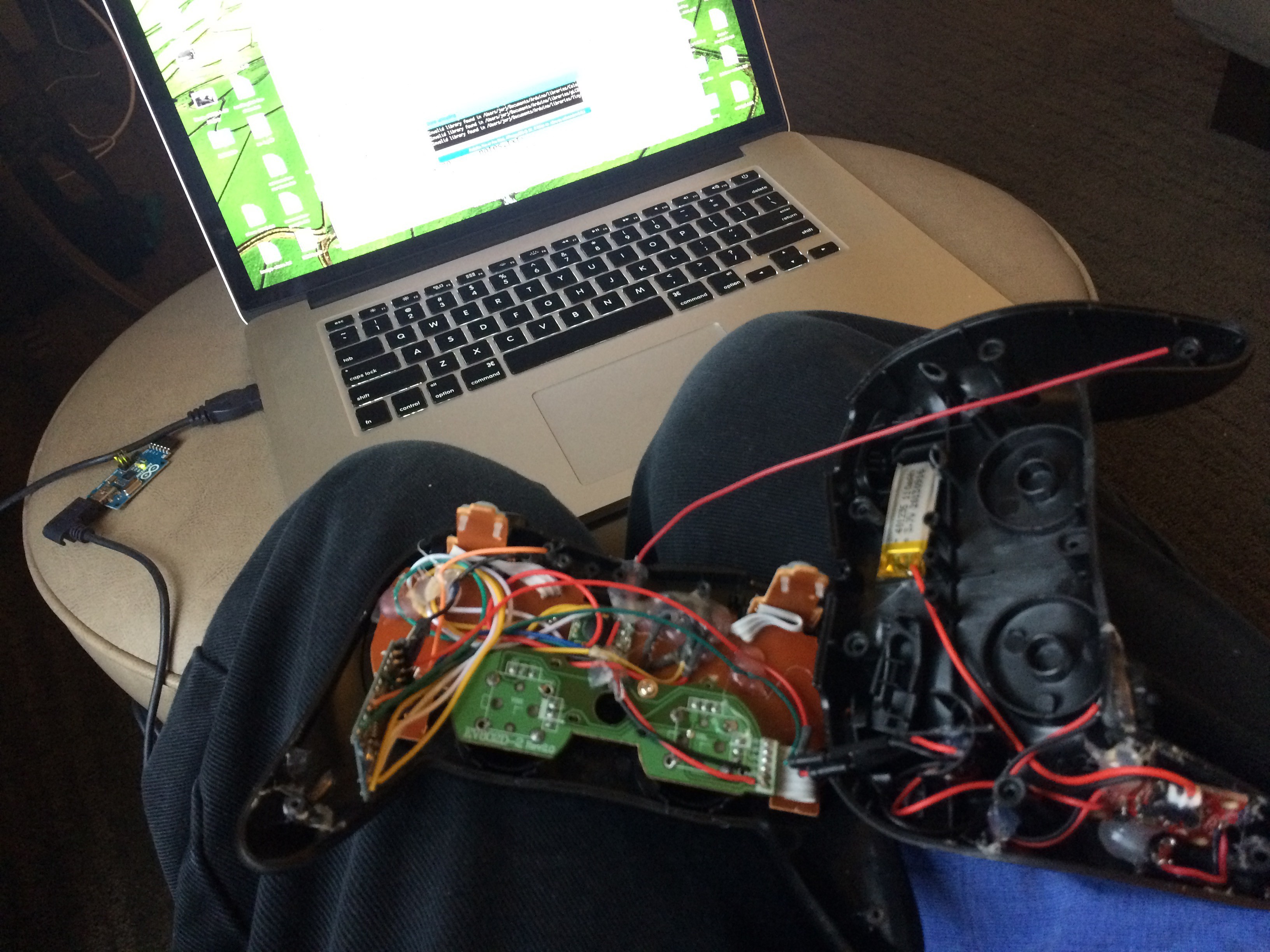
Somewhat more open, here it is again - the battery in the right, along with the charging circuit; and the pro mini in the lower-left:
![]()
So, does it work?
It's not ideal, but it functions! You can see that when it loses traction on the carpet, there's a lot of shaking because of how I'm driving the motors (trying to achieve the most efficient turn by driving one motor backward and the other forward). I eased up on the algorithm a bit to reduce the shaking after this test; not much else needed tweaking though.
-
Phase 2: The Model
10/01/2016 at 23:09 • 0 commentsI'd like to focus mostly on the electronics, so I'm going to zoom through the model build a bit.
The beginning of the model build was in November 2013. After assembling the outer shell and reinforcing it with some fiberglass on the inside, the weather quickly headed toward winter and the build stopped until August 2014, when we picked it up in earnest to complete by November 2014.
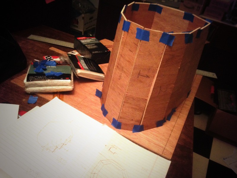
First up: rough cut Luan based on dimensions I worked out from templates, scaling, and a good amount of eyeballing.
![]()
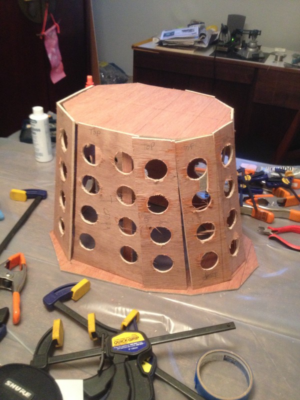
Mark and cut holes for the ping-pong balls.
![]()
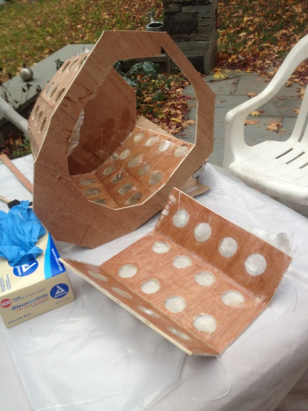
Glue in place with superglue and then fiberglass the inside.
![]()
![]()
I decided I'd build a hatch door in the back, instead of making the top removable, because I wanted to be able to pivot the head on the model and figured it would be easier to make the head a permanent fixture.
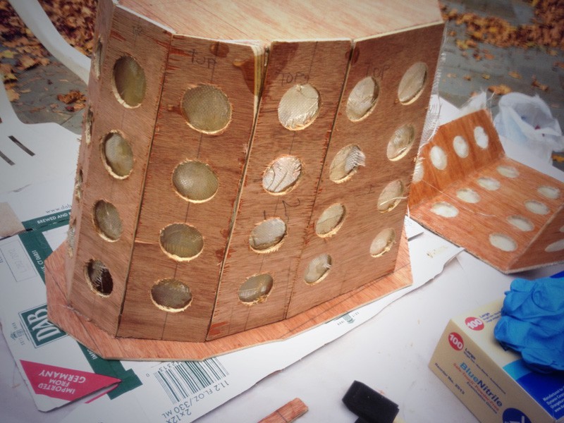
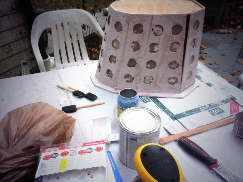
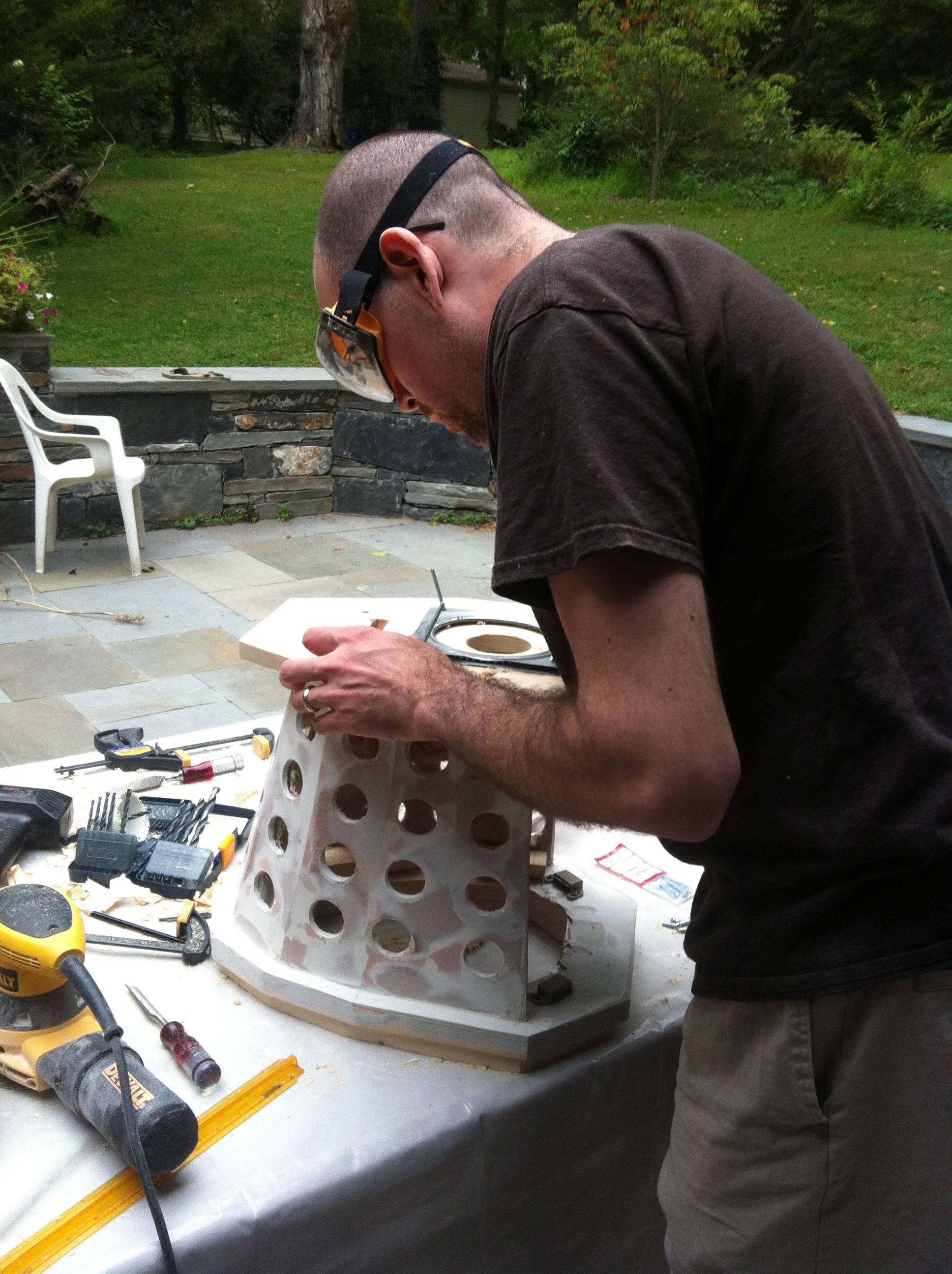
Next up: drywall compound to smooth out the front.
![]()
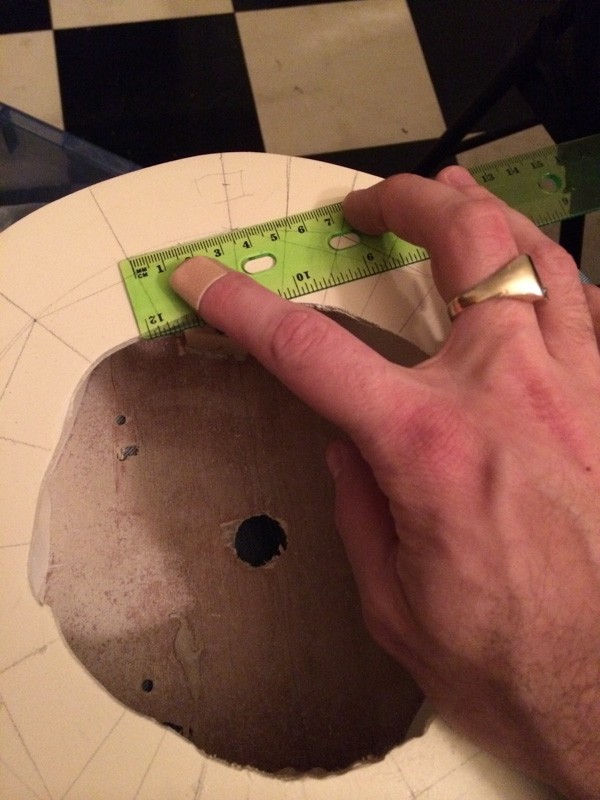
Sanding, re-measuring and marking the holes, and another pass with the hole saw. (In retrospect, it would have been better to drill all the holes much later in the build.)
![]()
Impatiently, I want to see what it looks like with some ping-pong balls of the right color...
![]()
... which means at least priming the base so it's a solid tone. This also made the flaws in the base very apparent.
![]()
Especially after rough-fitting the ping-pong balls.
![]()
I originally planned to cut the ping-pong balls in half; fill them with foam; and then mount them to the front without drilling holes. But that turned out to be difficult. I'd never tried to cut a ping-pong ball before, and let's just say that power tools generate too much heat; and xacto knives are too hard to get a straight line. Which is why I punted and drilled the holes instead. Which leaves these gaps around the balls, which I didn't want. So back to the drywall compound to fill around them:
![]()
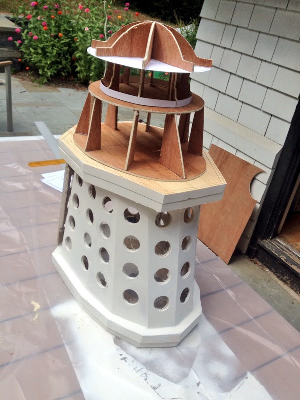
Also here, you see the first shoulders (which will rotate) and rough fit objects for scale and molding base (a lamp shade and can of mushrooms).
With the ping pong balls removed and the permanent pieces fixed together, we have a good idea of what the base will look like.
![]()
The four screws through the top are from the lazy susan between the two shoulder layers, which you can see me installing here...
![]()
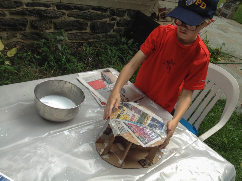
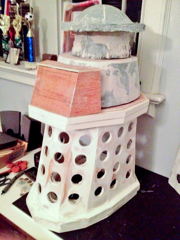
Next is the top. With some general guidance from the props above, I built a template out of cardboard with the intent of making a paper mache plug; making a mold; and then casting new pieces for the top out of fiberglass. Turns out I had no idea what the heck I was doing and this was a loss. But fun was had.
![]()
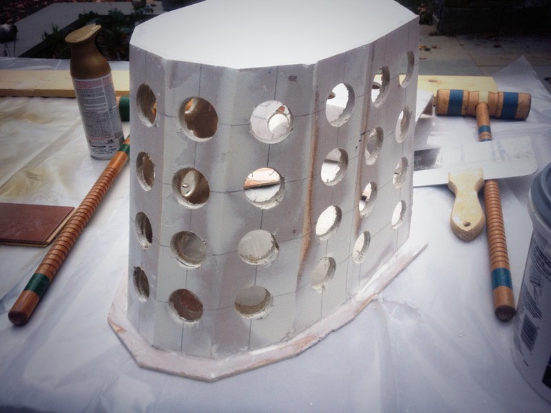
Reboot: new base forms made out of luan.
![]()
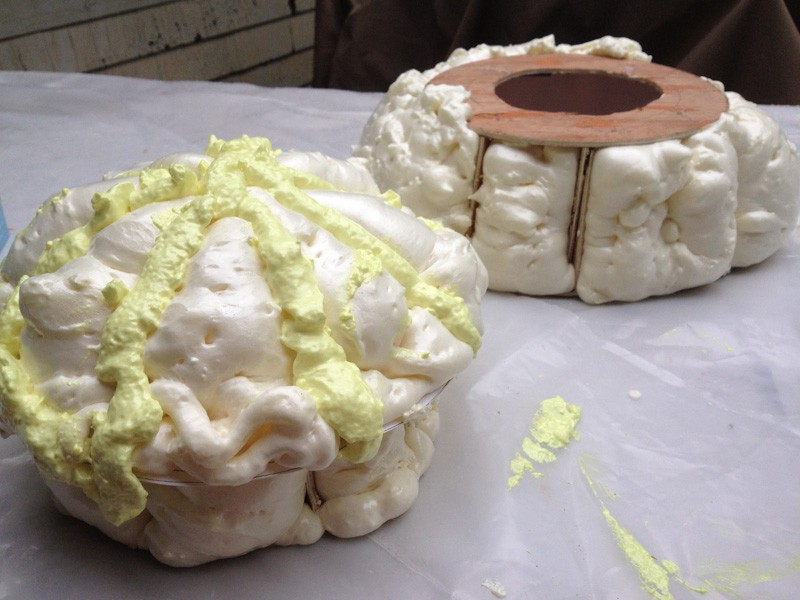
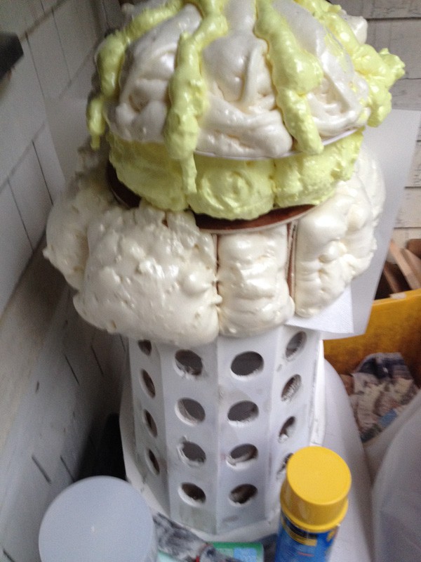
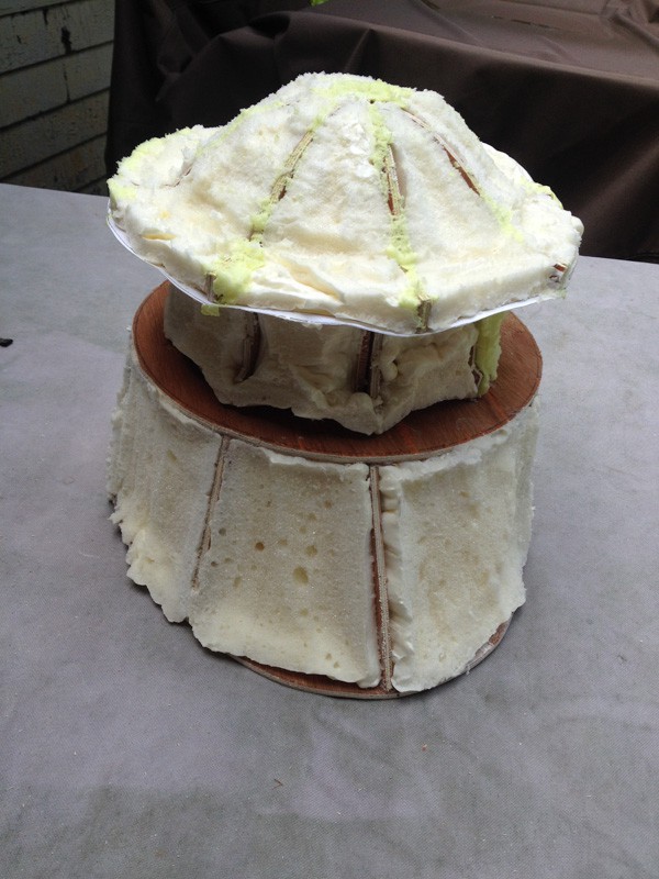
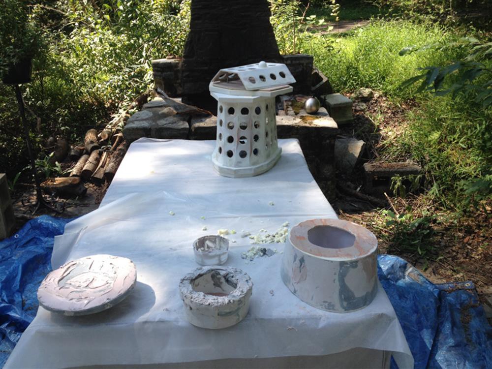
The idea is to fill them with expanding foam; trim it up; and then coat it with bondo to make a plug. About half way in to this I realize I don't have enough time to do that, so this is going to have to be the final piece itself.
![]()
![]()
![]()
![]()
![]()
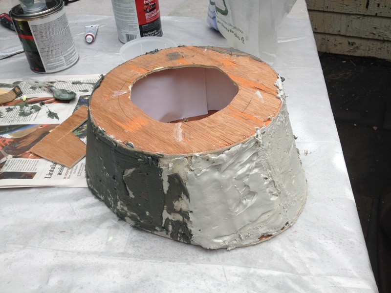
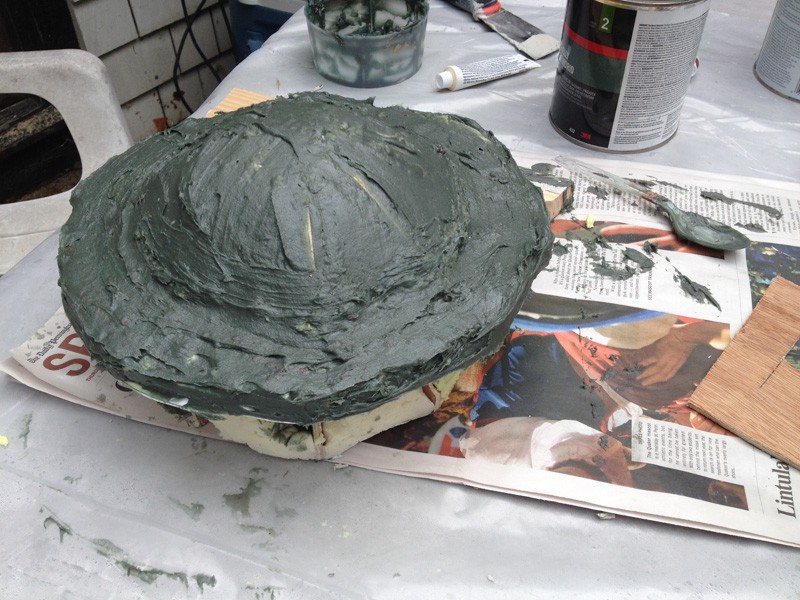
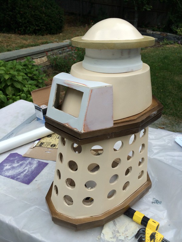
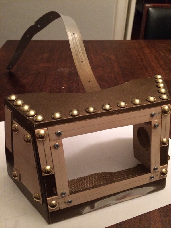
A little sanding and a rough cut of the gun box, and it's really taking shape.
![]()
The remaining pieces need a ton of work: sanding, filling, re-sanding, re-filling. Repeat times a billion. Seriously: at least a dozen. Maybe three dozen. I definitely lost count. So. Much. Sanding.
![]()
![]()
![]()
![]()
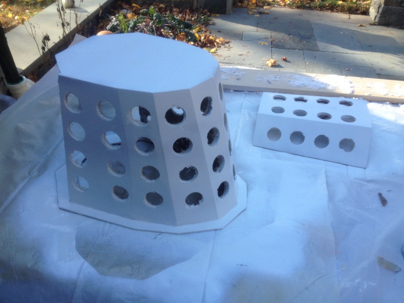
I had a real love-hate relationship with the white primer on this build. Think you're close to done? Spray it with some primer! OH MY GOD THE FLAWS. Nope, another round of filling and sanding. But eventually we get to finish coats...
![]()
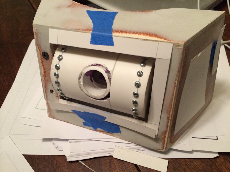
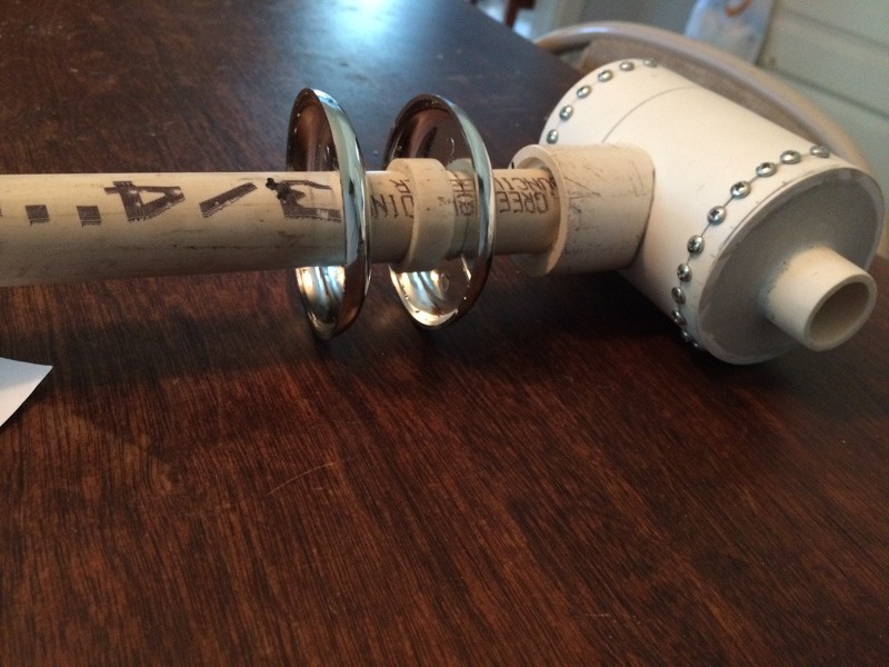
and it's time to build the gun out of miscellaneous parts from local hardware stores.
![]()
![]()
Before the final coat of paint on the gold shoulders, I did quite a bit of woodwork inside them that you can't see. I routed out a circle to hold a lazy susan, on which the top rotates; some holes for various wires; and there's a rotating wire collar that lets the wiring in the top stay untangled. I wanted the head to rotate a full 360 degrees. Perhaps not this quickly though.
![]()
Time to get down to brass tacks, literally...
![]()
Measuring for placement of said tacks.
![]()
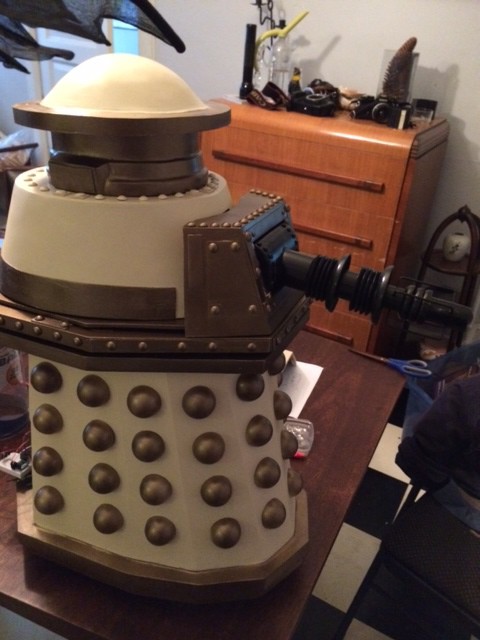
Some black spraypaint and automotive clear coat later, and the model is essentially done.
![]()
![]()
While that's not quite a final picture, it's close enough. Spot the flaws :)
-
Phase 1: research
10/01/2016 at 21:36 • 0 commentsIn the fall of 2013, my wife persuaded us (me and my then-8-year-old son) to head up to LIWhoCon - a Doctor Who convention on Long Island. We live just outside Philly so this seems like a hop skip and a jump.
My son had a great time - mostly hanging out in the games area - but he also listened to a few speakers. The highlight of his trip was hanging out with Sylvester McCoy, his favorite doctor. When we got home I suggested to j that we might build a dalek. And he had distinct ideas about which it should be - the Special Weapons Dalek, which had only had one on-screen appearance ever: with Sylvester McCoy.
Looking around the Internet, I found Project Dalek - a website devoted to Dalek modelers. They have fan-made plans from meticulous experimentation, on-screen measurement, and in-person visits to museum sets. While they're a subscription-based website, I was glad to pay them a few bucks a year to tap in to their knowledge base.
They didn't have any plans for the SWD, but neither did anyone else, really. There is a really low quality set of plans that were drawn by someone a decade ago, which give some rough measurements and are just about legible; but the base of the SWD is the same as the base of the Imperial Dalek, for which substantial drawings exist.
I figured these two sets of plans were sufficient to get me started.
We wanted this thing to be remote controlled, for maximum 9-year-old (and 40-some year old) fun. We needed to be able to transport it, us, and our luggage in our hatchback. I'd never built a robot, nor a movie prop - let alone one remote controlled and bigger than I am. So it was clear that we wouldn't be making a full-scale dalek. We wanted to actually complete something eventually. Hopefully within a year, so we could take it up to the next LIWho Con.
Now, having limited from-scratch manufacturing experience (except with wood, for reasons of furniture!), I looked at the plans and figured that the hemispheres on the Dalek were the most difficult part of the build. I don't have a vacuformer, nor interest in putting one in my already cramped basement. So I figured that if I could find a ready and cheap source for these, I'd be off to a good start. So, measuring some ping-pong balls and doing the math, I had my scale: at 40%, I could use ping-pong balls.
All of that planning took a couple of weeks; mostly scouring the internet for plans and then marrying them. So by mid-November we were ready to do *something*.