kelvinA
-
[M] Calculation updates and 15mm diameter?
9 hours ago • 0 commentsTetoroidiv-16 gets a Quick Stop force of 20.7mN, which should be enough to create virtual walls at speed. I've gone through all the 16mm brushless motor datasheets to find the constant that converts Kt to KV, and this is the data I have so far:
9.375 9.4125 9.425 9.4257 9.5625 9.5583 9.5468 9.5523 9.4572 9.4589 9.4674 9.4174 The average here is 9.47 which converts between mN.m to V/kRPM. To convert to V/RPM, the constant would be 9470.
Due to the existence of 5PH belt, which should be 8mm wide, and 15mm wide FSRs, I did look into the possibility of using 5PH317 along with a 15mm diameter motor that has a 46mm rotor length. This length was chosen so that I could potentially use 50mm wide SS-430 foil.
However, because those 15mm wide FSRs have a 10kg range instead of a 500g range (implying lower resolution for sensing forces from 0 - 300gf) and because of this paper finding out that key spacing down to 17mm does not seem to affect typing speed, but 16mm, I don't think there are suitable benefits to try for a 15mm x 150mm Tetrinsic.
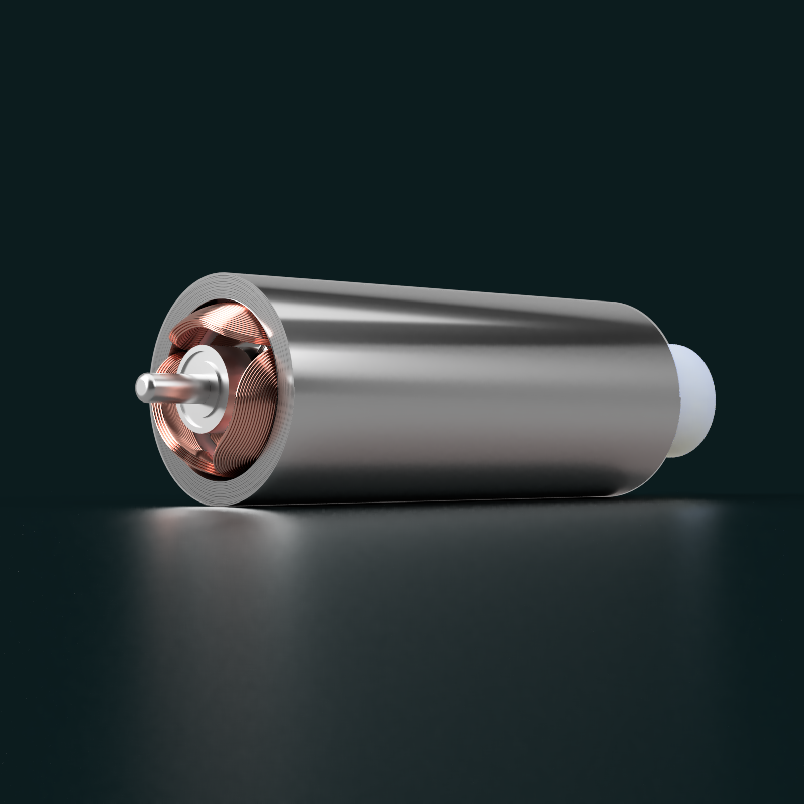
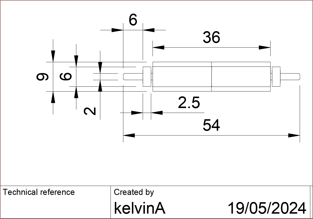
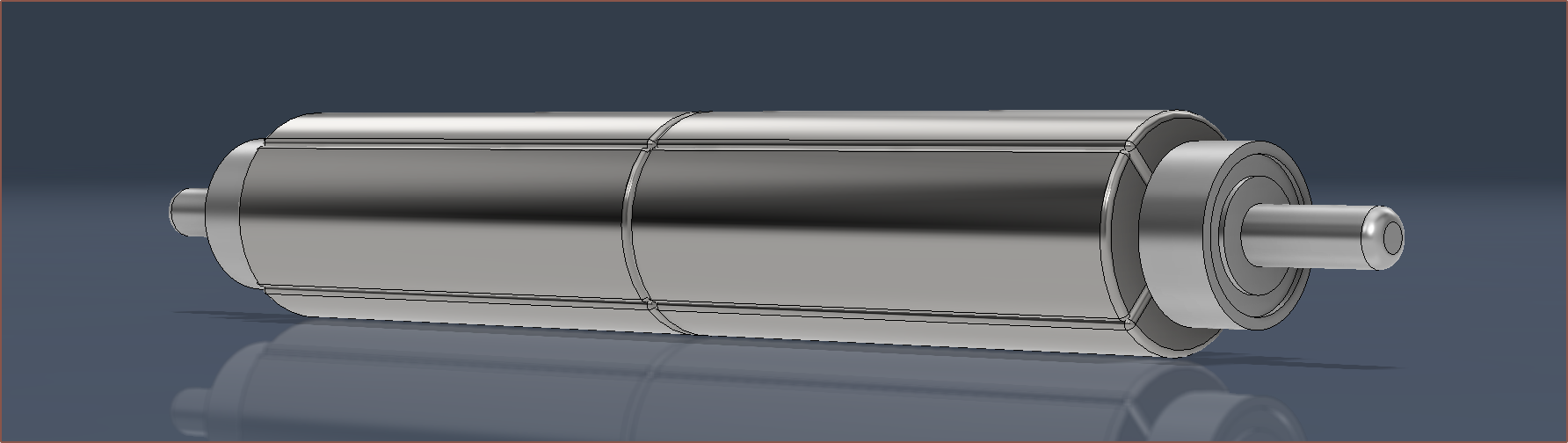
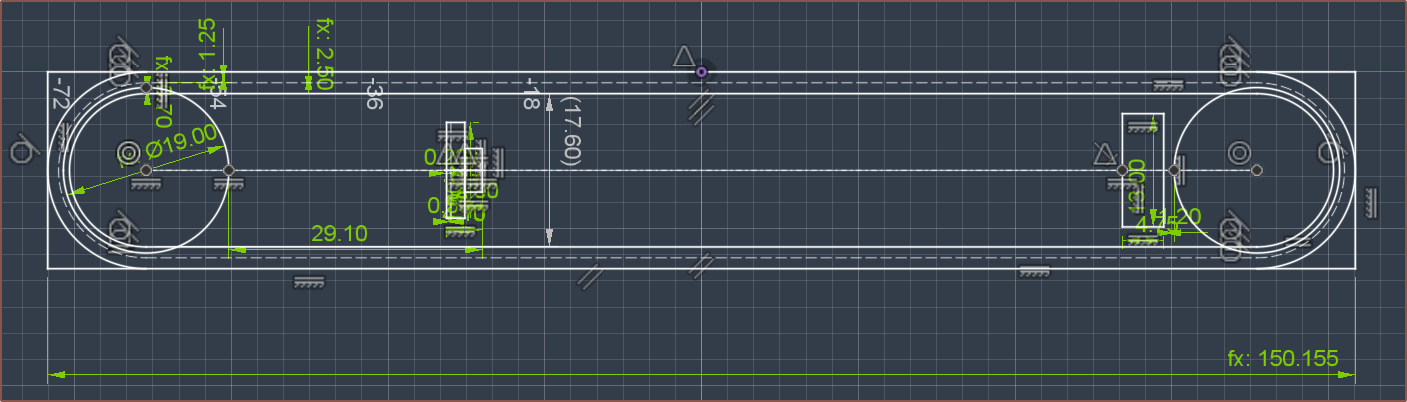
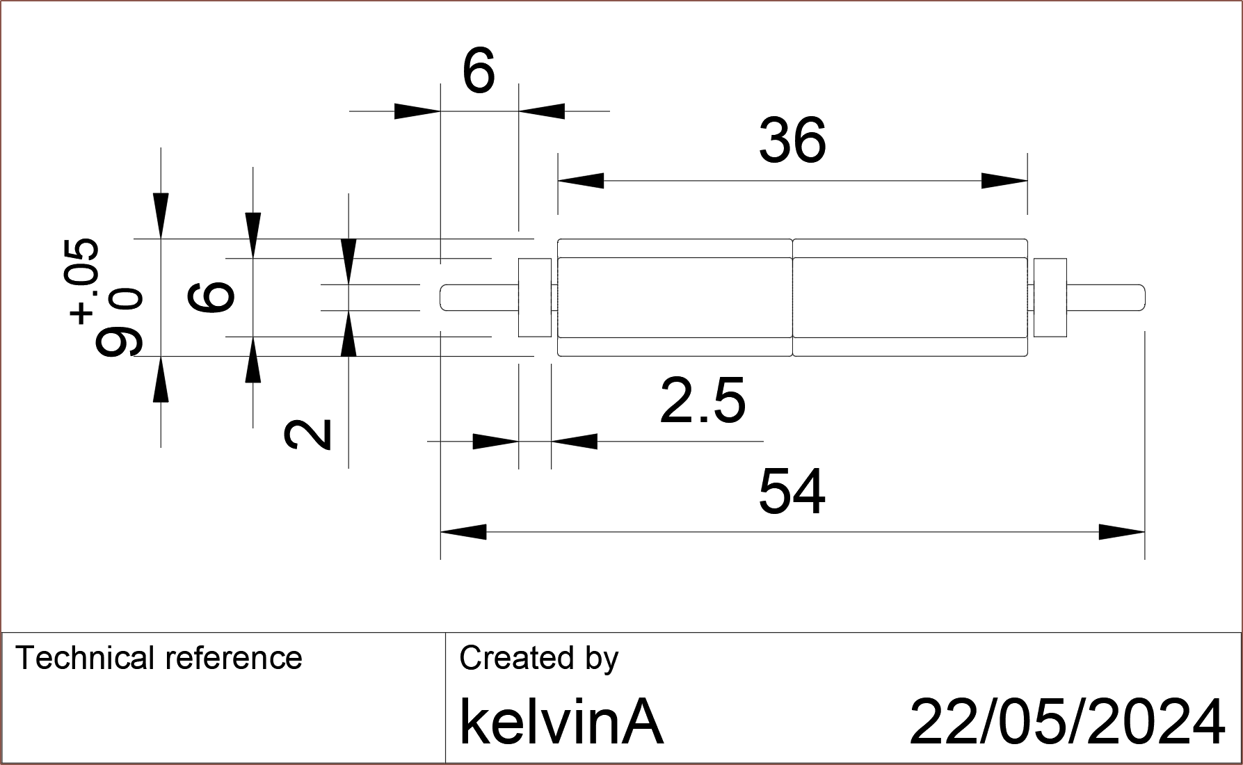
The following rotor design has seemed rather stable over these past few weeks so I've sent it to the rotor supplier:
I like how a few notable dimensions are divisible by 9. The rotor inertia is 1.65g.cm^2. -
[R] Microphone in a servo?
2 days ago • 0 commentsThe XIAO Sense boards manage to fit a microphone, and since I'm looking into ANC for Tetinerary, it makes some sense, especially since the Tetrinsics are planned to be infront of the ear.
I wasn't able to find anything decent for a decent price on JLC's part library, but I have found 2 sub-£1 options on Digikey that have the full 20 - 20,000Hz of range and relatively high SNR ratios along side a -26dB sensitivity. According to the Infineon datasheet, this allows capturing the full dynamic range with 16-bit PDM, which is the max the nRF52833 supports. Coincidentally, the 833 samples at 16kHz, just like the proposed speed of the Field Orientation Control loop.
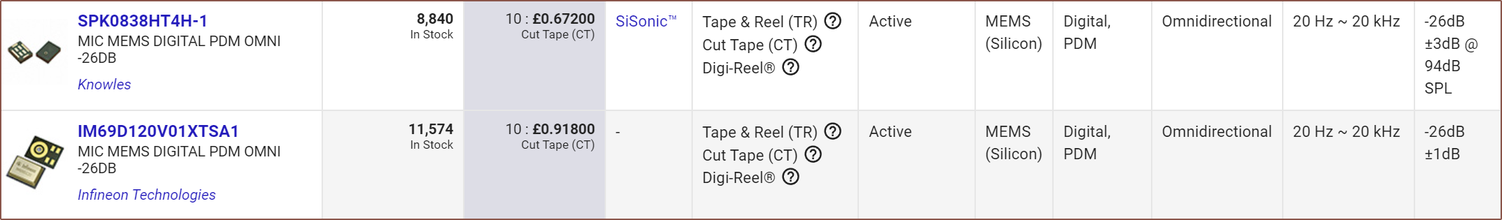
Digikey's XENSIV page was the first thing I found on my search and the IM69D120 does seem like the best option, with a 69dB SNR.
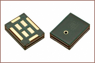
The SPK0838HT4H is cheaper and has a 64dB SNR, which seems more typical as most others I've seen are 60, 63 and 64dB. It also has the mic port on the top instead of the bottom, and unlike most, doesn't seem to have a shield and seems to be made out of PCB:
There's also the IM70D122 which has a similar but not identical footprint and has IP57 water resistance.
These microphones need 3 pins, meaning that the PCB would need 19 / 20 available GPIOs.
-
[E1][X][M] Peak speed problems avoided
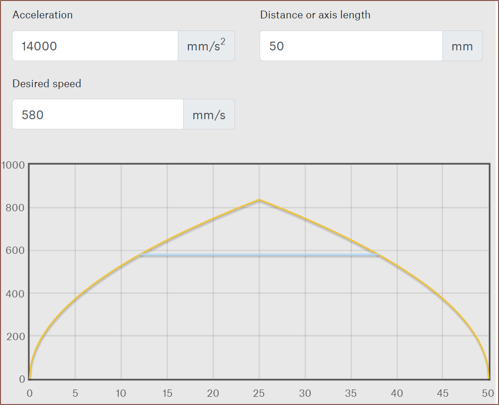
05/20/2024 at 09:21 • 0 commentsSo I had the idea to actually create a simple PowerPoint animation where the orange bar would slide up and down 50mm with a smooth start/end transition to account for acceleration. Then, the time duration of both the animation and the transition to the next slide would be changed so that it looks like my finger is actually moving the slider. I found that a 0.12s animation and 0.14s slide transition achieved this without my finger doing any particular effort.
Then I finally used the SUVAT equations in the real world for once and I got an accel value of 13.89m/s^2. Since all these measurements are kind of rough, I stuck with 2 significant figures thoughout, thus I used 14m/s^2 for my calculations.
I then used Prusa's calculator to graph out the speed profile when doing the expected max typical movement of 24mm (each column in the Tetent layout is 6mm apart):
I confirmed that it was 580mm/s. If you're wondering, the peak finger movement from end-to-end was 833mm/s.
Dividing this by the circumference of the 16mm pulley, converting to RPM and then multiplying by the gear ratio and I got 5000RPM to 2sf.
This is a bit of a problem because I still need to be able to generate a virtual wall force at these speeds, such as if the finger starts to accelerate and then hits the virual wall halfway through the movement.
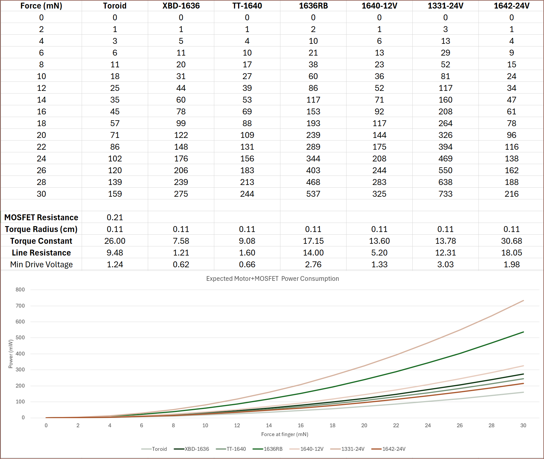
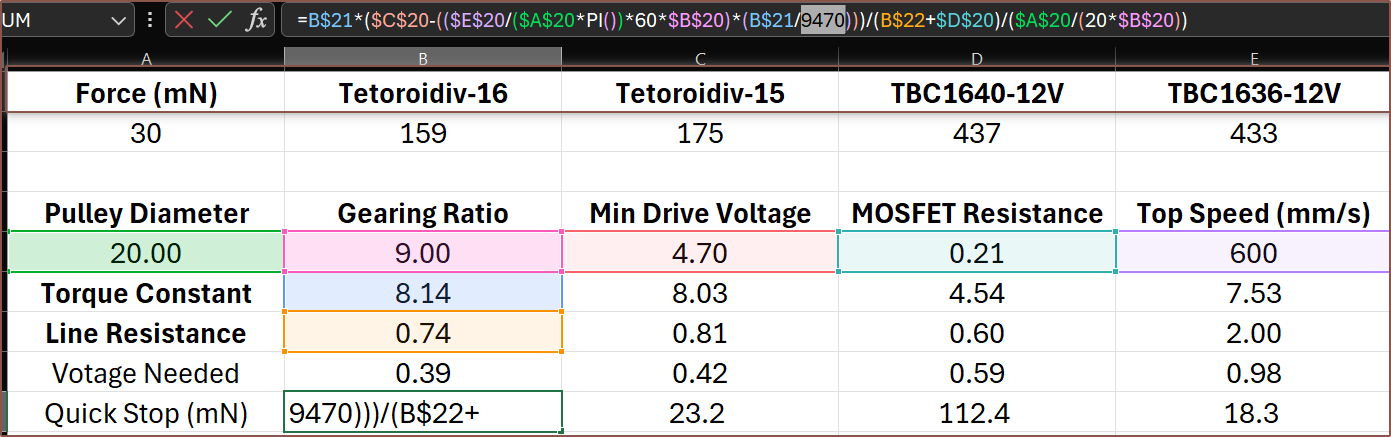
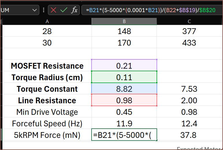
After spending a while deriving the correct equation, it's not looking good at 5KRPM:
The equation used. A more complete equation is further down in the log. First row is rotations per second whilst still providing 30mN and the second row is the force applicable to the belt at 5kRPM if positive. Understandably, negative values all coincide with all motors with a torque constant over 10. For example, I needed to go to the TBC1636-12V to get a non-negative force of 37.8mN and that configuration uses 44% more power than the 24V variant.
Finding the max turn count
10 > 13.77x / 38
380/13.77 > x
27.6 > x
Turns need to be 27 or less.
I did also consider just having a higher drive voltage that would sidestep all of this, such as running the motor at 9V, but that may complicate electrical matters (not like running a motor on the same 5V rail as logic circuitry is a smooth sailing idea either) since it would be nice to have everything fully contained on Tetoroidiv.
Actually, as I'm typing this, I'm checking motors to make sure everything is all correct, and it's not. For starters, a 1656 motor snuck into the data. Additionally, assuming 0 voltage drop on the 5V rail is likely inaccurate. All this happened way past when I usually go to sleep because, as they say, "I don't need sleep, I need solutions!"
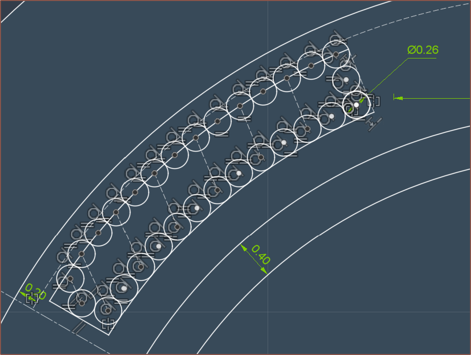
Anyway, 0.25mm wasn't going to make it, and since I can only have discrete coil heights, it meant that I started looking at the 0.3 / 0.35 / 0.4mm wire options. I was going to write this log talking about how power consumption has gone up 180mW just so that I could get a configuration that still had torque at 5kRPM, but I guess the sleep assisted because I've just tried a 0.35mm 21T option:
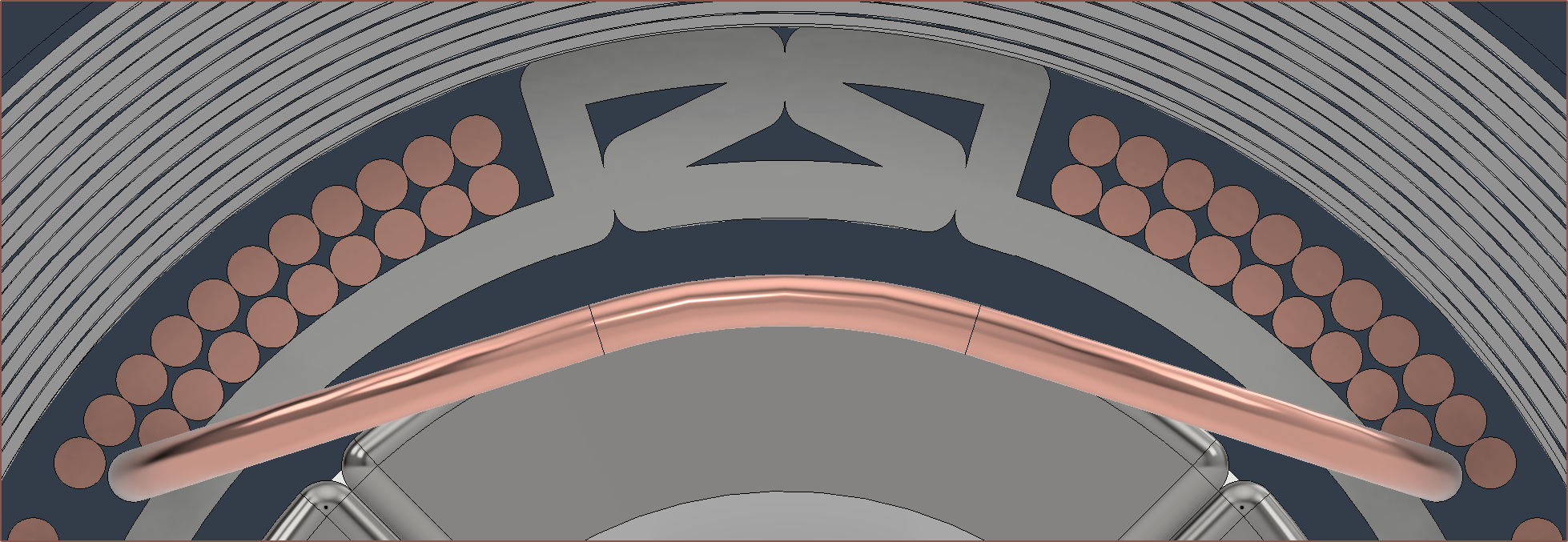
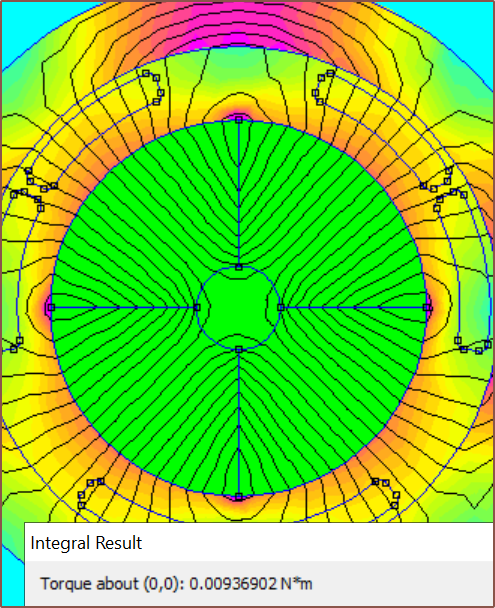
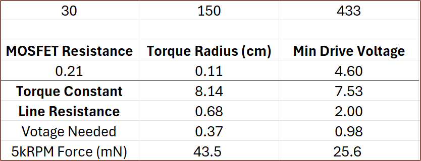
For 0.3mm and above, there are only 2 rows of wire CSAs, meaning that I don't need to extrapolate how many turns will fit. Simulation with 9mm rotor and 21 turns, and the other magnet oriented to maximise the KV of the motor. Toroidiv against the TBC1636-12V 110mW is the all-time lowest power consumption I've witnessed. Considering my fingers would likely be in (what the enthusiast 3D printing group calls) "sensorless homing mode", 6.4mN should be enough to set a speed limit and decelerate my finger enough to reduce the EMF enough so that the motor can apply the full torque. I'm not going to risk it though and would rather use 20 turns; the max power goes up by 6mW but the max force on the belt goes to 25.5mN at 5kRPM.
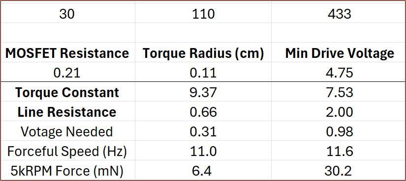
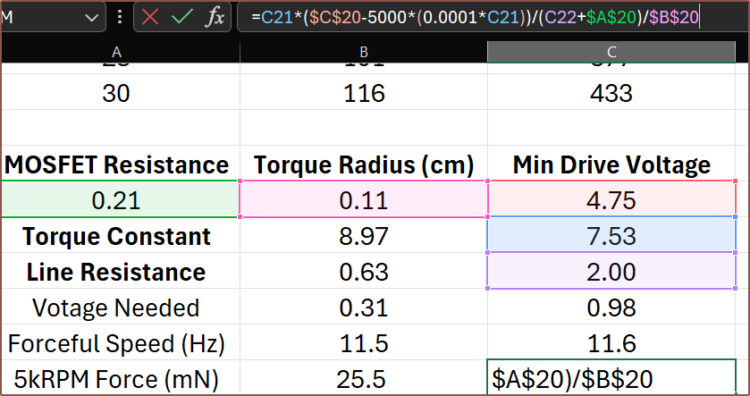
A more complete equation to calculate the force exerted on the belt. It calculates the back-EMF at 5kRPM, which is subtracted by the minimum drive voltage. This is then divided by the total resistance to obtain the current. Next, this current is multiplied by the torque constant to obtain the torque generated by the motor. Finally, this is divided by the torque radius to get the force on the belt. I believe that a 580mm/s speed limit would probably go unnoticed:
The finger should spend about 45 milliseconds at that max speed. This is about 1/3rd of the entire motion time, with the acceleration / deceleration taking 41ms. In total, it's 127ms. I checked all configurations of the brushed 1640 and none can provide torque at 5kRPM, meaning that the 1742 is the only brushed option at the moment. Currently, none of the commercial options are even close to the custom-designed solution, with the explanation for the BLDC options likely being because they only have a single pole pair.
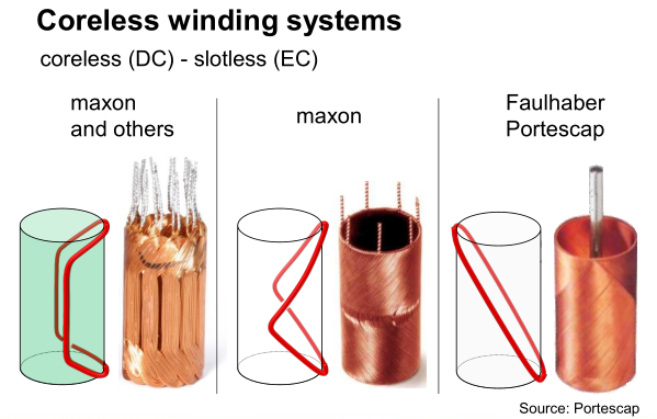
Green is brushless and copper is brushed. Another explanation is because these motors are usually made with windings such that they're self supporting, but it means that the wires themselves usually don't run perpendicular to the movement of the permanent magnetic field thus only a component of the total actually creates torque:
It's still more likely to be the pole pairs though. For example, if the TBC1636 had 2pp instead of 1, the power consumption would theoretically be 108mW.
[May 21]
I found out that the simulation is somewhat unreliable, in that changing the spacing between coils by tiny amounts would affect the torque integration substantially. For example, I'd get 6.76, 7.37 and 5.3 for 3.8mm, 3.6mm and 3.4mm respectively. It did seem though that values typically decreased on either side of 3.6mm.
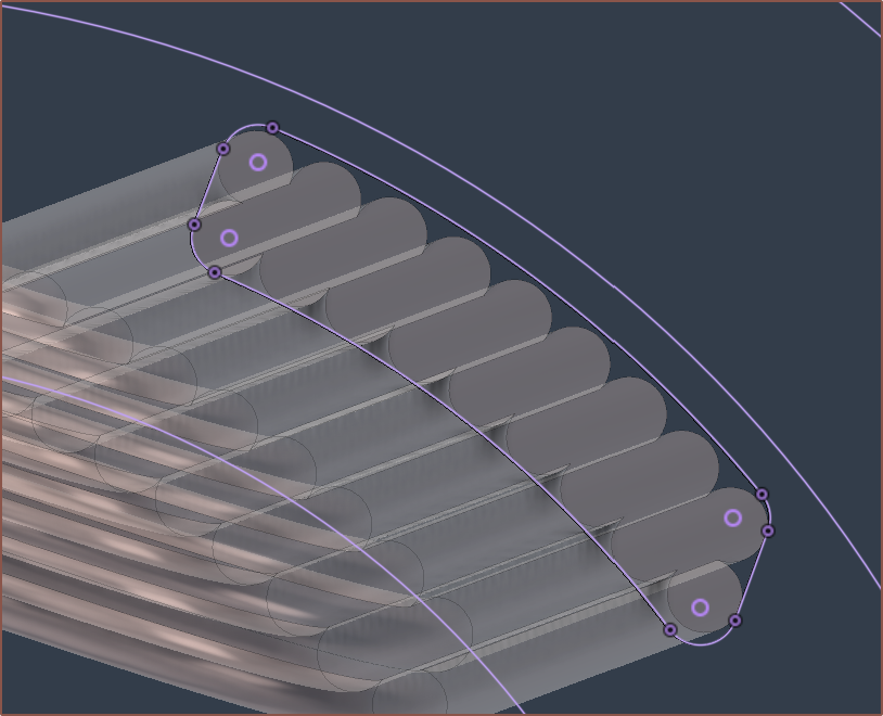
I tried things like modelling with a more accurate CSA (see below), and got 9.7 for 19 turns but 2.3 for 18 turns, so there was certainly something mysterious going on.
So then I tried an ultra-simplified CSA, where I got 6.8 and 4.9 for 3.6mm and 3.61mm respectively. The stars aligned when I used
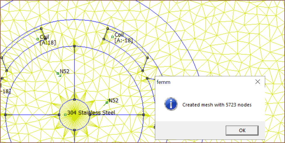
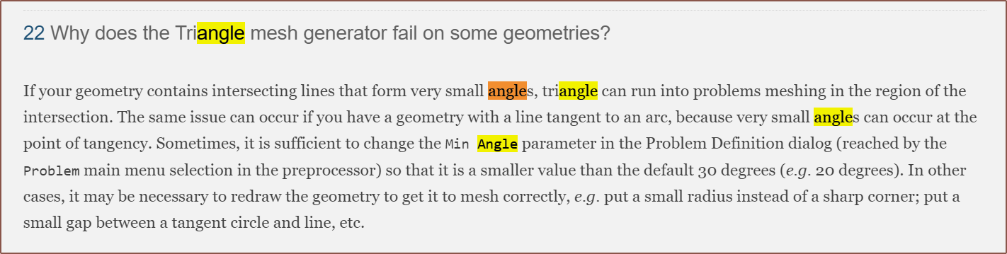
This is spacing of 3.61mm I looked into my problem settings and started tweaking values to see if anything made a difference, and min angle certainly did:
Minimum Angle = 1 Minimum Angle = 30 So I looked it up and this is what I found:
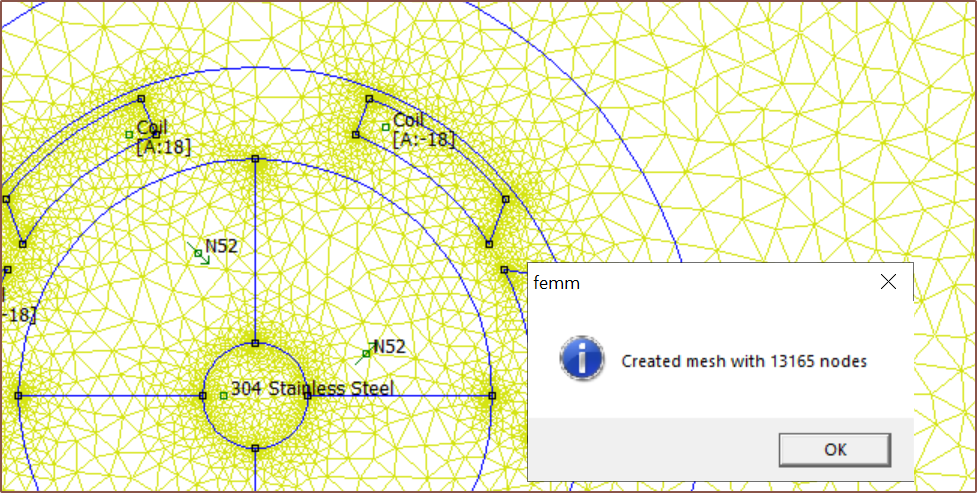
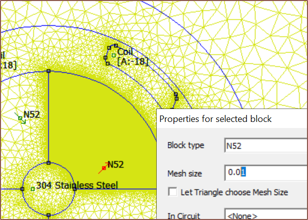
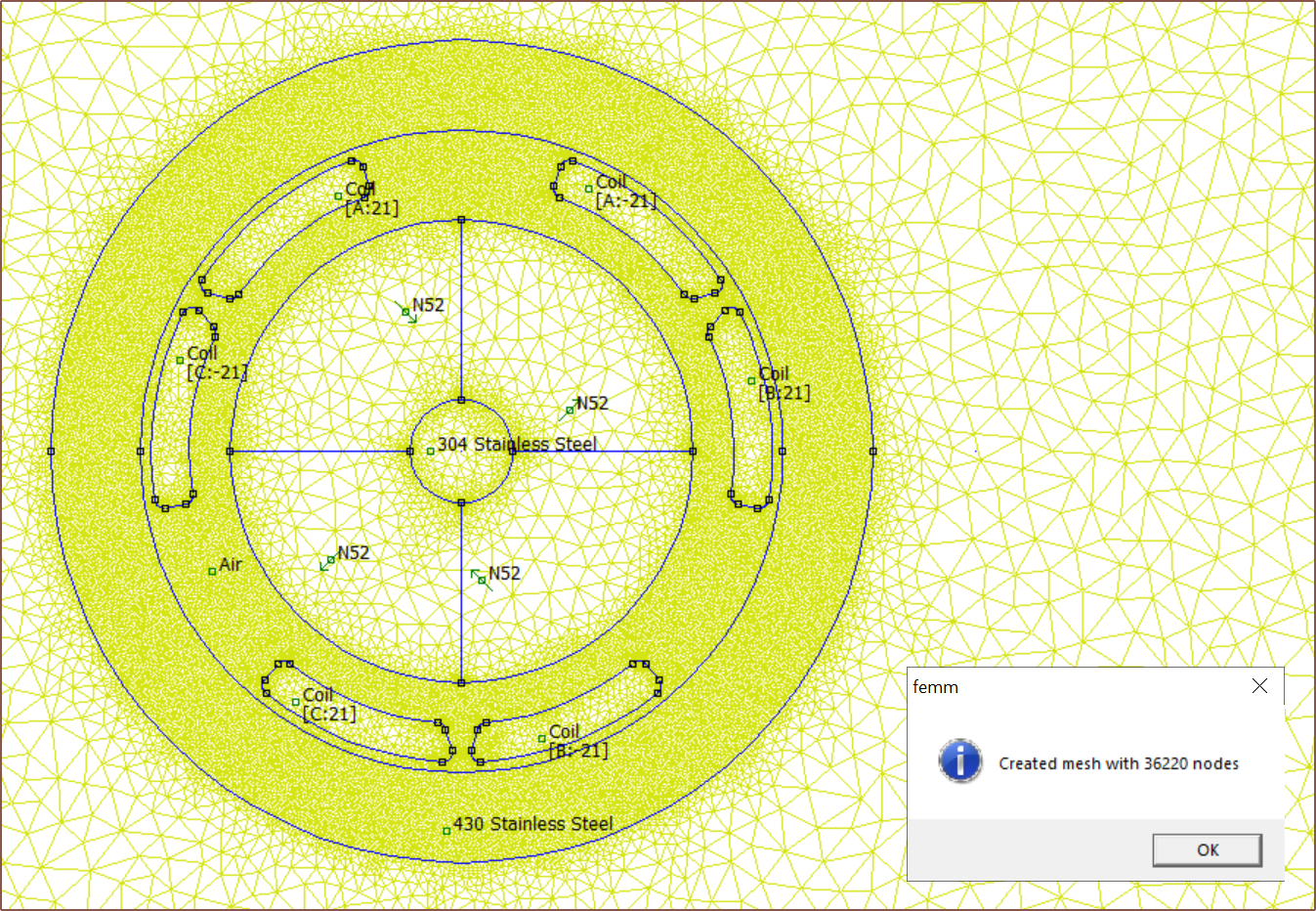
That might explain why the BLDC tutorial dropped the min angle to 20, which is what I had it set as. Thus, I went back to a rounded-edge CSA and started trying out different mesh settings for the air (inside the motor) and yoke, and I found that a mesh size of under 0.1 gave results that were reliable enough (+/- 0.1 torque constant).
Rounded edge CSA. I misread the "line tangent to an arc" part because of the "put a small radius instead of a sharp corner", but it seems fine enough. Experimenting to see if larger or smaller sizes get a finer mesh. Mesh size of 0.08 for the air and SS-430. I also learned that I didn't have to generate the mesh before solving, as FEMM does that automatically. That means that I don't have to deal with the performance penalty of displaying so many nodes. Alternatively, I could always toggle "Mesh -> Show Mesh" in the top bar.
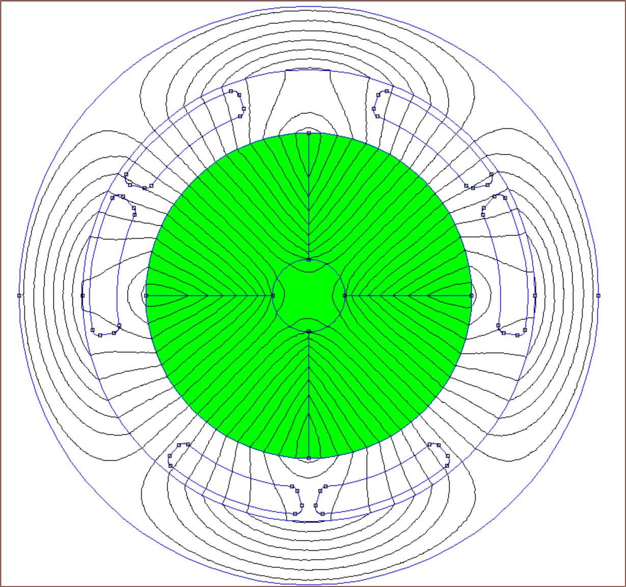
The solve takes maybe an extra 5 seconds but the flux lines look much smoother and, as mentioned before, the result is more stable.
This is with 21 turns and a torque constant from a simulation using a 0.05 mesh size. Since the USB spec usually allows down to 4.5V, I've calculated with 4.6V minimum drop. The higher the allowed voltage drop, the smaller a bulk capacitance I need. -
[E2][M][R] 16mm slotless iron lamination / coil
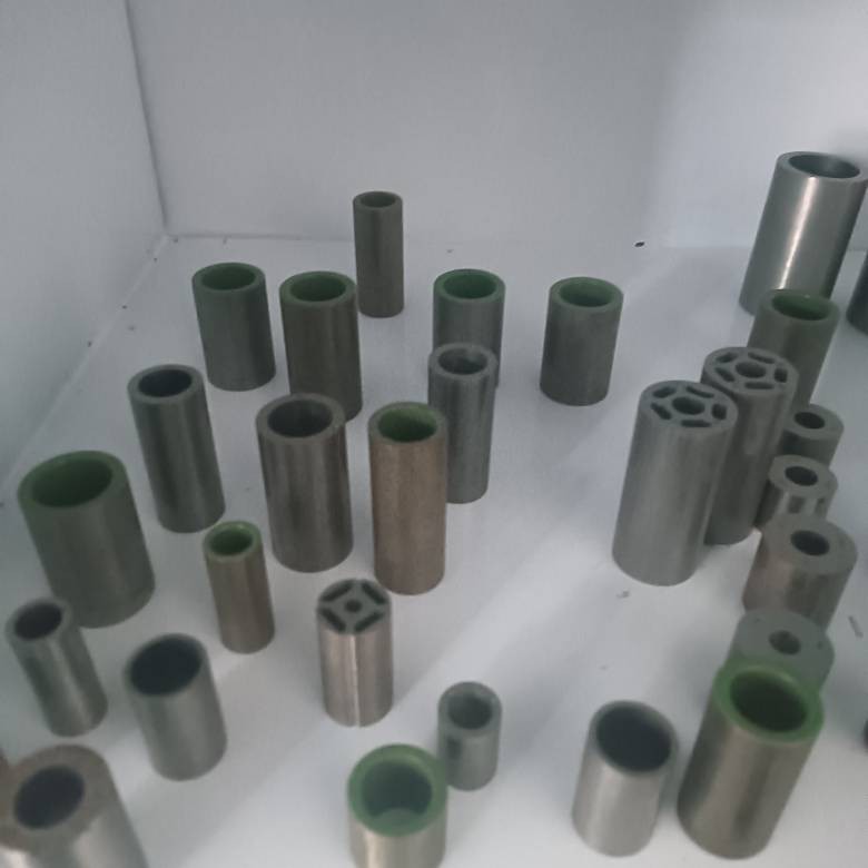
05/18/2024 at 04:16 • 0 commentsImage from one of the suppliers. So, while asking multiple suppliers about custom toroid laminations, I learned some things:
- Prices are typically over the 15USD mark.
- Standard lamination thicknesses seem to be 0.2mm, 0.35mm and 0.5mm, with 0.35 being the most common and 0.2 allegedly costing more.
- One supplier had a list of standard sizes, such as:
- OD = 15, ID = 10.8
- OD = 16, ID = 12.4
- OD = 19, ID = 14
- These were all with 0.2mm laminations. Unfortunately, 16mm is the one that's out of stock.
- 15mm was sounding good because they could supply a 30mm and 15mm length to total to 45mm (and was asking if I could just have 3x 15mm) when I finally got the simulation set up and discovered that power consumption spiked from 120mW to 400mW+ (for a 42mm rotor) just because of that 1mm shrink.
- I think the 30mm length already exists and the 15mm length doesn't.
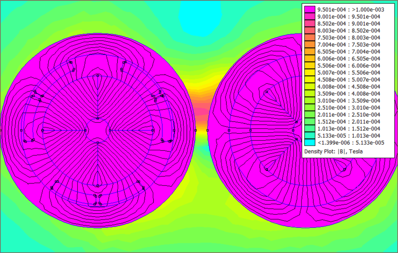
- I decided to try out what would happen if I were to go the other way, and the flux is barely contained at an ID = 12.5 and leaks out if ID = 13.5.
- An ID of 12.5 allows for a 9mm rotor.
- Below is a simulation using yoke material M-22, where purpie is anything over 10 gauss:
I have more confidence that my simulation is set up correctly if there actually is a standard size that's only 0.1mm smaller on the ID.
- The green insulation costs more because a mould needs to be created.
- I got some tolerancing information:
The stator is shorter because the expected PCBA thickness is expected to be 4.95mm. Additionally, I added an extra 4mm to the belt length of Tetrinsic that I've now removed. All in all, this means that the rotor has to decrease from 42mm to 36-37mm.
Due to the larger rotor, the power consumption is still about 120mW.
- Since I'm looking for a toroid, there is also the tape method for making the lamination.
The raw tape material (e.g. the fancy named Supermalloy) ia kind of expensive on AliExpress (such that it's much cheaper to just order the completed toroid from the supplier I found than coil at home).
I looked though the materials in the FEMM materials library and was able to find Stainless Steel 430 where a 400mm x 1m foil is on AliExpress for £21. I'm hoping that I could get a 40mm x 10m for the same price. Below is a simulation with it, and it seems to contain the flux slightly better than M-22.
Each SS-430 yoke could potentially cost only £1.50, as the coil length is 0.707m and 14 lengths could be cut from a 10m roll.
Conclusions
So far, the lowest quote I've gotten is 8USD/ea.
I might want to consider simulating the eddy current losses with just a pure iron tube; since this is a low-speed application, they might not be too bad. At the same time though, it doesn't seem that such a tube exists; I just keep getting different kinds of steel in search results.
The foil coil method would give me the most versatility, and could potentially be used in the larger #Situation SeriouS [gd0098] motorised button without having to once again ask suppliers on Alibaba (unless I need a different length) and probably spend loads on shipping mostly air. Additionally, the foil coil could be directly wrapped around the stator unlike a traditional lamination yoke.
In other news, if I try and compute the expected torque constant to convert the BLDC made in the paper to the current design, I'm about 1/4 off:
Expected    → 75mN.m          [paper torque constant]
            x (9 / 11.5) ^2   [rotor size difference]
            x (37 / 25)       [rotor length difference]
            x (75 / 130)      [coil turns difference]
            = 39.22mN.m

Simulation  = 29.64mN.m       [SS-430 yoke]
            = 29.78mN.m       [M-22 yoke]

Difference  = 24.4%           [SS-430 yoke]
[May 19]
The seller of the SS430 has a 10m listing for 40mm wide which is currently £40 (a little less than 2x the 400mm x 1m). Additionally, it's much more likely that I'd only get 13 completed yokes out of a 10m length. Thus, the expected price is £3.69/ea delivered after VAT, which is still less than the cheapest option I've come across on Alibaba (£4.39 pre-VAT pre-shipping from this supplier). Additionally, I'd have the freedom to experiment; perhaps when attempting to manufacture, I find out that 12.3mm or 12.4mm is better than 12.5mm ID.
For this to work, I'm assuming that the tiny but physical separation between turns will be enough to minimise eddy currents, as discovered in this DIY transformer core video.
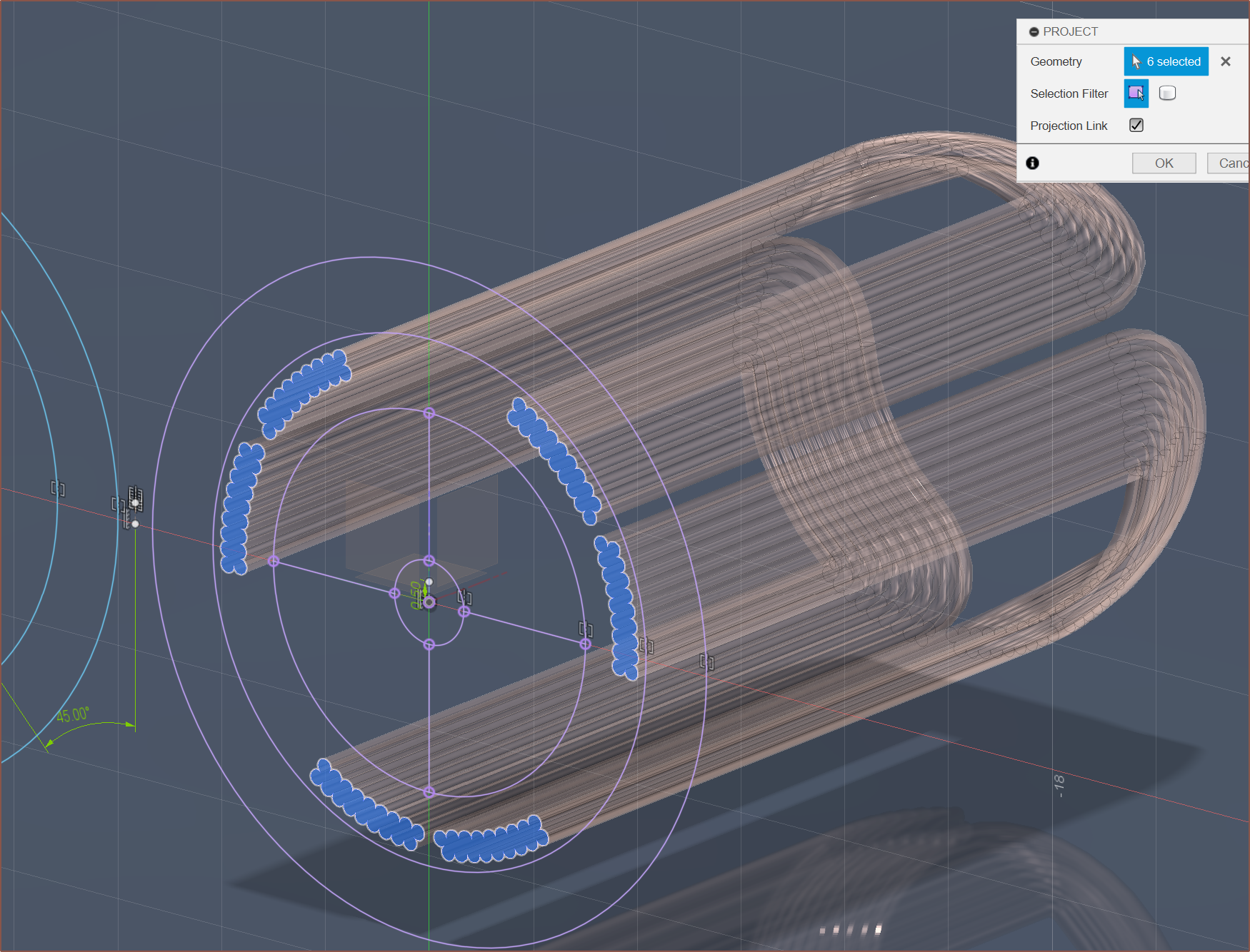
This has been rendered with the yoke as a spiral. Additionally, to make sure that there was enough exposed motor shaft, I've slightly decreased the rotor length and increased the shaft length.
The power consumption is theoretically 122mW and the Kv at 346 with 0.18mm wire (75 turns), meaning that the no-load speed at 5V would be sub 1700RPM. That could be a bit of a problem since the expected max finger speed would be 3400-3500RPM at the motor, so it might mean that power is harnessed from the fingers, causing resistance, or perhaps damage something.
I've also finally redefined the sketch so that it more accurately matches the winding process. 0.25mm wire at 41 turns would have a no-load speed under 3250RPM (460RPM at pulley) and consume 128mW. Additionally, 0.25mm wire is more popular and should be more reliable to wind due to the lower turn count. The lower resistance should also mean it's easier to generate haptic waveforms.
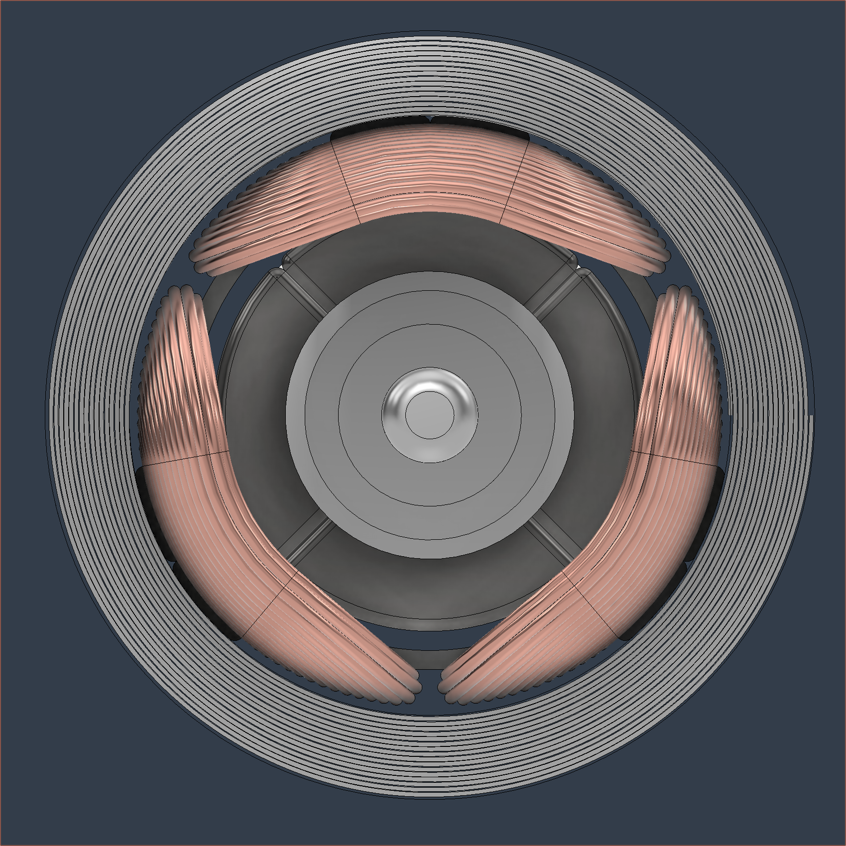
Front view of design with foil yoke and 0.25mm wire. -
[T] Tetoroidiv ribbon cable pinout
05/17/2024 at 17:24 • 0 comments- 5V
- I2C Data
- I2C Clock
- GND
- I2S Clock
- I2S Word Select
- I2S Data
- GND
- SWD Clock
- SWD Data
- 5V
This was laid out so that:
- there was less chance of something being damaged if the ribbon cable was soldered/inserted backwards,
- communication, audio and debug pins are exposed, and
- clocks are next to ground pins to reduce crosstalk.
- I looked into Word Select and it seems to be either high or low for many clock cycles, so that's why I've put it in-between the I2S clock and Data.
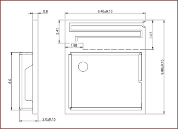
I believe 1mm pitch would be the best ribbon cable to use, and an 11P one should be 12mm which should be the same as the expected length of the PCB (similar to the Tetrinsic PCB I designed last year, but its cable was on its width).
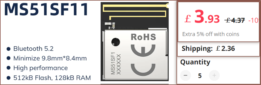
I'm going to rely on the internal antenna of the MS51SF1 for the time being, since similarly sized Bluetooth dongles and earbuds seem to have decent reception despite their small size. Thus, I haven't added an antenna pin to the pinout.
-
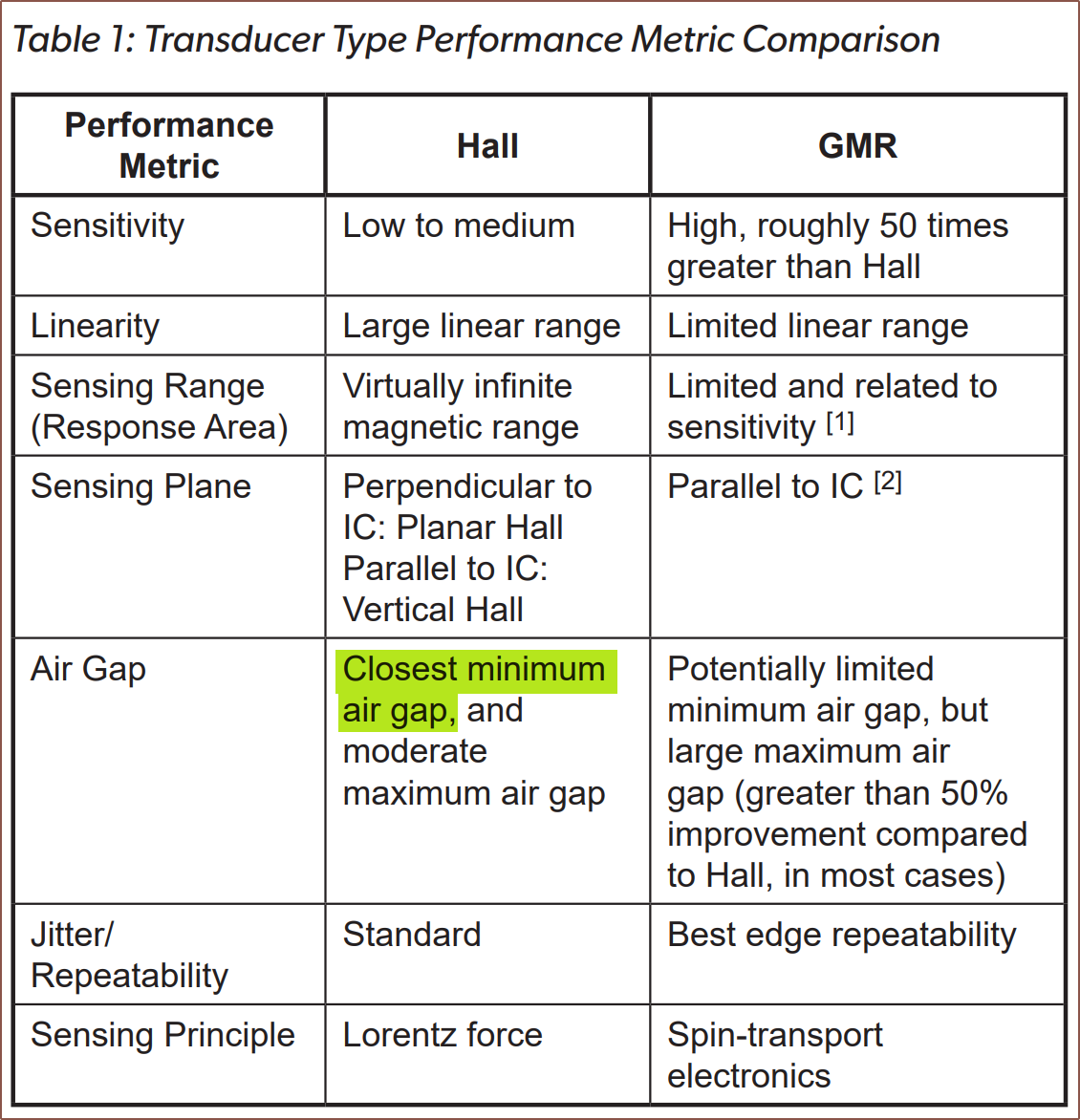
[T] MT6701 vs TLE5012B magnetic encoder
05/17/2024 at 06:25 • 0 commentsBecause of this post, the below table, the reduced cost (£9.50 vs £12.50 for 10pcs on AliExpress), the increased speed (mentioned below) and its tried-and-tested-ness in SmartKnob View, I'm thinking of going with the MT6701.
Source Both of them support SSC, which essentially sounds like 3-wire SPI. In both 3 and 4-wire SPI, one of the wires is the chip select pin. Well, considering that there's only 2 chips that need SPI connectivity and that (if I'm reading the nRF52833 specifications correctly) the SF11 module supports 4 SPI buses, it makes more sense to give each chip its own bus and omit the CS pins, thus the amount of pins I need to route would stay the same but I'd get more throughput and the encoder interface won't negatively impact the BLDC controller interface.
Additionally, the minimum clock period of the MT6701 is 64 nanoseconds, which corresponds to 15.625Mbit/s transfer speeds -- almost twice the 8Mbit/s of the TLE5012B.
It might make sense to run the MT6071 at the same max clock frequency as the DRV8311, which is 10MHz, so that they can be driven by one clock source peripheral. Each message is 24 bits on the former and 32 bits on the latter, resulting in a maximum of 416.6K and 312.5K messages per second respectively. That should be more than enough bandwidth to get the job done.
-
[R] Bluetooth modules such as NRF2833 MS51SF1?
05/16/2024 at 11:50 • 0 commentsI can think of 3 ways to go about a controller solution for #Tetrinsic [gd0041]:
- The expectable way: A small, low-cost MCU on the same PCB as the angle sensor and BLDC driver.
- The exciting-on-paper way: A BLE module on the same PCB as the angle sensor and BLDC driver.
- The monolithic way: The angle sensor on its own and all control via a single MCU on the main board.
Now I say "exciting on paper" because it would make Tetoroidiv a bluetooth- and zigbee-enabled servo. The reasoning is because of the benefits they offer: the modules are off the shelf (thus simplifies assembly and testing) and it then means that the main board (e.g. the Tetent/Tetrescent PCB) doesn't need an additional BLE module.
The "expectable" strategy means that 3 different microcontroller toolchains would be needed for the final product, whereas the "exciting on paper" strategy would reduce that to two and simplify the design of the main board due to more PCB surface and trace space.
The monolithic way would need 2 toolchains too since there's not a bluetooth and LCD-controller enabled microcontroller, but would allow better utilisation of the peripherals in the U5G9. The downside is potential SPI-bus bottlenecks.
ESP32C6
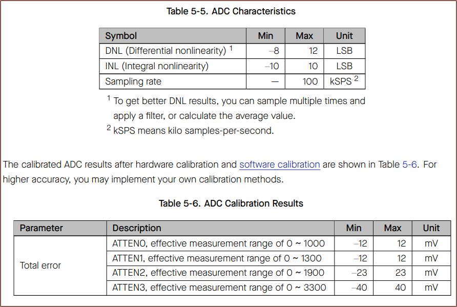
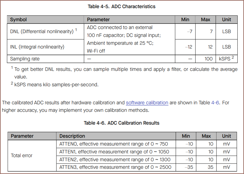
Understandably, the strategy I originally thought of was the ESP32C6, as it's only about 50p more than the ESP32C3 and has more features (including a motor peripheral, allowing 6PWM motor control if needed) whilst keeping the same sized module. My main reservation was that the ADCs that Espressif make have a poor reputation. It took a while to even find the characteristics, which weren't in the larger Technical Specifications.pdf but in the smaller datasheet one:
ESP32C6 ADC Characteristics They seem very similar to the C3 ADC:
Now I looked into SimpleFOC and hear that the C3 is kind of decent. I've also now done some research on what those DNL numbers mean and it turns out that lower is better. It basically means the tolerance around the correct digital value. For example, if a 1.0V analog signal should be converted to the number 1000, the C3 could actually read between 993 and 1007. I still have yet to fully understand what INL represents.
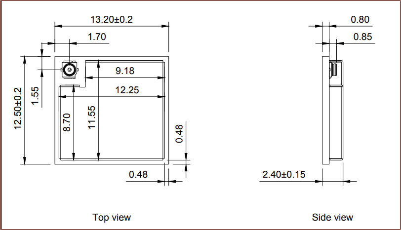
nRF52833
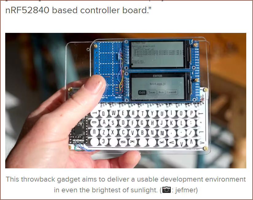
Anyway, I was reading about PDAs powered by microcontrollers (such as the one above) and remembered that the nRF52 line of chips also existed so I went to go see what the smallest module was and I found this:
This module has an antenna pin should I need it, but the whole thing with antenna is smaller than the C6 without so I will try using the PCB antennas first. This module is over 2X that of the C6, but in absolute terms, it's about £20 per pair of Tetents.
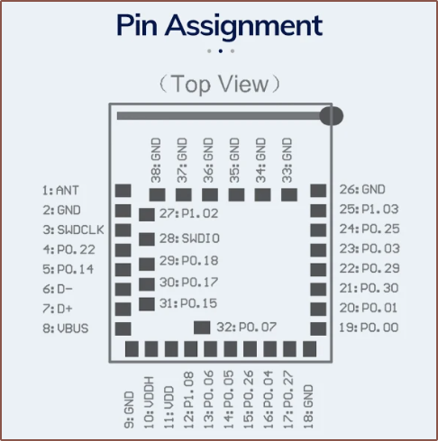
I've also heard that STM32s have good ADCs, and the STM32WB5MMG is a module that only comes in at 7.3 x 11mm, but the price seems to be over £9/ea.
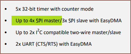
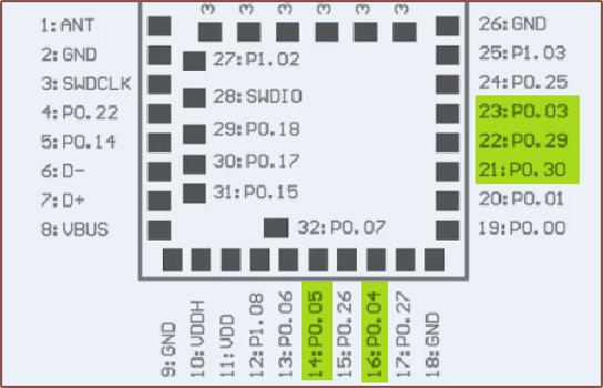
Back to the SF1 module, it does seem that there would be enough pins to reasonably connect all components:
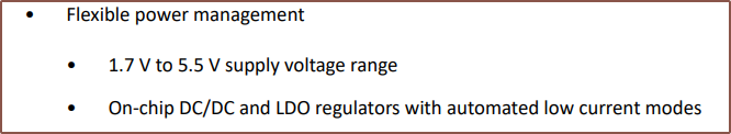
Additionally, like all the other chips and components, it can run off 5V:
It also seems to use 2-wire firmware upload, whereas the C6 would also need a BOOT and RESET pin (since there's no space on the board for buttons). Additionally, there is a Rust HAL for the nRF52 chips.
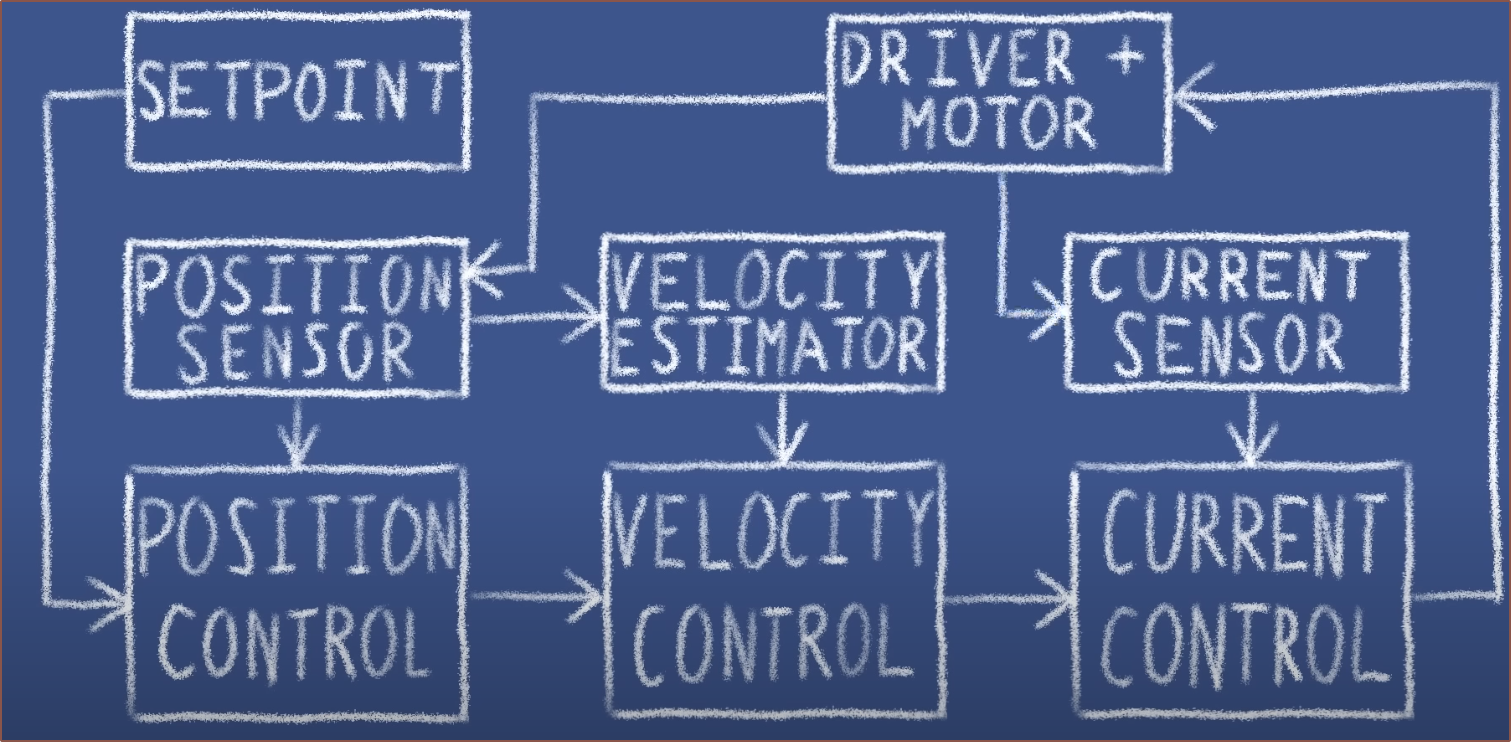
The ADC sounds good. For starters, it supports 8 single-ended channels or 4 differential channels, as well as oversampling. It sounds closer to the specifications of a discrete ADC than what feels like an afterthought in the Espressif line. It seems that, instead of the C6 having to compute the average of the input signals, I'd be able to do something like set a 16x oversampling and achieve 4kSPS per channel (thus 192kSPS total speed), where that specific sampling frequency is chosen to match what was used in the YouTube video of this servo project:
The first two happens at 4kHz and the current sense is 50kHz as the response is faster and doesn't rely on physical movements. My plan is to target a minimum realistic speed for everything from sensor acquisition to motor control, and 4kHz sounds like a reasonable frequency to aim for.
The module itself seems to have 5 of the 8 analog pins exposed:
Thus, it's possible that an analog method for sensing the rotor orientation (SinCos voltages) could be used with 5kSPS/channel and 8x oversampling. It's probably better to get an all-in-one chip though.
[May 21] This article on the FOC algorithm suggests that the steps are executed between 15 - 20kHz, so it sounds like I should do 4x oversampling for 16kSPS/channel. SimpleFOC just says "the faster the better" in a comment in its sample code, also noting that the "Arduino" can do 1kHz and the "Blue Pill" can so 10kHz.
-
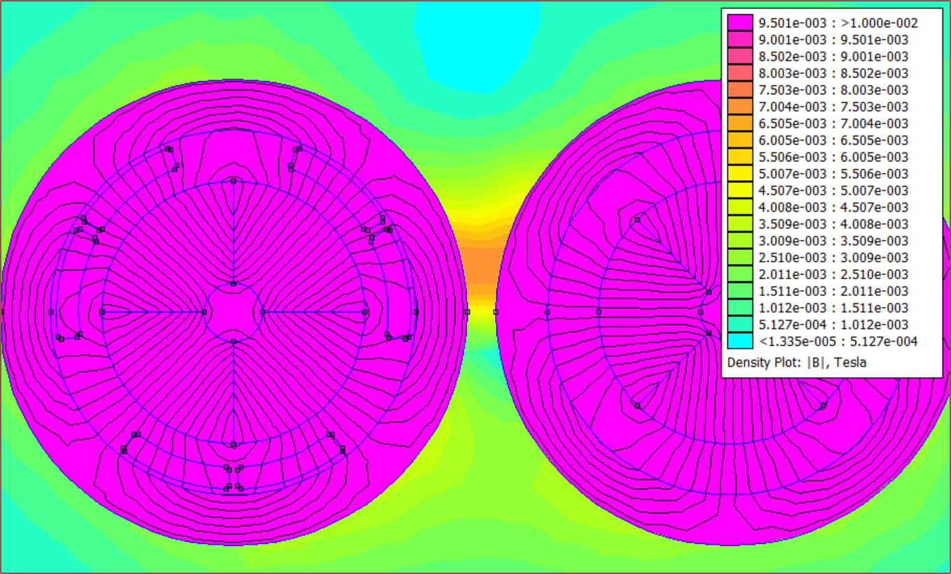
[M] Magnetic interference with ferrite toroids
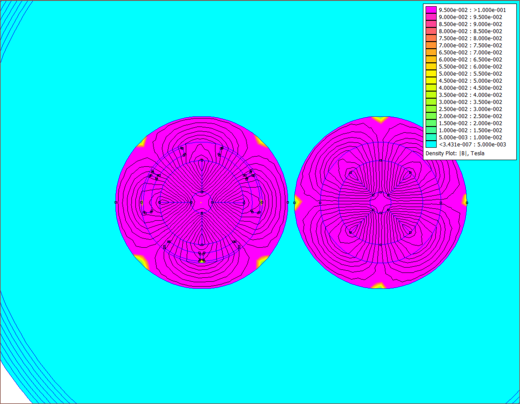
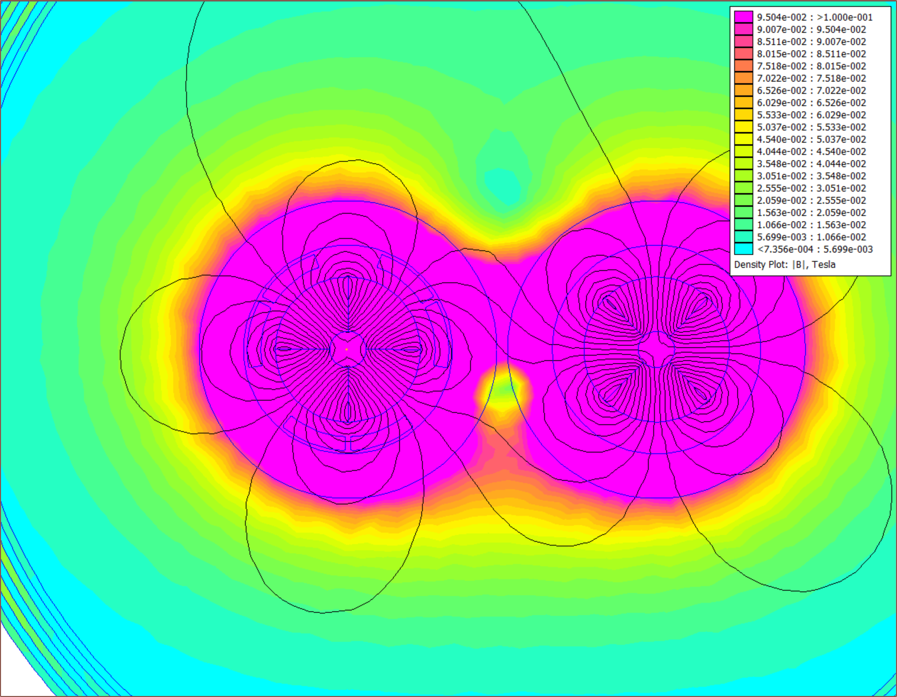
05/14/2024 at 02:50 • 0 commentsUnlike the original simulation, the actual motors are not by themselves in free space and I was wondering if the magnetic field outside the motor was going to cause issues. It does. Below are screenshots in steps of 15 degrees for a rotor with a 17mm centre-to-centre distance:
![]()
The colours have been capped os that anything over 1000 gauss is purple. I also got torque values and the fluctuation was a very significant: 26.0 +/- 6 mN.m.
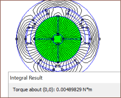
I decided to see what "M-22" laminations would be, as mentioned in the BLDC FEMM tutorial, and the difference is massive:
The flux is completely contained and the torque about the rotor is 29.8 mN.m. At least I know that the ferrite toroids can get 87% the torque of proper laminations but leaks a magnetic field.
This is in utter contrast to the stainless steel 304 tube idea:
-
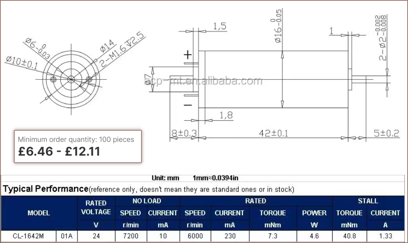
[R] 1642 brushed motor?
05/12/2024 at 07:26 • 0 commentsI have looked into brushed motors (shown as copper-coloured lines) since their control requirements are much lower, and the CL-1642M motor is the most ideal assuming that the resistance of the coils can be calculated as [rated voltage] / [stall current]:
The reason why it's ideal is because it has a 2mm dual shaft, making it straightforward to add both a magnetic encoder and POM gear, as well as using the lowest power out of all the commercial offerings.
The main downside is that the supplier doesn't sell samples at all.
-
[B] Custom rotor
05/11/2024 at 17:57 • 0 commentsWhen I was searching for suppliers for the 4-pole rotor magnet, ABM Magnetics unexpectedly offered to create the entire rotor during conversation. Another thing that the engineers suggested was to split the rotor magnet (which was 58mm at the time, before the new 7.2 : 1 reduction):
I communicated with our engineers and our suggestion is to divide the 58mm long magnet into 3 equal sections for the following reasons:
1. Because the size of the magnet is OD8, ID3mm, and length is 58mm, the magnet is easily broken during processing;
2. Dividing the magnet into three sections can reduce eddy currents and reduce the power consumption of the motor.
When the magnet was shortened to 42mm, I suggested that the rotor be made from 8 magnets total (2 equal sections of 4 magnets). They're also planning to install the bearings too, so the complete solution would look something like this:
They never mentioned price until today (I was thinking that it was going to be in the thousands but I'll stick around for the conversation anyway), but it's actually $16/rotor for 10pcs. I haven't asked about shipping price but I'm assuming it's another $50 on top.
It seems every motor option for "new" and not "new old stock from AliExpress" is going to be £20/motor and up, and the DIY Tetoroidiv probably would be no exception since everything else about the motor (3D print, toroids and coils) cost pennies. The 5 toroids needed probably amount to £1 total, and even when printing in £40/kg PBT, I'm not sure that the overmould would even scratch 10p in cost.
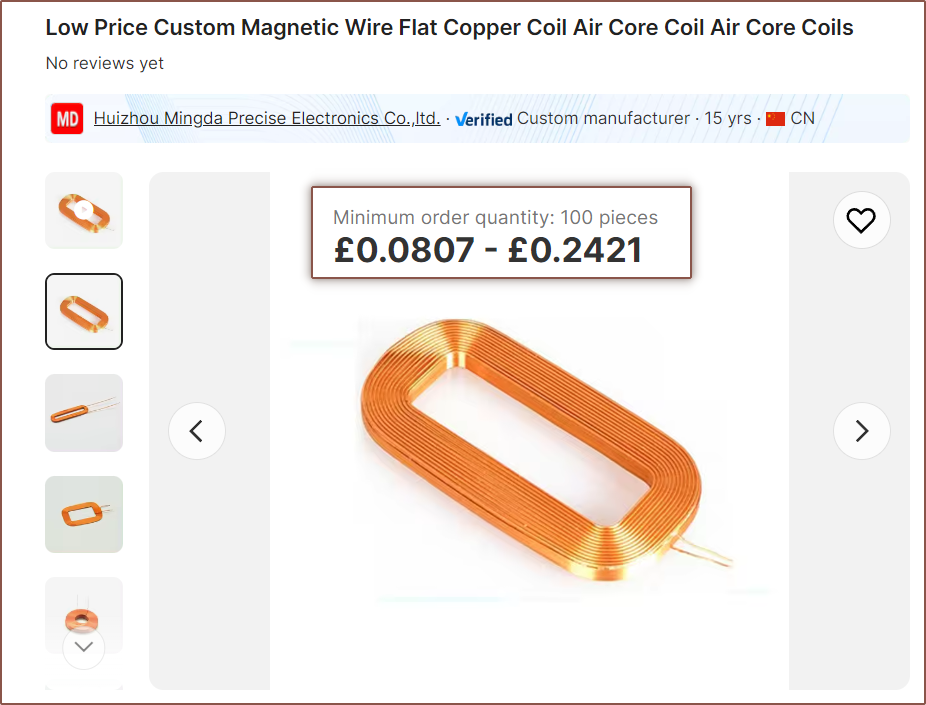
I'm also seeing if there is a possibility that I could acquire and use air-coils instead of having to coil at home.
Tetoroidiv [gd0152]
A Ø16mm BLDC servo motor with Bluetooth v5.2 and zero cogging.
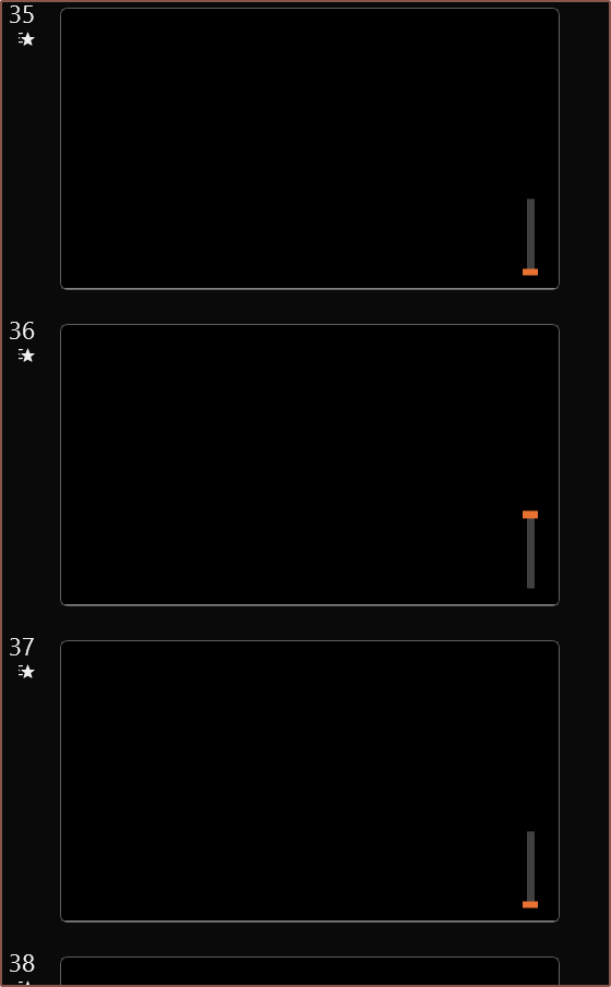 So I had the idea to actually create a simple PowerPoint animation where the orange bar would slide up and down 50mm with a smooth start/end transition to account for acceleration. Then, the time duration of both the animation and the transition to the next slide would be changed so that it looks like my finger is actually moving the slider. I found that a 0.12s animation and 0.14s slide transition achieved this without my finger doing any particular effort.
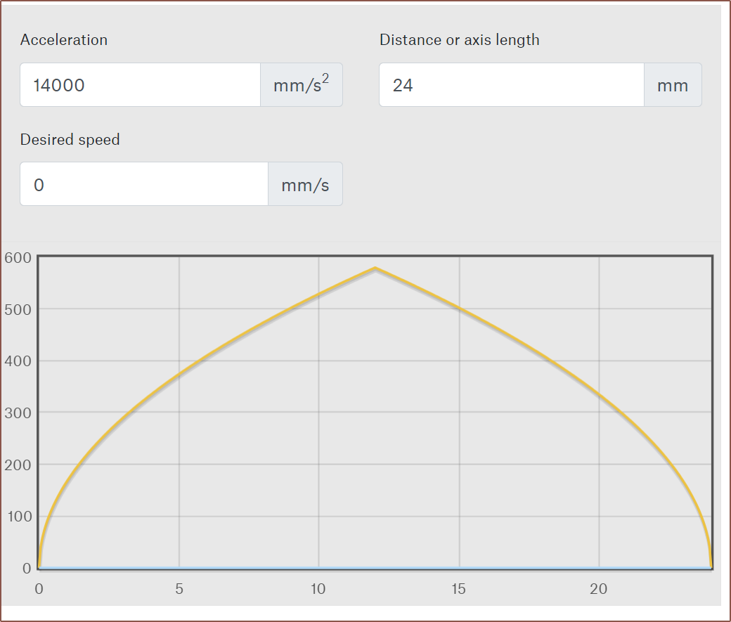


 I have more confidence that my simulation is set up correctly if there actually is a standard size that's only 0.1mm smaller on the ID.
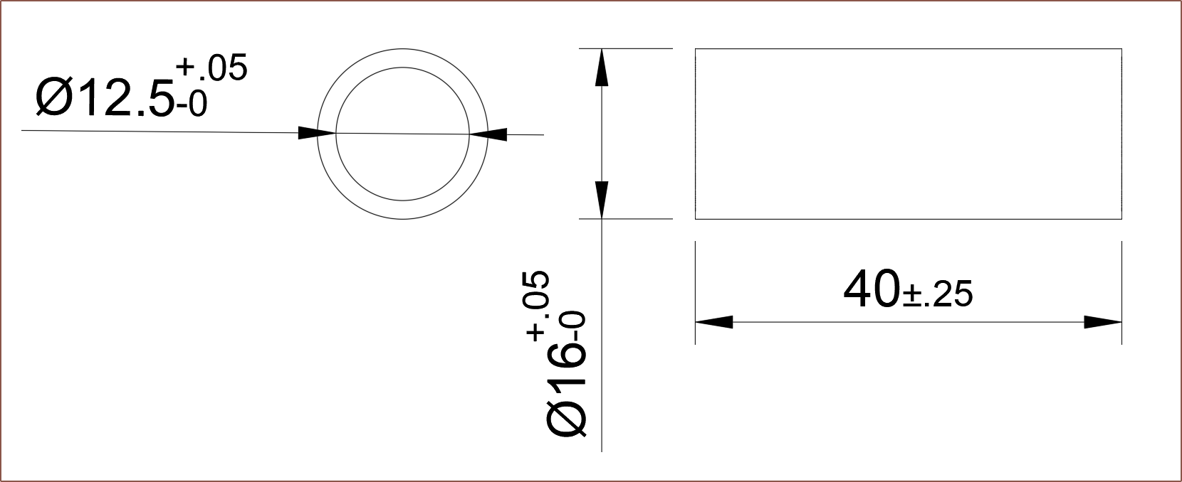 The stator is shorter because the expected PCBA thickness is expected to be 4.95mm. Additionally, I added an extra 4mm to the belt length of Tetrinsic that I've now removed. All in all, this means that the rotor has to decrease from 42mm to 36-37mm.
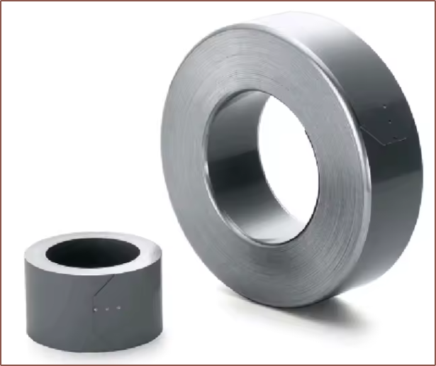
 Each SS-430 yoke could potentially cost only £1.50, as the coil length is 0.707m and 14 lengths could be cut from a 10m roll.