 kelvinA
Navigation
Prior Reading
- [R] Frameless VS Slotless BLDC
- [B][M][R] Custom 16mm Slotless?
- [R] 1656 18W BLDC and controller considerations
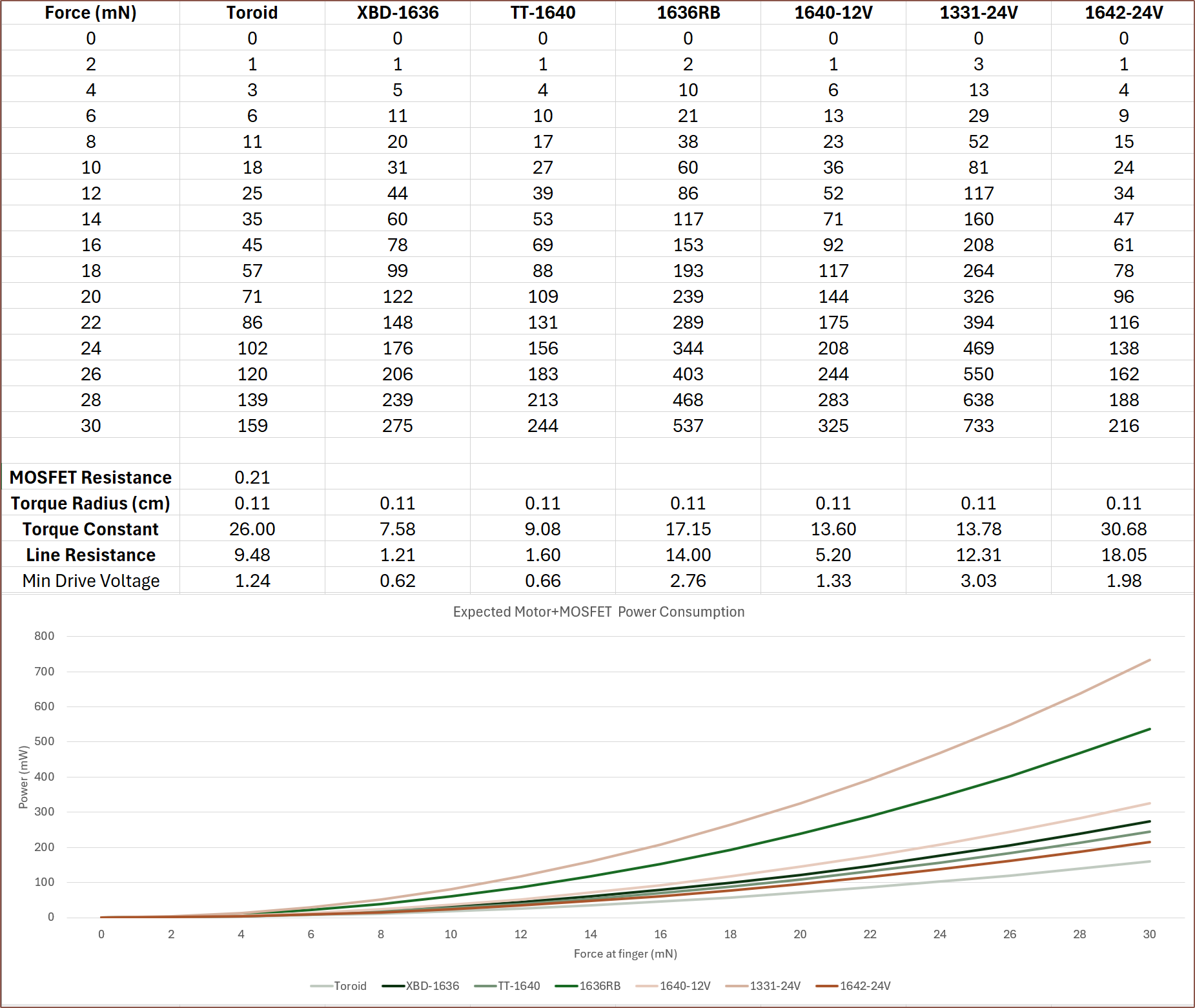
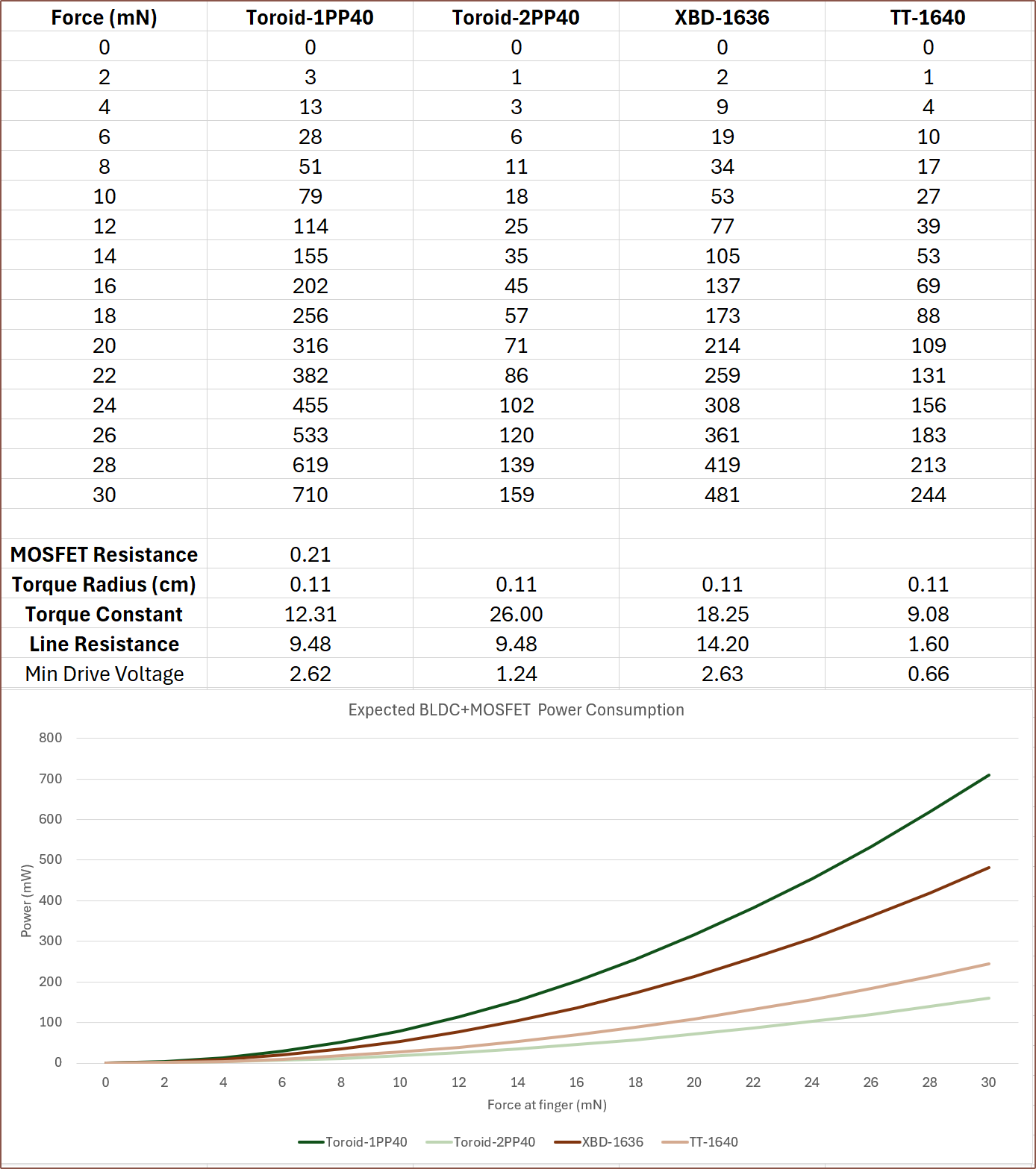
- [T] More accurate power estimates
Contents
The title tag system is explained here, and the table is updated when a change occurs. Notable logs have bold L# text.
Preface
[2024 - May 1]
Welcome to the 3rd level of "project in a project", or the 4th depending on how you look at it:
- #Tetinventory [gd0039]
- #Teti [gd0022] [The Main Project]
- #Tetent [gd0090]
- #Tetrinsic [gd0041]
- Tetoroidiv [We Are Here]
- #Tetrinsic [gd0041]
- #Tetent [gd0090]
- #Teti [gd0022] [The Main Project]
This project is the merge of a 16mm BLDC motor and "Tetrinsic PCB", currently now responsible for driving said motor as well as the following needed for #Tetrinsic [gd0041].:
- controlling an addressable LED strip
- reading the orientation of the BLDC rotor
- reading a force sensitive resistor
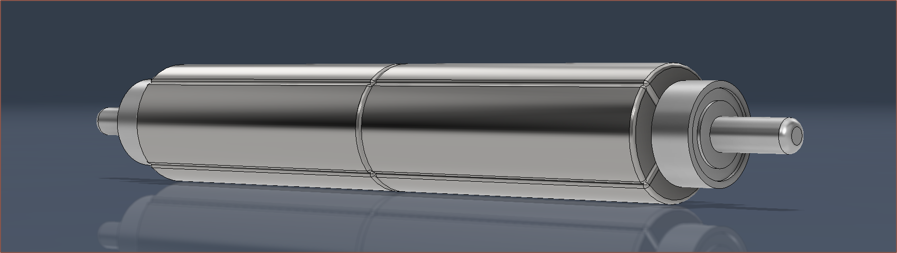
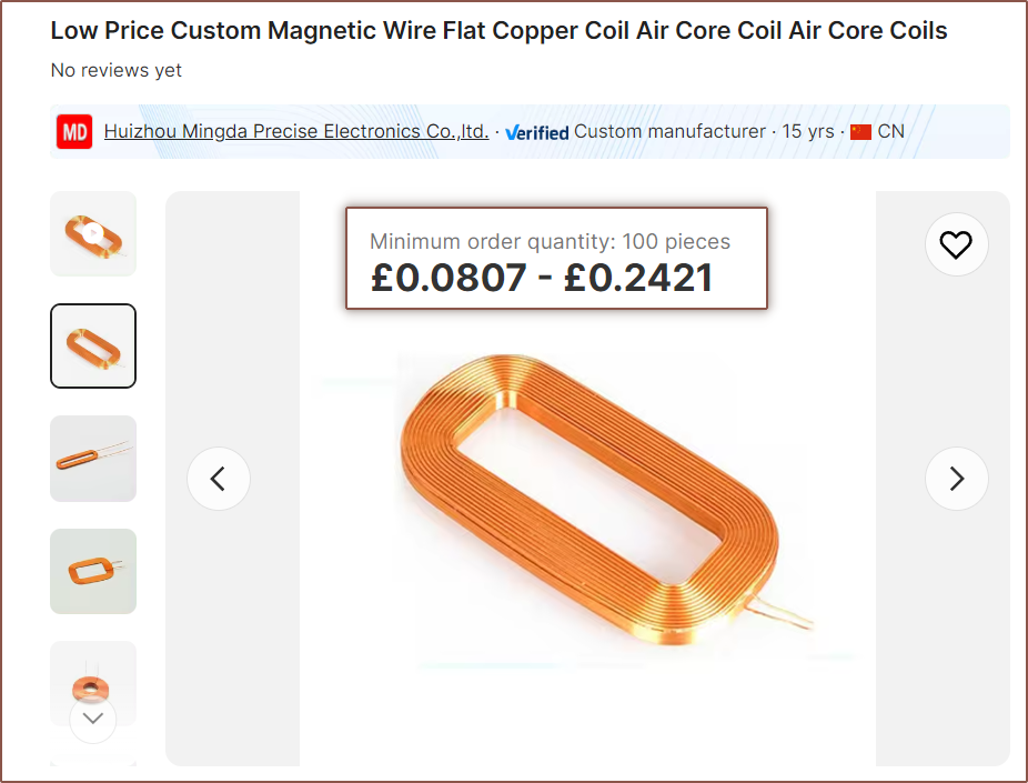
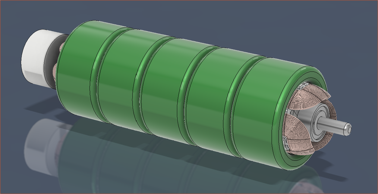
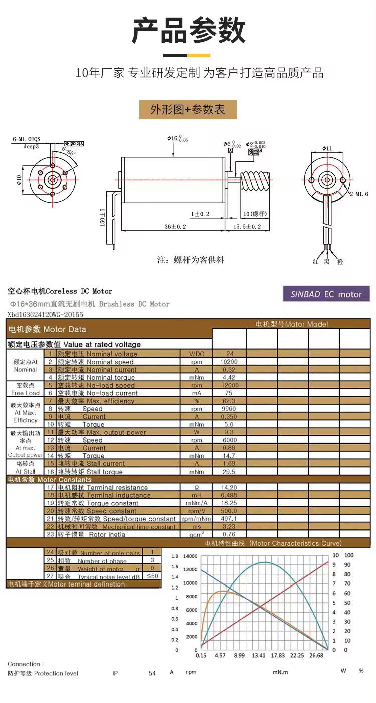
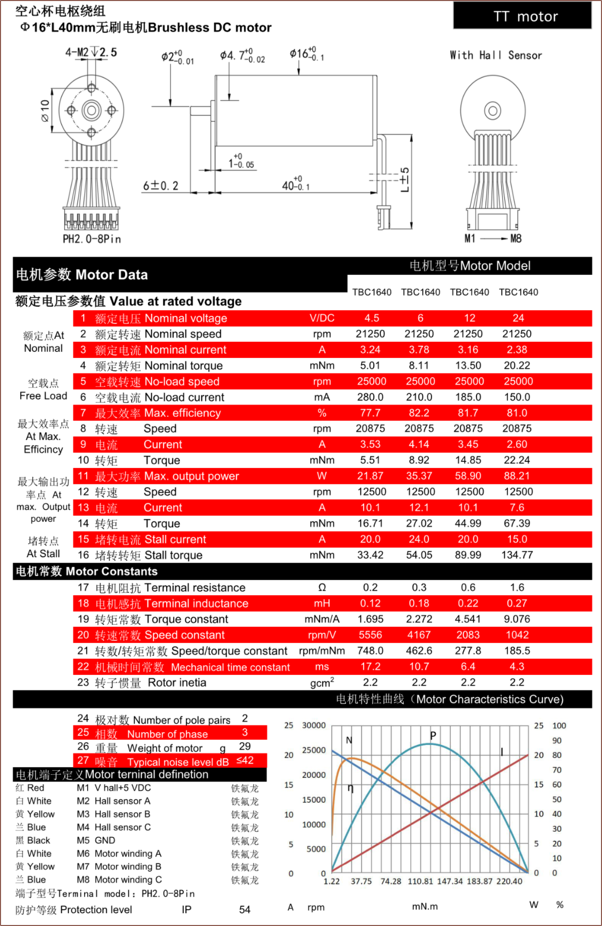
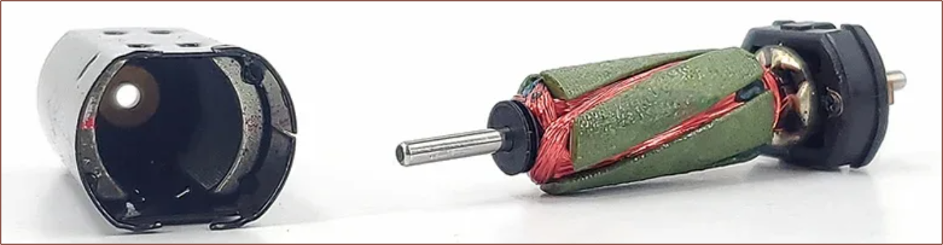
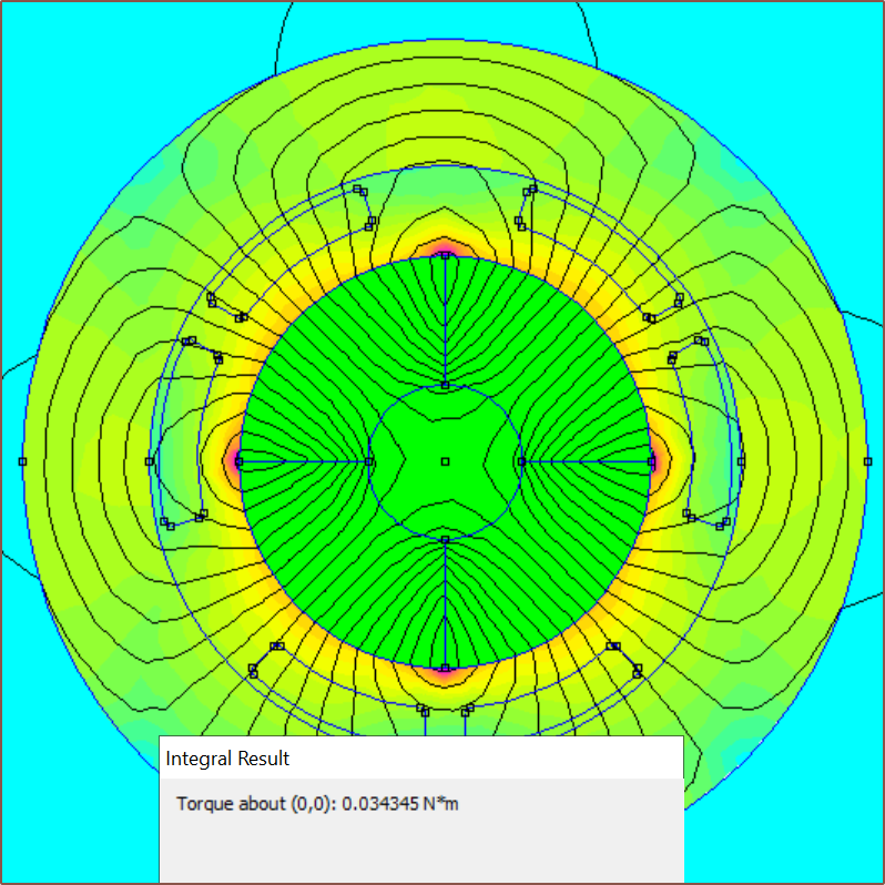
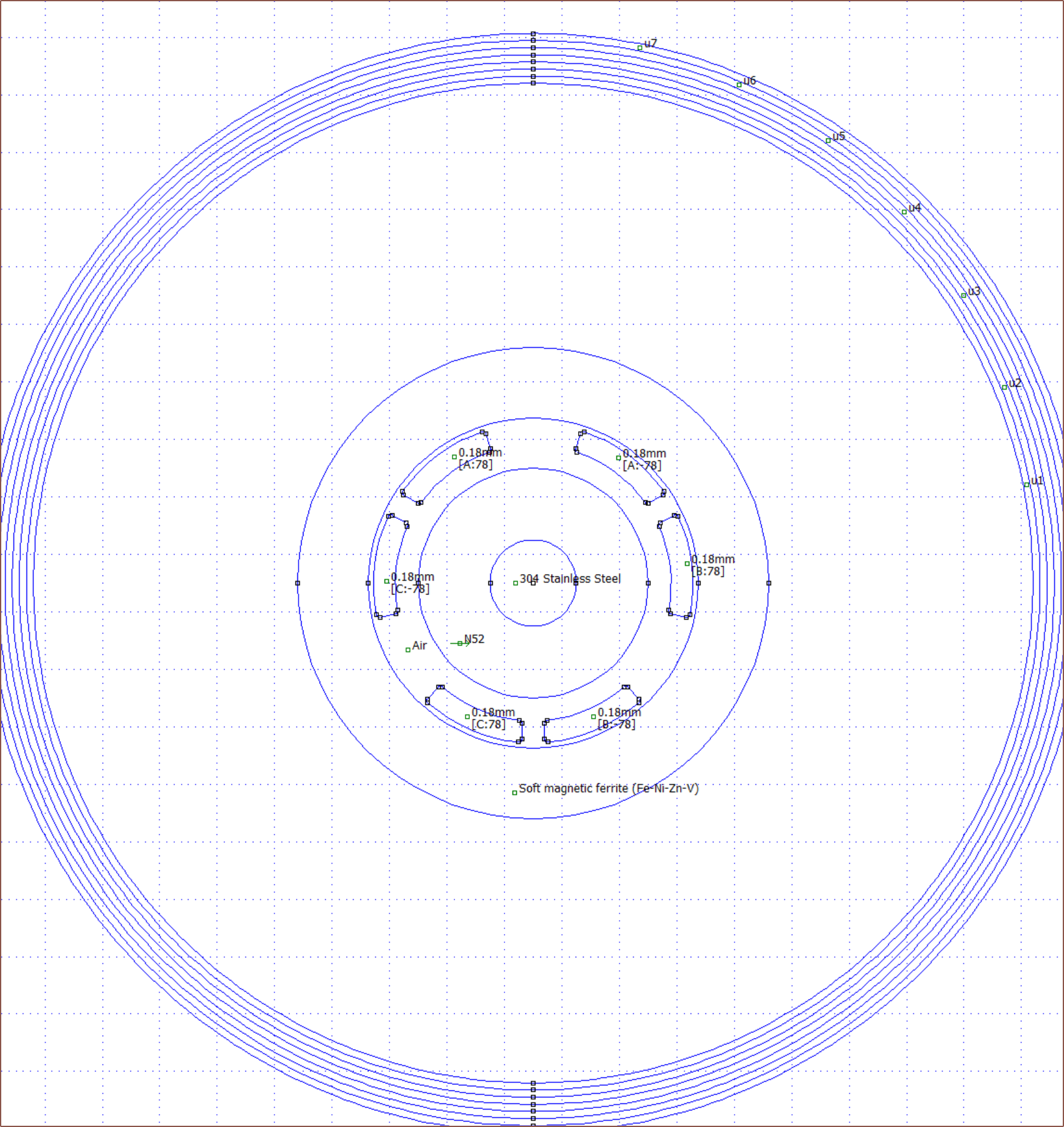
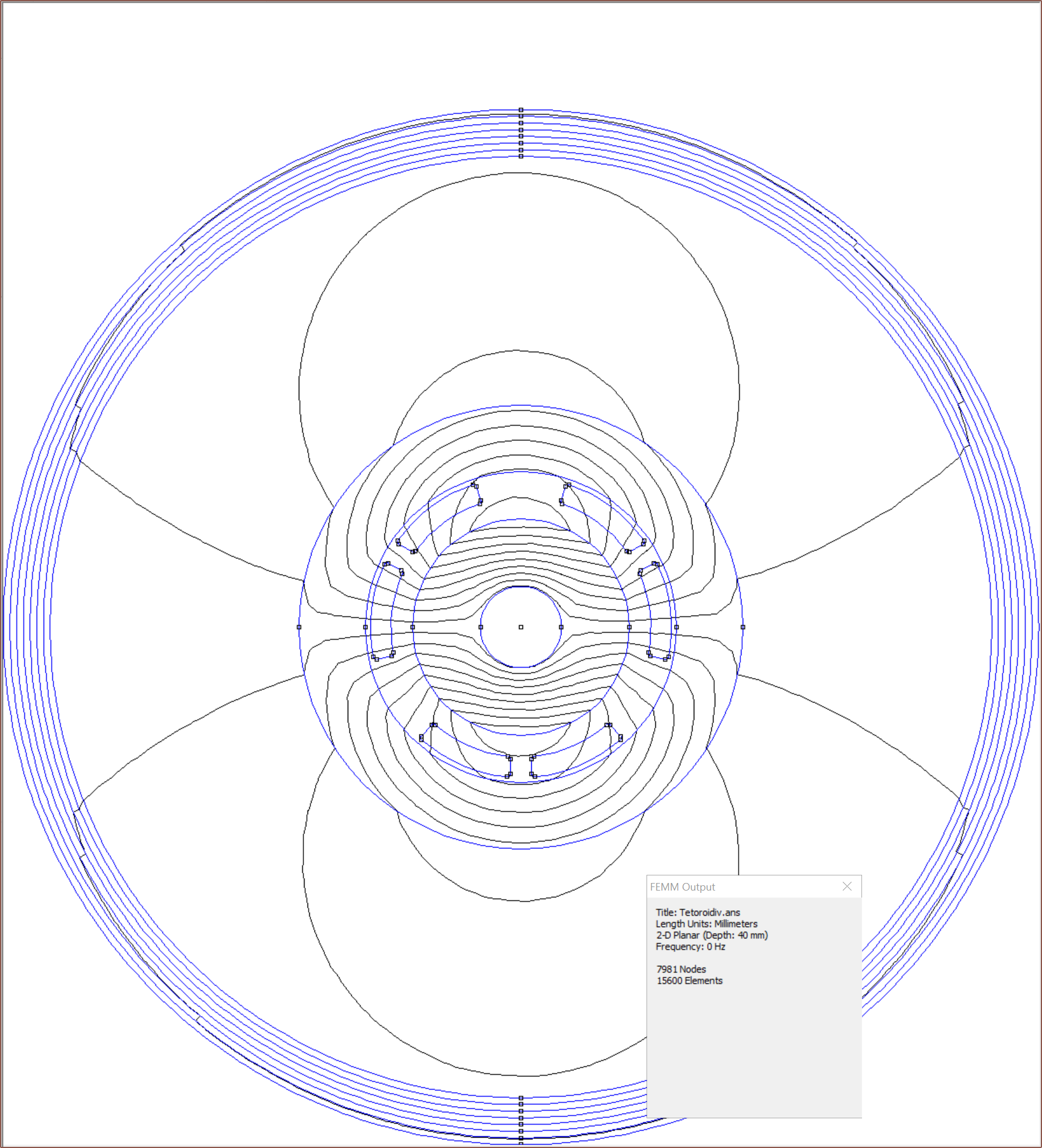
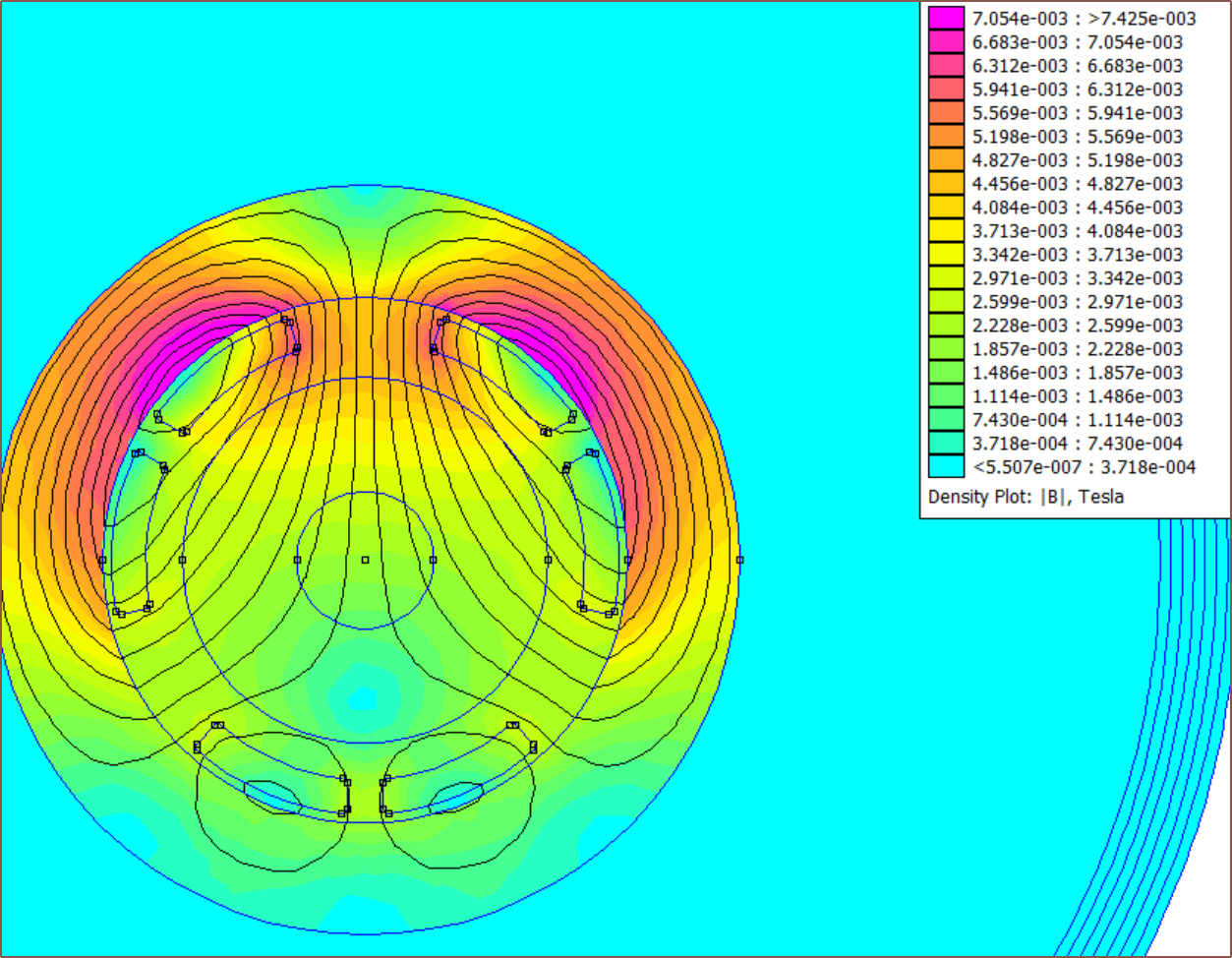
The name is the merge of "toroid" and "derivative", with the former being because of the ferrite toroids (aka ferrite core or ferrite ring) that are used in place of traditional laminations for a slotless motor, and the latter because it's like a "3rd order differential" (if you consider Tetinventory as an integration) of the Teti project.
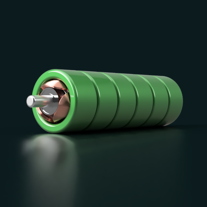
I'd rather not DIY a motor here, but the name is likely to stick even if I am able to acquire a commercially available motor, as the goal is to combine a 16mm BLDC with the custom PCB.
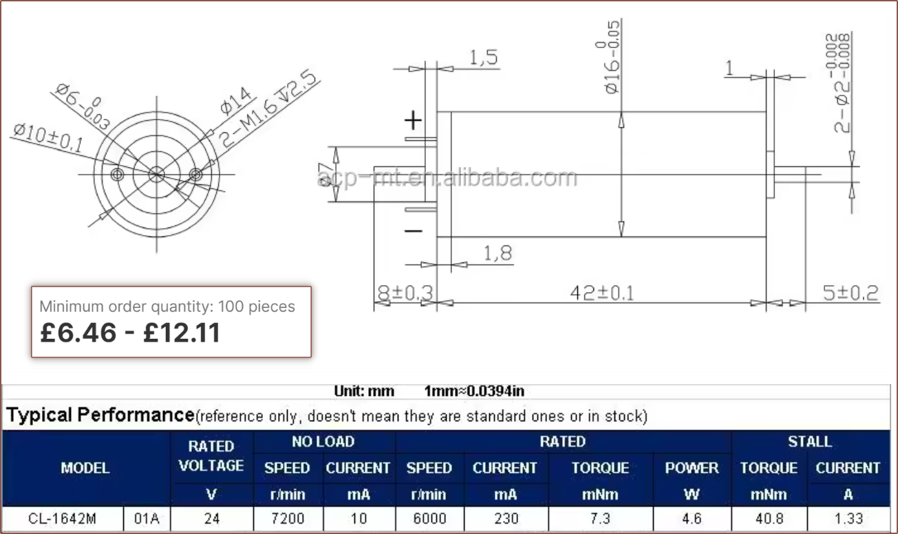
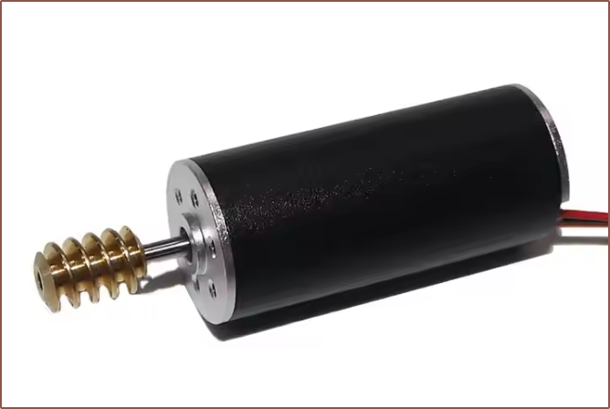
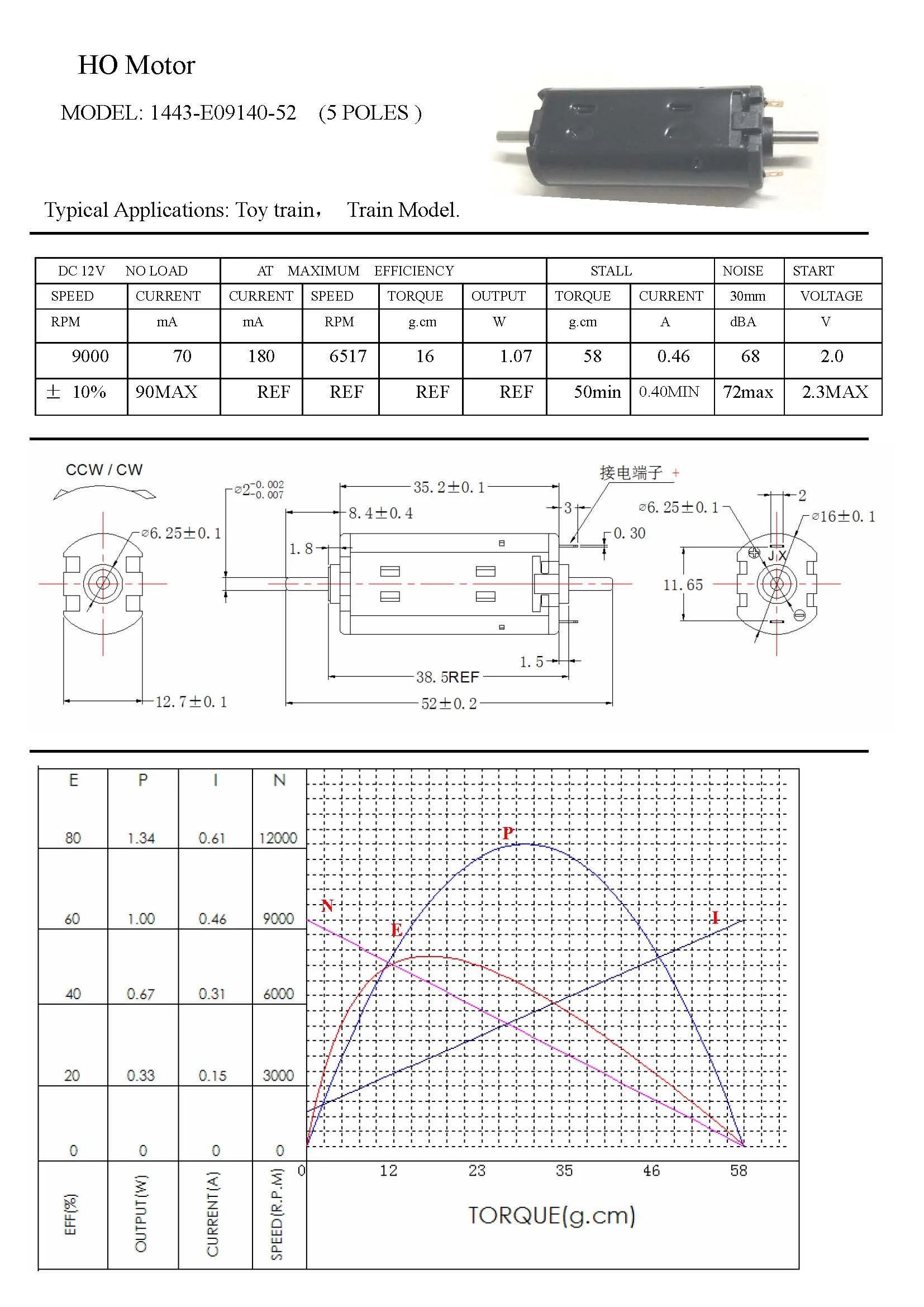
At the time of writing (and still the case 2 weeks after), 16mm motors (brushed and brushless) between lengths 36 and 59mm are only available directly from manufacturers (e.g. on Alibaba), and the prices are high (>£30/ea) considering I'd need 8 for a pair of Tetent's and 10 for a pair of Tetrescent's.
 Scott Duckworth
 Daren Schwenke
 Krockwell