Mike Hendricks
-
Mapping limited potentiometer value to a number line
08/21/2014 at 05:28 • 0 commentsArduino reads potentiometer values from 0 to 1023. If you want to use the potentiometer value to drive a number input in Motionbuilder, you have to choose the range you want control over. This means you have a limited range of values to work with.
What if you wanted to use the same potentiometer to drive multiple values? For example you have two cameras, and the pot value controls the fov. You rotate the pot to 512 setting the fov on the first camera. You then switch to modifying the second camera. If the second camera was set to 100, as soon as you rotate the pot the camera will jump from 100 to 511.
Additionally what if you want finer control? Say if you want the full range of the pot to be half of the current range.
The best solution I can think of is using some sort of rotary encoder like the scroll wheel of a mouse. This would be the simplest and easiest way to handle this, however I came up with using a sliding offset when mapping your pot value to the object value.
For this to work you need a pot, and two buttons(Offset, and High Res). When you rotate the pot it adjusts the value mapped between offset and offset + resolution. While holding "offset" when you rotate the pot it adjusts the offset but the value remains the same. While holding "High Res" when you rotate the pot it will adjust the value but the resolution will be half the size it currently is, allowing you to adjust the value with more control. Given your offset = 5, resolution = 10, value= 10, and your pot is at 50% rotating the pot to 0% with "High Res" pressed(multiplying resolution by 0.5) will result in your value being set to 7.5. The same rotation without "High Res" pressed would result in the value being set to 5.
To calculate this you need 4 pieces of information.
- The current value
- The offset. This is the value when your pot value is 0
- The resolution. This added to the offset will be the value when your pot value is 1023
- The Multiplier: This value is used to shrink the resolution
Here is a python example of how to map the values.
class Camera:
	def __init__(self, value, offset, resolution):
		# current value of the camera(Fov for example)
		self.value = float(value)
		# the offset value is mapped to zero on the pot
		self.offset = float(offset)
		# offset + resolution is mapped to 1024 on the pot
		self.resolution = float(resolution)

	def mapVal(self, x, mult=1.0, in_min=0, in_max=1023):
		# update the min and max values to map to the pot value
		out_min = self.value - ((self.value - self.offset) * mult)
		out_max = out_min + self.resolution * mult
		# Map the pot value to your number line value
		out = (x - in_min) * (out_max - out_min) / float(in_max - in_min) + out_min
		return out

	def updatePotVal(self, value, offset=False, resMult=1.0):
		if offset:
			val = self.mapVal(value, resMult)
			self.offset += self.value - val
		else:
			self.value = self.mapVal(value, resMult)
<p>>>> a = Camera(5, 5, 10)
>>> a.updatePotVal(512)
>>> print a.value, a.offset, a.offset + a.resolution
10.0048875855 5.0 15.0
>>> a.updatePotVal(0, resMult=0.5)
>>> print a.value, a.offset, a.offset + a.resolution
7.50244379277 5.0 15.0
>>> a.updatePotVal(1024, offset=True)
>>> print a.value, a.offset, a.offset + a.resolution
7.50244379277 -2.5073313783 7.4926686217
>>> a.updatePotVal(512)
>>> print a.value, a.offset, a.offset + a.resolution
2.49755620723 -2.5073313783 7.4926686217</p>
-
Everything connected
08/20/2014 at 06:06 • 0 commentsThis video shows the control after I got all of the components connected and testing with telnet. It shows how I can turn on the Record LED from the computer. Unfortunately I ran into problems trying to open a second connection to the Arduino from inside motion builder to send the control character. So far I haven't been able to figure out how to connect to a event in Motionbuilder that will notify me when Motionbuilder is recording.
-
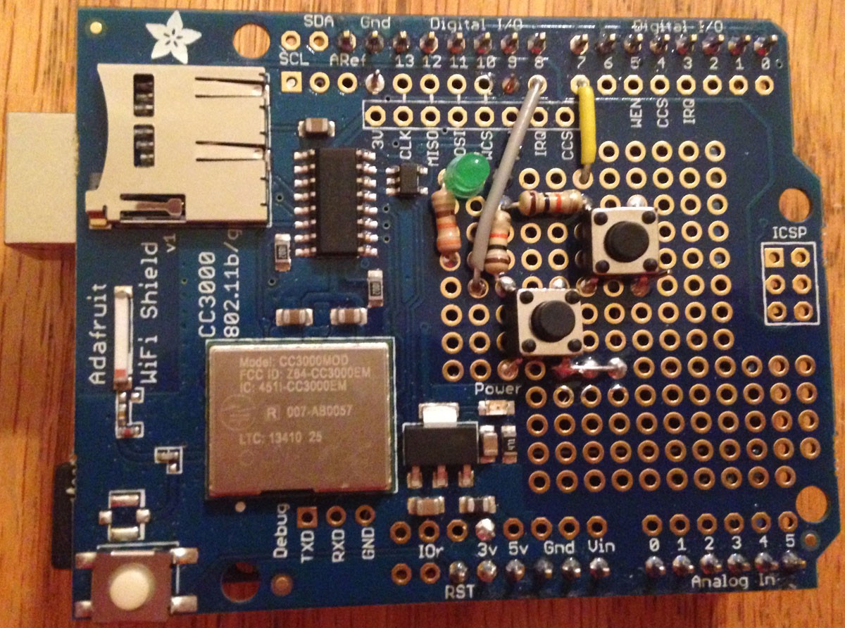
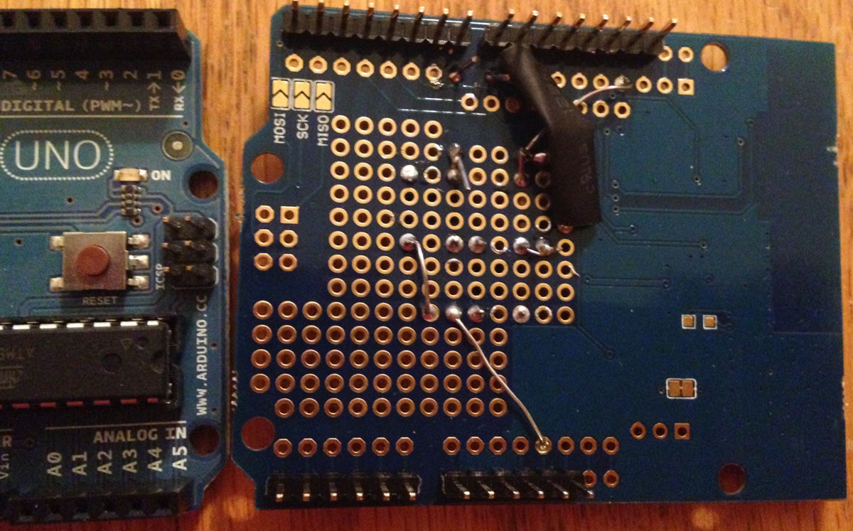
Early Prototype
08/20/2014 at 05:19 • 0 commentsFor the first version of this project, I bought an Arduino shield version of the CC3000 and attached it to a Arduino Uno I had laying around. I soldered a couple of buttons to the breakout board and a LED that turned on while the device was booting, and turned off once the device received its IP address.
This version gave me a proof of concept and allowed me to plan out the next version of the WiFi control.
![]()
![]()
-
Basic Design
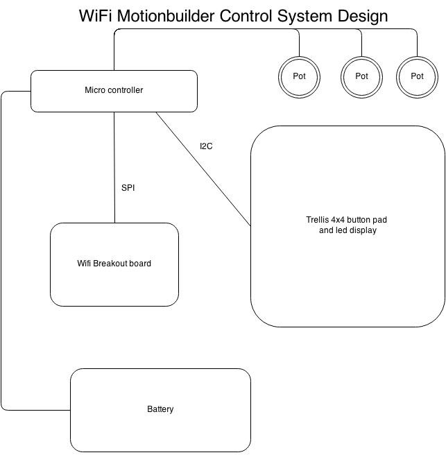
08/20/2014 at 04:56 • 0 commentsThere are only a few components. Arduino Micro, a Wifi Module connected over a spi bus, a trellis 4x4 button and led display matrix connected over i2c, and 3 potentiometers connected directly to 3 of the Arduino analog inputs. Currently I am using a USB battery pack connected to the Arduino usb for power.
![]()
WiFi Motionbuilder control
A WiFi remote control targeted for Motionbuilder, but flexible enough for other uses.