Nicholas Hill
-
August 11, Controller fixed
08/12/2017 at 02:39 • 0 commentsSo after further reading I found an forum post that said something along the lines of the left ctrl and other non character buttons could throw a monkey in the works. I changed all inputs into simple lowercase letters, and BOOM SHAKALAKA! We have buttons that work! I am noticing that the silicone button pads have too much resistance for the pi to realize a button has been pressed. Using a piece of aluminum foil worked fine though. I am hoping now its the lengths of wire going into various breadboard slots that is adding just a hair too much resistance. If not, I can always glue little hole punched circles of aluminum foil to the insides of the button rubber pad things.
-
August 10, Controller difficulties
08/11/2017 at 03:34 • 0 commentsSome difficulties arose when setting up the controller. I am trying to do them directly across the GPIO pins, because then I don't have to buy more parts. I am using RetroGame to mask the button presses as a keyboard input.
https://learn.adafruit.com/retro-gaming-with-raspberry-pi/adding-controls-software
Supposedly it should be working. It kinda half assed worked for a small fraction of time, then it stopped working. By kinda work I mean I pressed a directional button and it started madly scrolling through emulators non stop, even after the button wasn't being pressed any longer. Troubleshooting from the RetroGame forums had me check several things, was retrogame running, was a file for rules created, was the config file correctly labeled with the BCM numbers, etc. Everything checked out except for the physical test.
This is especially frustrating because the GPIO has always been a thorn in my side. (earlier test tube shaker project) With a controller the emulator runs fine. With the keyboard it also runs fine. For some reason, it runs like shit with the controller I built. I did resistance checks across the breadboard through the controller, max of 100 ish ohms on the start and select buttons mostly because I was just using a button dimple for an x y a b key instead of a proper rectangular one. The other buttons were all in the range of 10-30 ohms. It's getting late and instead of frying the damn thing I'm just gonna go on to bed. Tomorrow morning ill do resistance checks all the way through to the plug that goes on the GPIO pins, after that I'm really not sure what to attack next.If it shows a similar low resistance, I guess I'll go on the forums and look for help again. I tried looking today for a program that could show me a readout of what was going on with all the pins on the pi side, just so I could tell if the inputs were even being received or not. Would be useful.
If this controller issue brings this project to a stop until I order a teensy, Ill probably start focusing on the audio side of things until something comes from troubleshooting. Here's the controller setup as it stands right now. The cable mismatch on the A button has already been corrected.
![]()
-
August 10, Possible for a desktop config to remain?
08/10/2017 at 15:02 • 0 commentsSo the wife and I really enjoy playing games together, and there are some really good multi-player console games in the retropie library. I was wondering this morning if there would be a configuration possible where I could still use the game boy dmg as a portable, with a conversion process to still be able to easily plug in to a television for multi-player events? Thinking the best way right now would be to hide the ports needed behind a hollow compartment where the game boy games go. A couple of neodymium magnets could hold the game in place while allowing ports to be opened up that could be plugged into easily. This requires that the monitor and pi be able to fit in the case sandwiched, with enough room for ports. I would need at least one USB port, the HDMI, and the USB power in to be able to do this, with an added cutoff function for the battery pack when the pi is plugged in to the micro USB power source.
I could manage an auto kill for the battery pack with transistor gating, with the positive voltage across the transistor from the micro USB line causing current to not be able to flow from the battery pack, but I would feel a lot more confident with a mechanical cutoff switch. Possible one that mechanically blocks a port when in one position and only allows the battery to supply power when the port is closed off to basically dummy proof it. Only need one failure to fry the board. I'll have to think more on this and the configuration of ports. I could probably desolder the micro USB , but I don't believe I would have as much luck with the HDMI port. Ill have to look into how I can fit the Pi into the casing too. If i can fit it in sideways, that would be best because the HDMI connection is centered almost on the board, which would be easier to arrange for the game cartridge to cover. It would probably have to be raised off the shell bed as well to allow enough room to plug in. I can always glue some small wood bits on to mount the Pi onto. I need to find a way to isolate it from the monitor backing as well to prevent shorts. I could maybe use the magnets holding the cartridge in place to control a reed switch for a failsafe? Or have the edge of the cartridge push the switch down, enabling the battery supply. I feel the reed switch would be prone to killing power accidentally with shaking or impacts so let's just toss that idea out now while we're still ahead.
I really like now that I got a small video driver board with this screen because even attached to the monitor the whole thing is still pretty slim. Added to the fact that its so tightly sealed to the screen that I am worried about circuit damage with the amount of force I would have to use to remove it I really don't want to chance it. I'm thinking that a manual switch that the cartridge forces to be in one position when in the game boy alongside a kill switch in the side of the slot for the cartridge that is only closed when a cartridge is pushing against it to enable the battery, and then on top of that the usual power switch on the game boy in line with battery power should be sufficient to prevent one power source from being activated while another has the capability to be present. I'll mock up a circuit diagram later because I haven't gotten to wiring the power sources with the power-boost 500 basic and lipo charger circuit yet. One thing at a time.
-
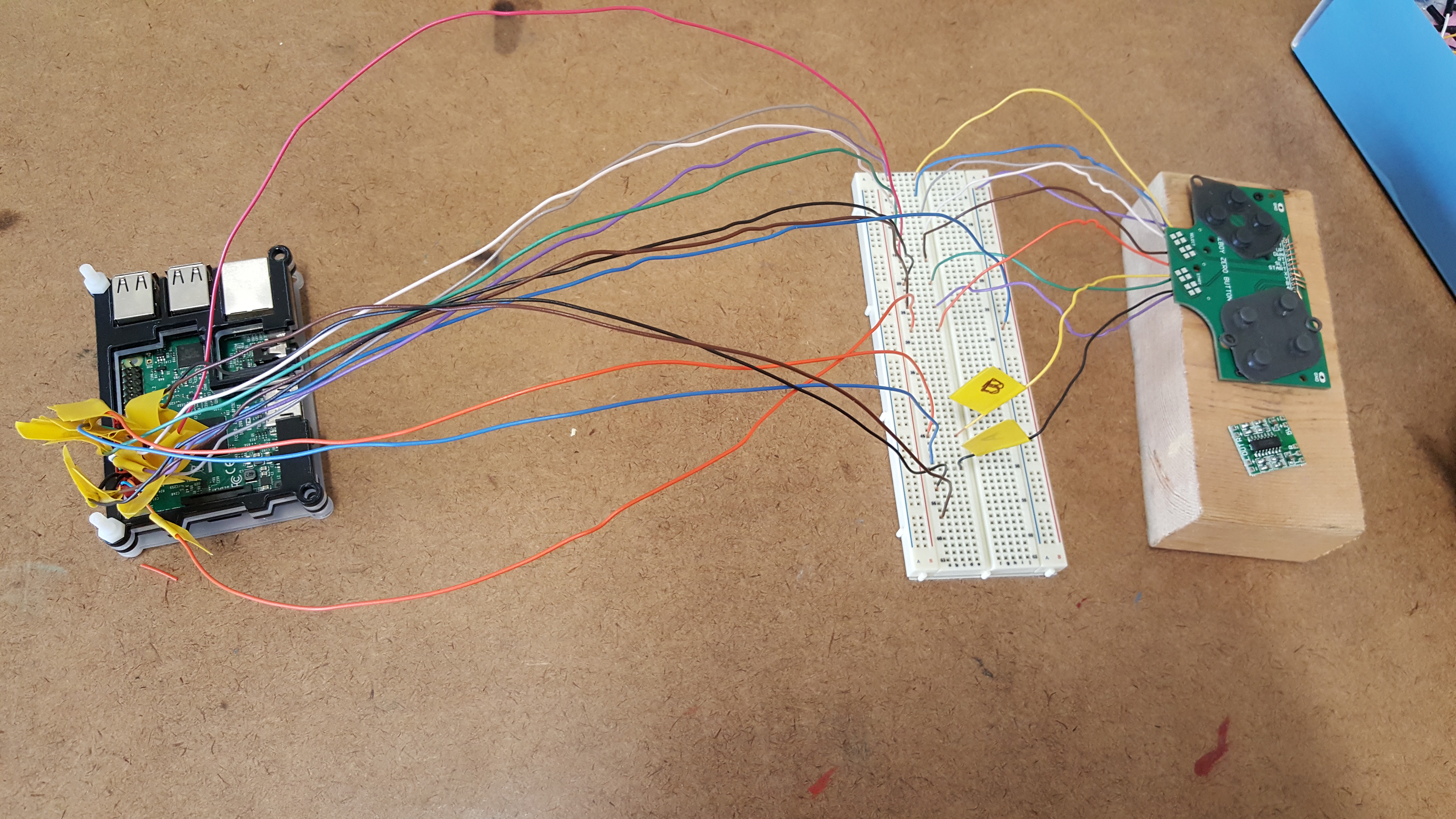
August 9, Corrected Controller wiring
08/09/2017 at 23:22 • 0 commentsClipped the cabling from an old Fire-Wire port for a PC, and used the connectors to attach to the Pi. Two connectors and some soldering later I have a testable breadboard circuit for trying to map controller inputs to retropie.
![]()
-
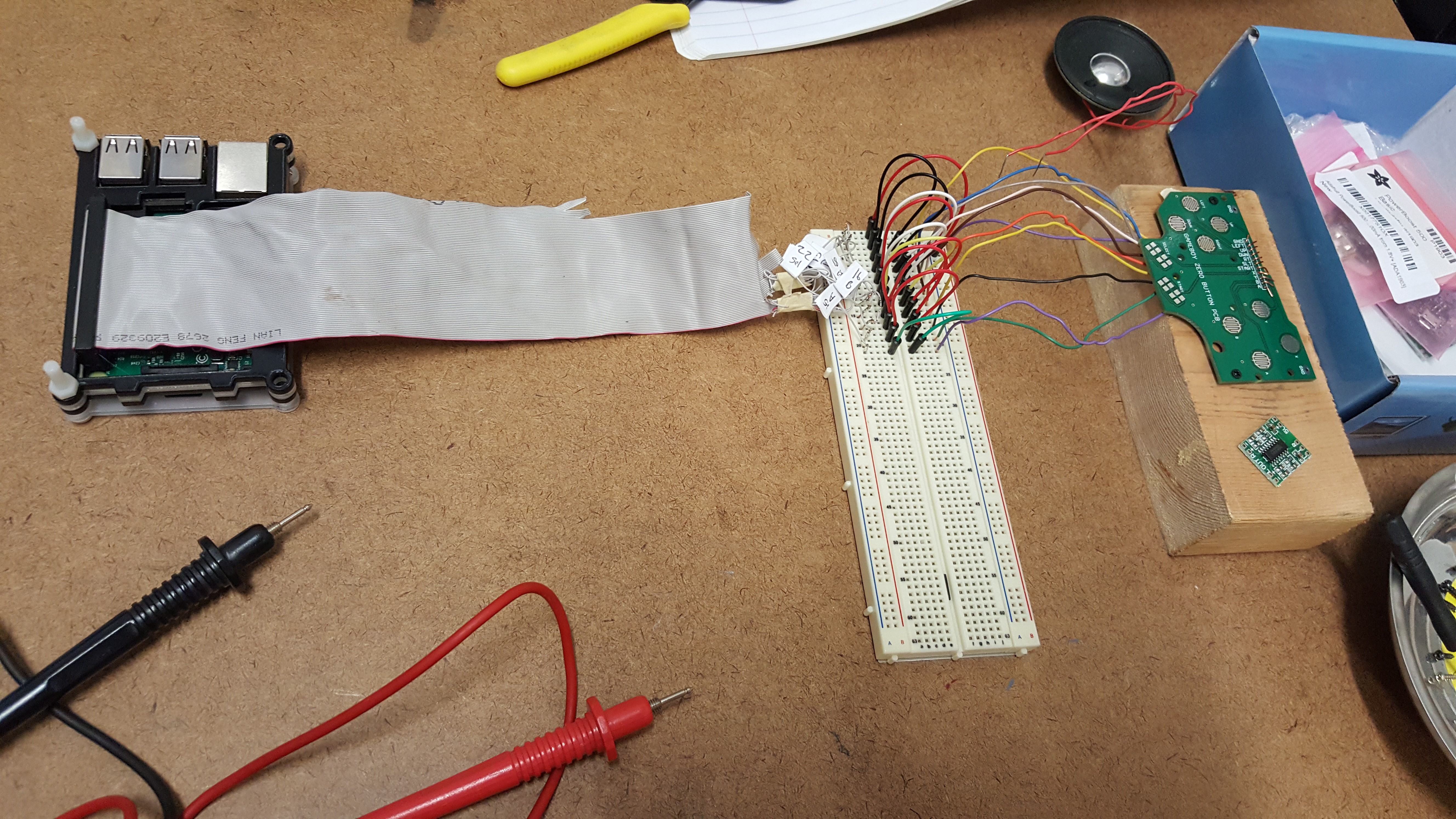
August 8-9, Controller mistakes
08/09/2017 at 18:33 • 0 commentsTried making a ribbon cable from an old IDE ribbon cable because I had a lot of them laying around the house and I'm pretty tight for cash with college and all. Turns out apparently there is a common ground shared across multiple pins. So much for assuming it was a one to one connection from one pin to the end of the cable. Tried wiring it and kept getting button presses on a lot of the leads when testing for resistance checks. Disconnected all the parts and tried again with a single component at a time, and that's when I discovered the shared ground on the IDE cable. Glad I discovered this BEFORE I tried input tests with a powered on Pi. Probably would of accidentally sent voltage across random pins. Looking at a breadboard GPIO adapter and ribbon cables for pi that are straight through on ebay, only about three dollars but I'll have to wait about a month for arrival. In the meantime I can use modified connectors from an old fire-wire adapter from when I built PCs back in the day. If I drill out the dummy plug I can make these work to continue work while I scrounge up three dollars and wait for shipping. Lost about two hours of work time with this IDE fiasco, but it could have been much worse if I had plugged it in for a live test and wrecked my Pi, so there's some positives in this mistake.
![]()
-
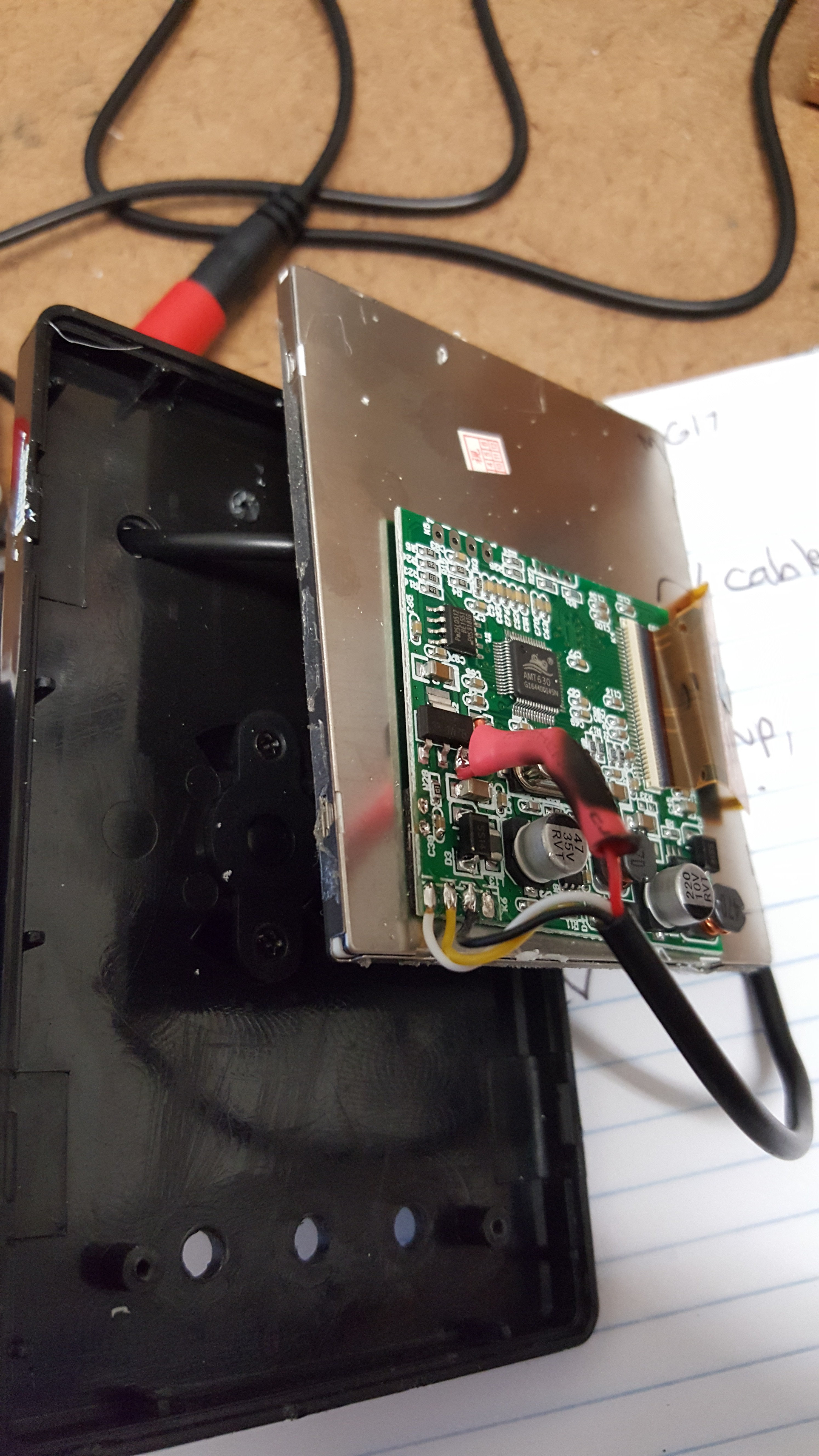
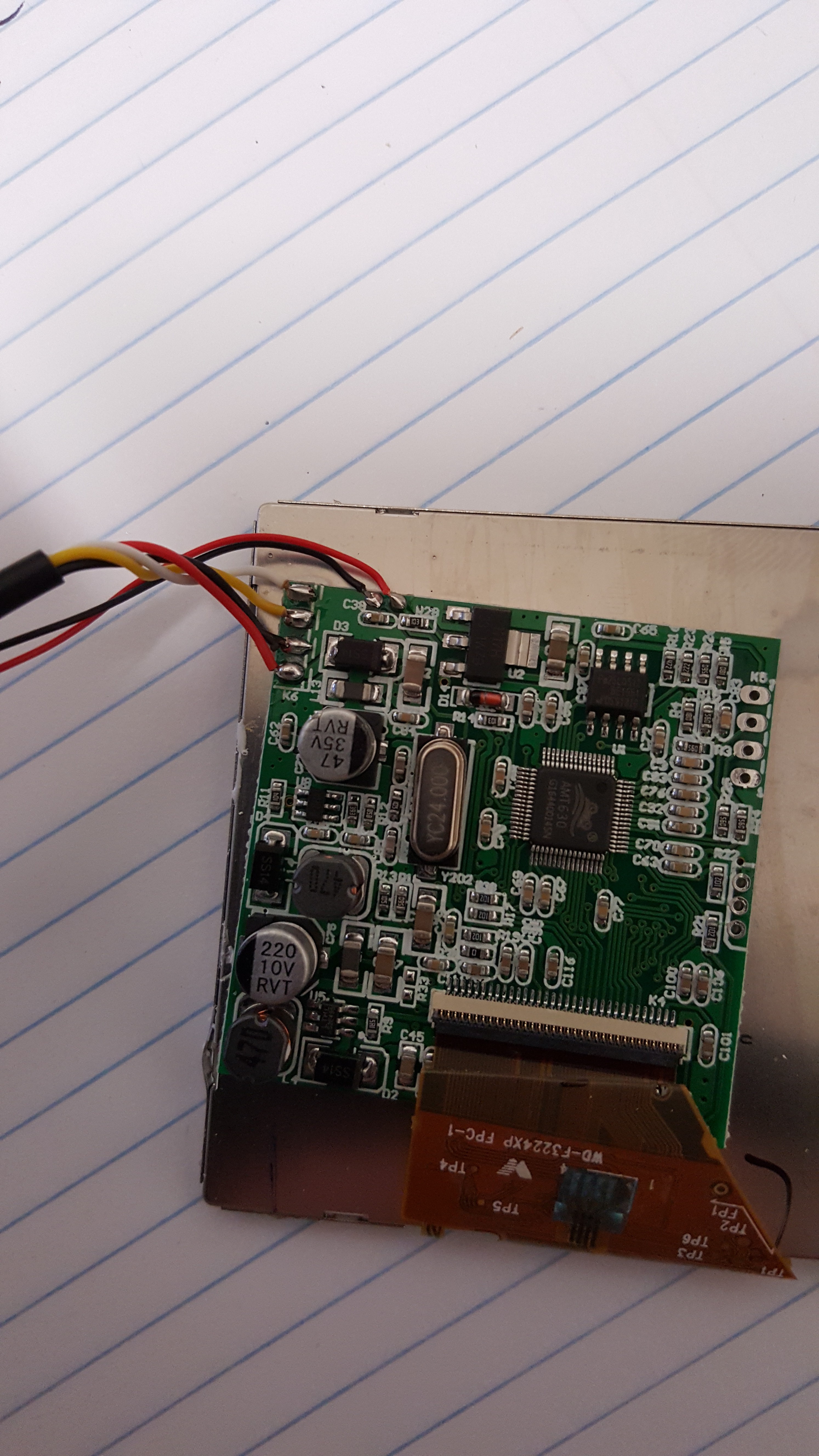
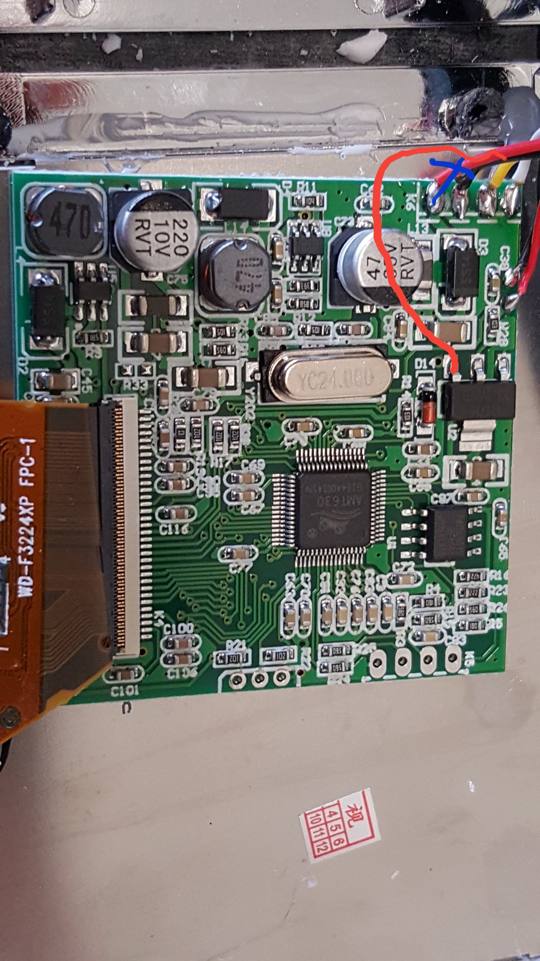
August 7, Modification to monitor
08/08/2017 at 20:05 • 0 comments![]()
Unsolder red lead from video driver circuit card, solder onto the third post on the left of the voltage dropper.
Sudomod wiki has many more models of these little TFT screens and how to modify for running on 5 volts.
http://www.sudomod.com/wiki/index.php?title=GBZ_Screen
![]() Reference shot that I doodled on to show where to move the input voltage lead to
Reference shot that I doodled on to show where to move the input voltage lead to![]()
Ignore the burn marks on the heat shrink, I over heated it a little...
Immediate tests show it works fine with a 5 volt input from my desktop power supply. Pulls about a third of an amp by itself.
Cubone! (Retropie encased in Gameboy DMG shell)
Gameboy handheld form factor capable of playing all emulation up to about a Playstation 1. I've been calling it Cubone.

 Reference shot that I doodled on to show where to move the input voltage lead to