 Lutetium
Well, we've been having some good sidebar discussion here for a bit, but let's kick it off officially and welcome Bil Herd to the Hack Chat. Today we're going to learn about high-speed PCB design.
Bil, I usually ask hosts to introduce themselves to get things going, but that seems silly here. Maybe just a quick intro?
 Hi all, I do the odd video for HAD and recently did a couple about high speed PCB stuff and have another video comoing about PCBs themselves
 OK, thanks. I am just trying them out to save space as a low power FET, but they are already causing more problems than their worth.
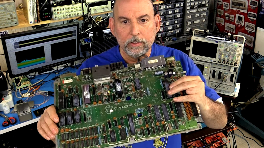
My background was that I had a backyard full of TV chassis in the '70s, never finished high school and ended up designing computers for Commodore Business Machines
![]() i actually got away with just making sure all connections are the same length and having a groundplane for 100 mhz qspi, i think anyways i guess its possible that the mcu is throttling .
i actually got away with just making sure all connections are the same length and having a groundplane for 100 mhz qspi, i think anyways i guess its possible that the mcu is throttling .
 experience is the best teacher. nice.
So first let me throw a link to the high speehttps://hackaday.com/2019/01/24/video-putting-high-speed-pcb-design-to-the-test/d Hackaday post which I will be referring to a bunch:
High speed pcb design to me, means understanding about impedance, which is the combination of the effects of capacitance and inductance.

https://hackaday.com/2019/01/24/video-putting-high-speed-pcb-design-to-the-test/
Video: Putting High Speed PCB Design To The Test
Designing circuit boards for high speed applications requires special considerations. This you already know, but what exactly do you need to do differently from common board layout? Building on where I left off discussing impedance in 2 layer Printed Circuit Board (PCB) designs, I wanted to start talking about high speed design techniques as they relate to PCBs.
When we go up in speeds it means that not only do we have to get fast signals moving around the board but also that the power supply is able to deliver current very quickly while maintain voltage regulation and stability. The two of these things are often referred to these days as Signal Integrity or SI.
A vital part of high-speed design is understanding that the PCB is an entrenched component of the design. It has differing amounts of inductance and capacitance depending on the traces and planes and it can absorb energy or even resonant.
 PCB high speed design is black magic
If we have time I can talk about differential signals such as @aerispalm just mentioned.
Hi Frank, I know you well enough to know that Hi Speed / RF design is just an extension of what you already do and know
thanks, I'm a black magic apprentice :-)
First thing I harp on is inductance and the understanding that inductance increases based on the distance to the return path, the width of the trace is minor compared to the distance
what is the "dividing line" for high speed signals? 50Mhz? 100Mhz? 10Mhz? Like when does it really start to matter?
Inductance resists a change in current, so as you might expect is bad for delivering current quickly. Capacitance resists a change in voltage so good for power supply, bad for signals.
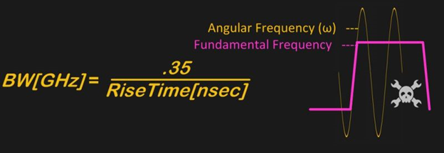
When we talk about frequency we usually mean the rising and falling edges, which typically has more hi-freq content then the fundamental signal itself, I.E. the rising edge of a 10mhz clock might have 100-200mghz of ‘radian/angular’ frequency
so speed of edges is as/more important than fundamental. Got it.
@Dave Blundell For me its when the radian frequency gets over 300 mhz, but its not a sharp edge, the faster my riser times the more careful I am
Sorry instead of sharp edge, I meant its not a certain frequency below which you can do anything and above it is considered to be hi freq
luckily with modern chips, you can set the slew rate of IOs, so that it doesn't get too high
Here is what I mean by radian freq
so adding a couple pf of capacitance to high-ish lines close coupled is a way to slow down edges and not have to worry about high speed design?
Lol... yes, don't court problems when you don't need to.
as muhc?
A cap coould cause most of the signal to be reflected if it creates an incongruence, I.e. a sudden change in the impedance of the trace.
![]() So for hi speed it is more important to have small distance between PCB layers (signal and its return plane) than paying attention to the width of the signal trace itself ?
So for hi speed it is more important to have small distance between PCB layers (signal and its return plane) than paying attention to the width of the signal trace itself ?
![]() ooh @Bil Herd that angular vs fundamental freq diagram is great. I learned something already :)
ooh @Bil Herd that angular vs fundamental freq diagram is great. I learned something already :)
First lets talk about how signals propogate, hint at the frequencies I am talking about its NOT electrons
I think adding capacitors is not good, isn't the usual practice a source termination series resistor?
@MatYay remind me about thinkness in a sec
The high speed component is an EM wave! No mass
 Series resistors near the driving pin have usually been my go-to solution. Curious if there are better ways?
EM = electromagnetic... as in Maxwell
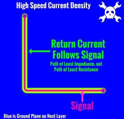
At high freq the current follows the path of least impedance, not least resistance!
![]() Mr. Applied Science did a good video series on impedance:
Mr. Applied Science did a good video series on impedance:
In the example above a DC current flow would go diagonally, but at 500mhz it will follow the trace in both directions
Yes. A transmission line works by creating a consistent impedance, such as 50 ohms or 100-120 ohms. Impedance is the combination of the capacitance (XC or capacitive reactance) and inductance (XL or inductive reactance) plus any regular-ole-resistance that is present.
So we not only want low impedance but we want a smooth consisten ride for the signal as it goes snapping down the trace.
consistent
what happens if there is no ground plane below the signal trace?
 it's an inductor!
Thing of a wave flowing through water in a trough and suddenly the trough gets smaller, you will see the part of the wave that didn't fit into the smaller trough get reflected back since it has no-where else to goa
think
Hi Ted! Yes a straight out inductor. A example of a bad situation is shown here:

And inductors resist a change in current. Inductance can be hHUGE without a nearby return path
Here is an example of too much inductance at even low frequencies:
Why would that return path be the path of least impedance?

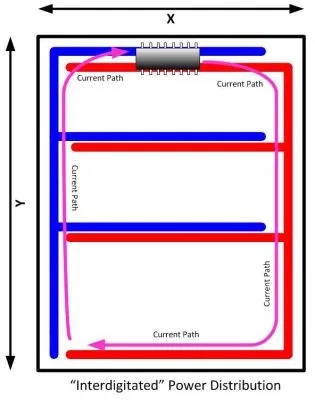
Interdigitated Power Distribution
Interdigitated power distribution results in a larger area and higher inductance.
Just because there's "nothing in the way"?
Crap, image isn't pasting, give me a sec (I hate technology)
https://hackaday.com/wp-content/uploads/2018/09/interdigitated2-e1537281708645.jpg
Dan, I cant past anymore, I have to upload.
Yeah, same thing happened to me. Odd.
are blue/red top/bottom tin that pic?
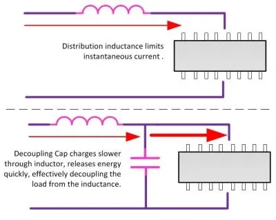
So everybody is aware of decoupleing caps, but do you know WHAT is being decoupled?
Thanks Dan, I have to sanity check myself every day and thought I failed for the day. :)
decoupling: local source of current vs. needing to pump it from elsewhere
So its the inductance, or "resistance to changes in current" that we have to decouple:
Impedance is the combination of the capacitance (XC or capacitive reactance) and inductance (XL or inductive reactance) plus any regular-ole-resistance that is present.
![]() So decoupling for the inherent inductance of the power supply
So decoupling for the inherent inductance of the power supply
power delivery from supply to point of use?
The goal is to make a smooth path, I.E. the same impedance all along the trace. Again you won't be wrong by vizualizing water creating waves opff of any discontinuities
So enter the concept of a transmission line: A transmission line works by creating a consistent impedance, such as 50 ohms or 100-120 ohms.
What that means is we live with the inductance after we have done everything we can to minimize it, and then we combine it with capacitance
to yield a value, often 50 ohms
We usually use the PCB itself to supply the capacitance!
 @Ted Yapo pardon my newb, but why would the signal with no ground plane underneath act like an inductor?
![]() The capacitance between the signal plane and the ground plane?
The capacitance between the signal plane and the ground plane?
We take the dielectric constant of teh PCB, yes dielectric as in whats in a capacitor, and then calculate the thickness of the layer and the width of the race to come up with the value we want
@siddacious it's just a wire, in the absence of anything to "capacitate" against, that's an inductor
Ted, chime in if you have something about impedance and then PCB as this is important concept
Our biggest tool for setting the impedance of a trace is to space it away from a reference (ground) plane by a consistent amount and use the PCB material as a dielectric, I.E. we make a capacitor. Once we set the distance between plane and signal and we know the dielectric constant for PCB ( approx. 4 for FR4) we calculate the tracewidth to create the right amount of cap.
@Ted Yapo ah, ok. That makes sense well enough, thanks
![]() i.e. black magic
i.e. black magic
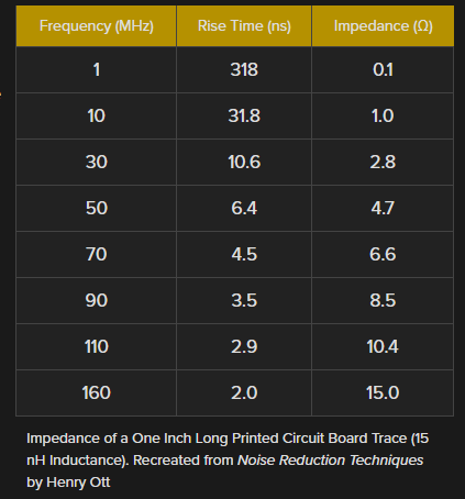
So speaking of inductance, here is a chart
15 ohms!!!! ACK
![]() [re: previous posted picture--sorry I'm slow] I get the intuition of a 'fast, local' source of current supplied by a decoupling cap. That LC diagram also looks like a lowpass filter--is that another useful way to think about it--filtering out HF noise on the powerline?
[re: previous posted picture--sorry I'm slow] I get the intuition of a 'fast, local' source of current supplied by a decoupling cap. That LC diagram also looks like a lowpass filter--is that another useful way to think about it--filtering out HF noise on the powerline?
yeah, and check out those rise times
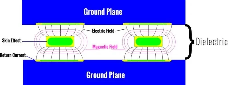
![]() The trace is just a single trace or is it over a plane ?
The trace is just a single trace or is it over a plane ?
So rule one, smooth impedance when possible, rule two,: match the impedance of the trace to the driver
but which frequency do we use to calculate the resistance? the capacitor would be 50 ohm just at one frequency
@MatYay For controlled impedance and minimal inductance there is always a ground plane for what I am talking about
so "controlled impedance" in the context of PCB manufacturing means that the dialectric constant of the substrate and thickness are more closely controlled in order to be able to achieve better tolerances?
![]() ok, thx
ok, thx
![]() Not getting this picture. The signal traces are between 2 ground planes?
Not getting this picture. The signal traces are between 2 ground planes?
@Frank Buss the awesome thing about transmission lines is that they're the same impedance at all frequencies (give or take)
@Dave Blundell Well first its the freqency based on the rise time of yoru chips. As someone noted,, FPGAs and other chips can have their outputs slowed down just to not make trouble if really fast is not needed
I'm wondering what the "checkbox" at the board house buys you?
I showed a trace with a groun above and below, sorry, let me find one for a single ground plane
most 32 bit microcontrollers also have slew rate limit as an optional feature on their gpio pins

Discussions
Become a Hackaday.io Member
Create an account to leave a comment. Already have an account? Log In.