 zakqwy
I engaged in some serious whiteboard tangenting last night on the subject of artificial muscles. Keep reading if you're bored as hell; this is a long-winded post.
I also took a bunch of close-up pictures, most of which ended up pretty blurry. My D40 never seems to have charged batteries and the S4 isn't the best for low-light, and the board is reflective, so... try to follow along? I've found numbering the board as I go helps me stay organized and follow along with my thought stream after the fact, so that's how I'll proceed here too.
(1) and (2): Conventions.
No close-up needed for this one. I tried to keep the physical names of items as uppercase letters and measurements (particularly angles) in Greek, but I don't think I maintained that discipline 100%. In any case, the numbers with the red circles around them designate intended read order.
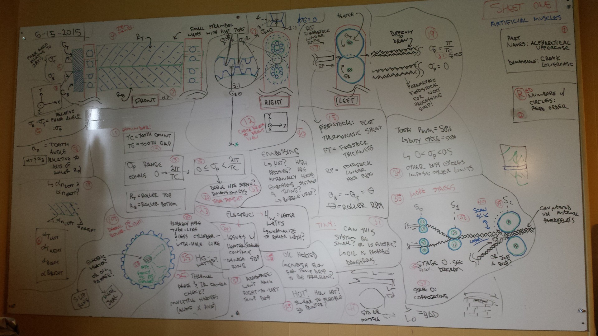
(3): Coordinates.
I made Front, Right, and Left detail drawings of the manufacturing setup; in order to speak somewhat intelligently about things like movement and rotation direction, I tried to standardize axes early:
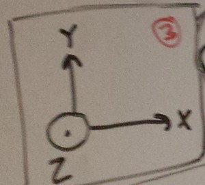
(4), (5), and (7): Front View of Stage Zero.
So what's the idea? Heated embossing and continuous fusing of flexible thermoplastics. It's not a subject I know anything about, so reading up on things like web processing, embossing, and the like will be pretty important. This drawing shows the last view a sheet of raw material sees before getting squishified:
A bit of nomenclature (which I started to do in LaTeX, but that shit takes too long): R (T and B) are the top and bottom rollers; G (T and B) are the top and bottom gears; sigma (T and B) are the phase angles of the gears relative to an arbitrary line (in this case the Z-axis--this is really only used to calculate relative phase angle between the two gears); and alpha is the roller tooth pitch relative to the X axis. I spent a lot of time scratching my head and trying to figure out how to define everything parametrically, which starts using up a lot of letters really fast and gets a bit confusing.
The rollers themselves are heated, either via internal oil passageways or integral electric elements. I think one could produce passable (if quite rough) prototypes out of rapid prototyped stainless steel; I gave this a bit more thought later on and started getting concerned about raw material sticking to the rollers, so some complicated indexed lathe-based machining method might be a better choice to maintain a passable surface finish.
Roller tooth geometry--I'll get into it in more detail later. Suffice it to say that the cross hatches and lines shown in this picture aren't terribly accurate, but they're easy to draw. The rollers are mirror images of each other, rather like the two helical gears.
Boring stuff: Red bars are supports, and they have internal ball bearings. I didn't include a huge amount of detail here--they'd probably be press-fit from one side, but I think standard radial bearings will do the trick. since the axial load should be low. I might need something that can handle a high temperature, depending on the clearance between the rollers and the supports. I think some mechanism to adjust the spacing between the two shafts will be useful too--more details on that later, I suppose. I guess that would be a pain with the helical gear setup though.
TL;DR: The rollers turn in opposite directions at the same speed; they're precisely synced relative to each other, separated by a controlled phase angle; and the rollers themselves are not fully meshed (details on that too... later).
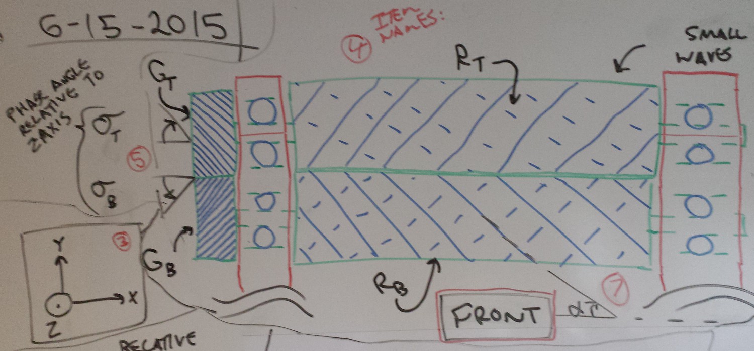
(6), (8), (9), and (10): Roller Phase and Tooth Angle.
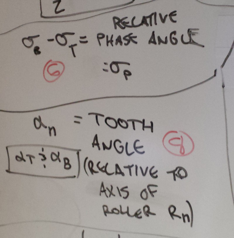
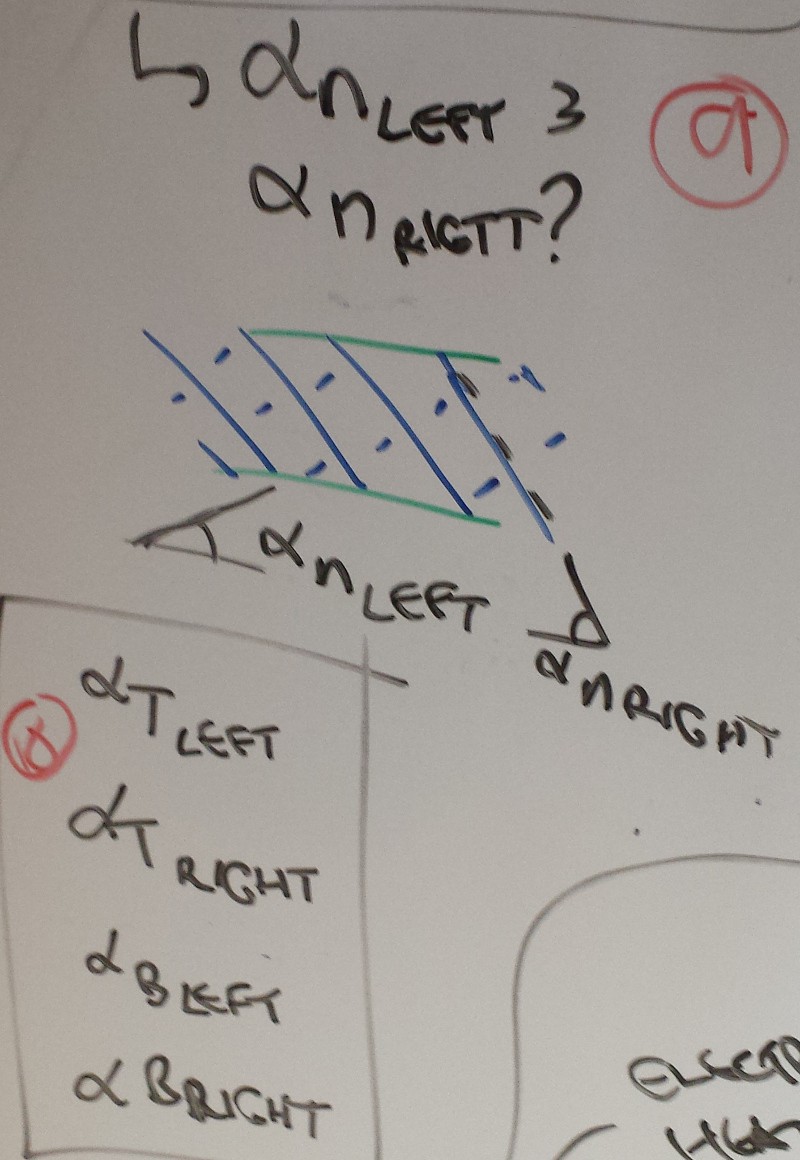
Remember what I said about tangenting? And trying to make everything parametric? In any case, I wanted to track the pitch of each roller (alpha)... then I wanted to track the pitch of each roller twice (i.e. the teeth can be laid out in a 'rhomboidal' [alpha right == alpha left] or a 'parallelogram' [alpha right != alpha left] configuration)... then I decided to differentiate between the top and bottom rollers, hence (10). Looking back on this, it doesn't make sense to keep track of the rollers separately since they need to intersect consistently.
Okay, forget about alpha--not something I really get back into at this point. Ultimately if alpha is greater than pi/4 [BOOM RADIANS MOM WOULD BE PROUD] the longitudinal aspect ratio of the indentations will be greater than 1, and the muscle should contract when the cavities are pressurized. But that is a bit down the road--this is just Stage Zero!
Sigma is more relevant--this is the phase angle between the gears. In this case, sigma (P) is just the difference between the two offsets; maybe I should call that 'delta sigma' or something. It's not normalized to anything at this point, but it's the first step in planning how much the roller teeth overlap. Make sense?
(11) and (14): More dimensions.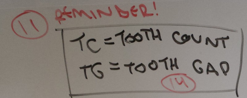
Pretty straightforward. The gap between the closest point of the two rollers is TG, or Tooth Gap. The number of teeth per roller is TC, or Tooth Count. Yeah, I'm thinking about the rollers in 2 dimensions right now--makes it easier, I suppose. In reality, I should probably be thinking about rollers in terms of 'flights' and stuff like that.
(12) and (13): Right View of Stage Zero.
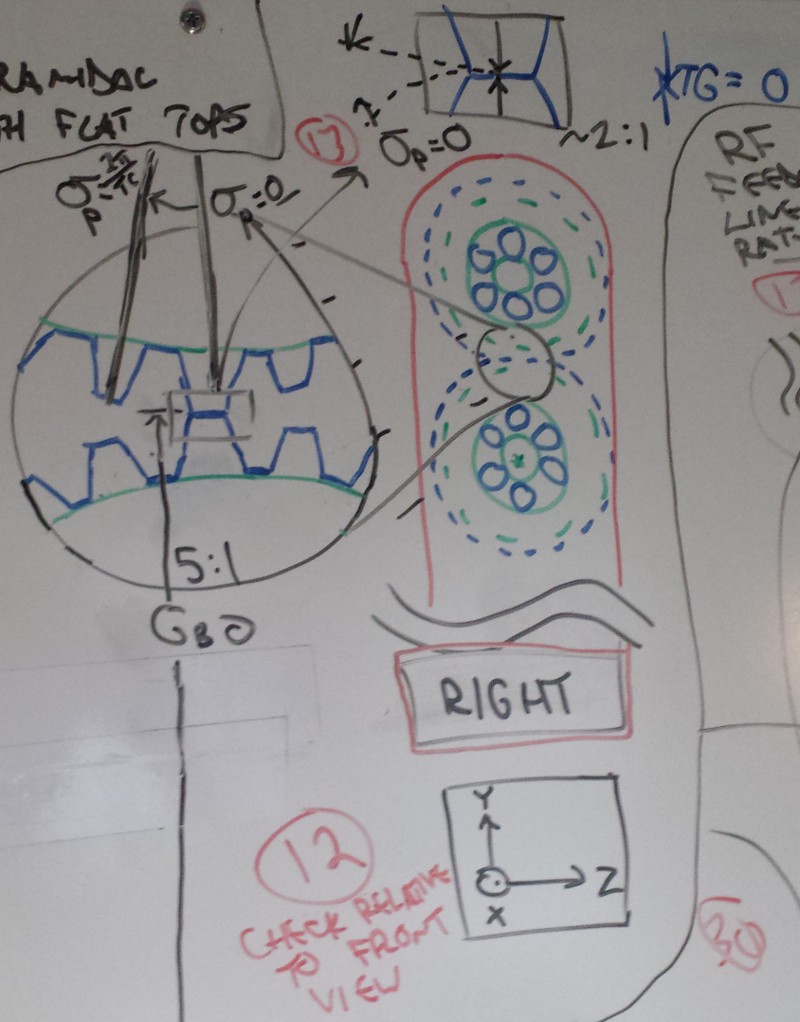
Okay, more terminology here. You can see sigma in full effect; the lines on the top roller assume that the bottom stays stationary and the top moves. Essentially, sigma only matters in the space between zero (fully overlapping) and 2*pi / TC (360 degrees divided by tooth count), where the teeth once again overlap. Otherwise it starts repeating as teeth repeat.
I didn't use good drawing practices here (or anywhere... ); the closeup of the teeth is supposed to be a 5:1 blowup of the intersection shown between the two rollers. In any case, you can see in the closeup that the teeth barely touch (TG = 0), and they are in perfect phase.
(15) and (16): Bounding Sigma.
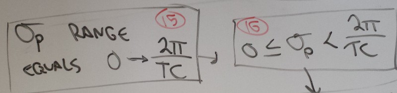 Pretty straightforward--as discussed earlier, Sigma only makes sense across the range shown after which it starts repeating (assuming the rollers are the same size and have the same number of teeth and the same.. etc.)
(17), (19), and (32 [!!]): Left View of Stage Zero.
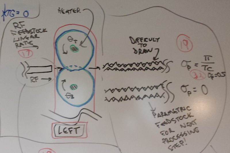
Time for some more 'system level clarification'. Right below (17) you can see the raw feedstock--it's a flexible thermoplastic of some sort. Feed it in with the rollers heated to the right degree and rotating at the right rate, and you get various profiles out the back end. (32) is worth bringing up here; I want to normalize sigma (p) so it exists between 0 and 1. 0 means the teeth are lined up perfectly; 0.5 means they're out of phase by 90 degrees, producing a sawtooth pattern. The background bumps (little triangles) show that alpha is greater than zero, so this produces a sort of checkerboard pattern of embossed shapes. You can also see the shaded heaters inside the rollers. RF is the incoming material feed rate, and theta (T and B, although they should be equal) is the rotation rate of the rollers.
(18) More definitions.
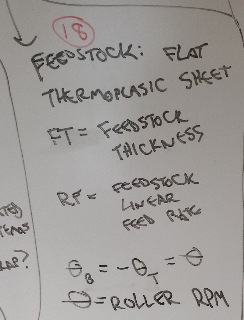
... as stated above. Adds in feedstock thickness (FT) and clarifies that theta should be a single value.
(19b), (20), and (22): Heat the rollers.
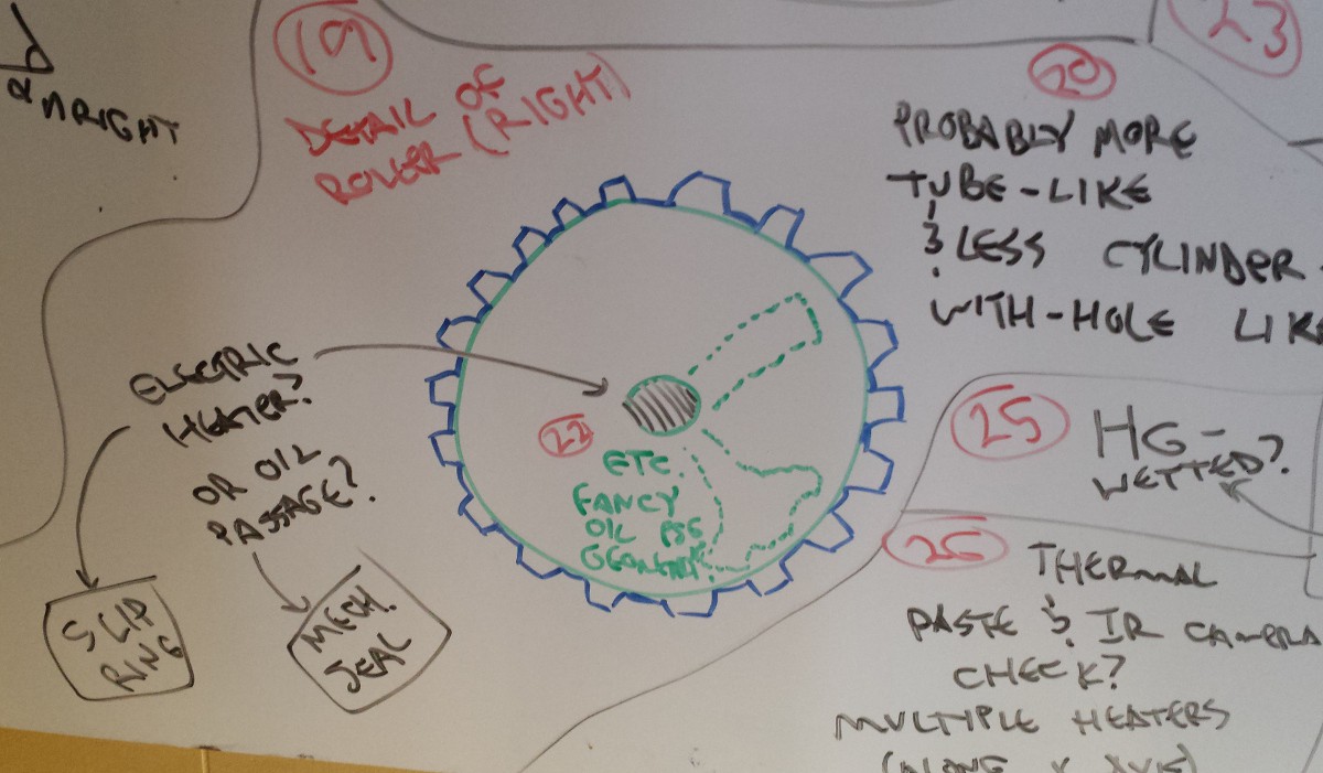
Looks like I used (19) twice--so it goes.
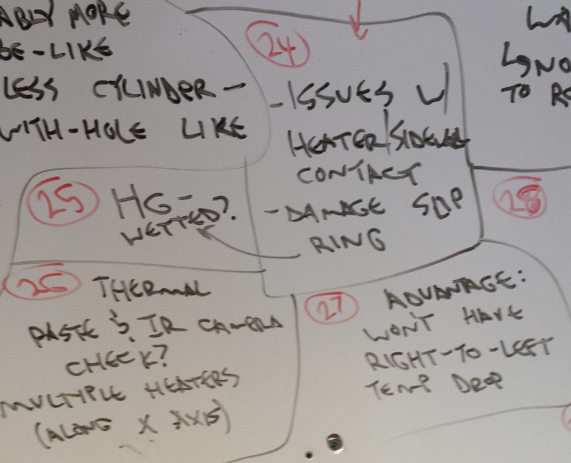
Cross section of one roller, including an important comment under (20): the rollers, in order to increase heat transfer to the feedstock, will be more tube-like and less cylinder-with-hole-like. This will probably be a tradeoff between processing speed and roller strength (and a bunch of other stuff). In any case, two options: electric heat (which requires a slip ring to transmit power) and oil heat (which requires a mechanical seal). In (22) I included a few concepts for internal oil passages; again, if the rollers are rapid prototyped (SLS?), this should be pretty straightforward.
(21) and (33): Back to sigma: make it dimensionless/normalized/like strain.
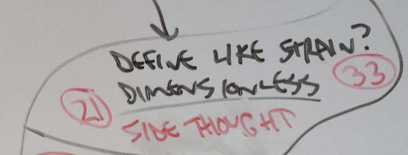
I wrote 'side thought' in red because I needed to Move On From This Tangent. In any case, dividing sigma (P) by its maximum useful value (2*pi / TC) should normalize it from 0 to 1 so it's easier to understand. It is now sigma, with no (p).
(23), (24), (25), (26), (27), (28), and (29): Heater comparison.
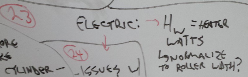
That part of the board is confusing disaster. Comparing oil and electric internal heat for the rollers:
- Electric (where H (w) is heater watts)
- Issues with heater/internal sidewall contact; would need to use heat transfer compound of some kind. Might still produce hot and cold points that would need to be evaluated in real life, potentially with a thermal camera.
- Could use multiple heaters to avoid hot spots (so I could control the roller temperature along the X axis), but this would add a lot of complication.
- Need to transmit high current through the rollers; I've got a decent slip ring that I didn't use for #GimbalBot, but I also don't want to damage it with heat from the heating elements. Maybe use a mercury-wetted slip ring? Gross.
- If I can figure out the contact area/hot spot issue, I wouldn't have issues with the temperature dropping along the X-axis of the rollers. That is good.
- Large. Bulky.
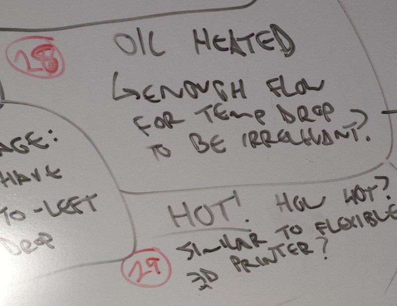
- Oil
- Gross. Hot oil, seriously? Thermoplastics don't exactly melt at room temperature. I'd need _really hot oil_. Therminol? How do I heat and control it? Sounds expensive and dangerous.
- As with a heat exchanger, will my oil temperature drop significantly if it's only flowing in one direction? What's the max allowable temperature droop across the rollers, and will it actually be a problem?
- Mechanical seals for the oil--I suppose it'll be at pretty low temperature, but I still need it to fill the passageways on the roller and connect to a stationary reservoir and heater. Sounds tough with the high temperatures involved.
- Dangerous. But could be quite small?
[Okay #Feedback - Hackaday.io--bulleted lists are buggy as hell, getting this to format correctly took a lot of trial and error. The usual tab/shift-tab didn't work consistently and I had to rewrite this a few times.]
(29) brings up an important question--how hot will everything be? I'm guessing T[material] < T[roller surface] < T[roller heater]--am I in the 500+ F range yet? Sounds sketchy and smelly and full of annoying things like failing bearings and changing dimensions. Might be worth trying to find a low temperature polymer for starters. Or Play-Dough with FDM rollers for the first tests.
(30): Finally time to think about existing technology.
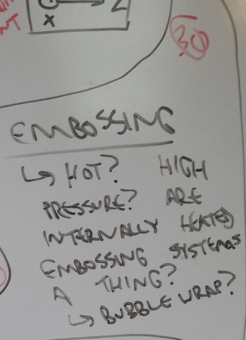
Embossing is a thing. Is it done at high temperatures in a commercial setting? Is that how they make the cool squishy inserts that go in shoe soles to make them bouncy? What's the pressure like? I've been through a few hot and cold rolling mills; the pressure on the roller frame is immense, and the rollers are ridiculously tough. What about heated rollers, do people do that?
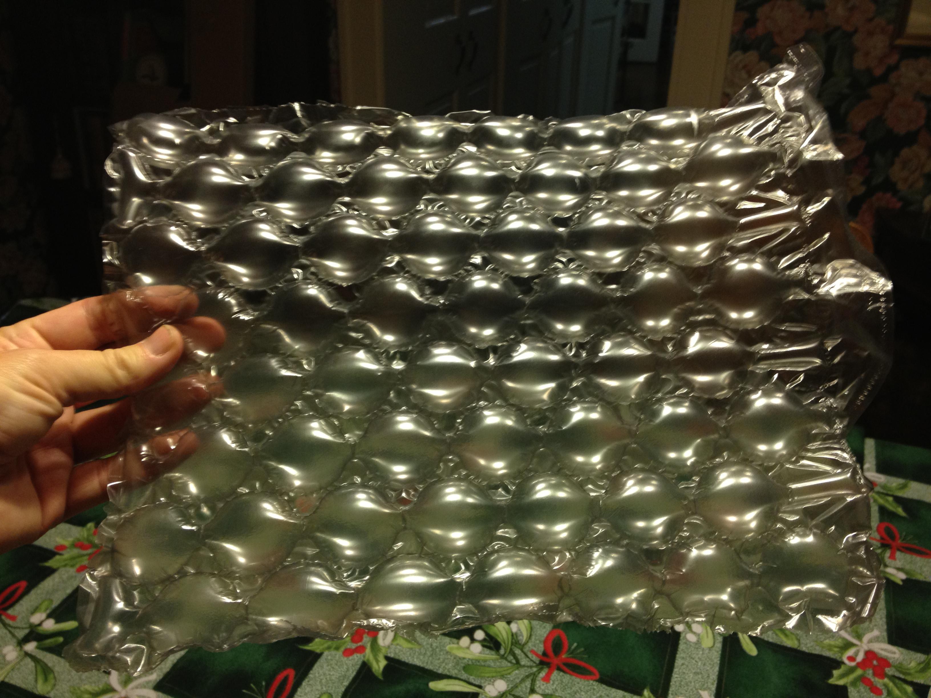
How do they make bubble wrap? Am I just trying to re-invent bubble wrap?
(this whiteboard expedition started while playing with bubble wrap, for what it's worth).
(31) Size constraints?
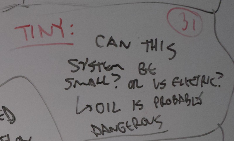
Small is good. Oil would be easier to miniaturize, since I don't need to worry about wires. Or spendy slip rings. But... oil is probably dangerous, as noted above.
(34): Tooth duty cycle vs sigma.
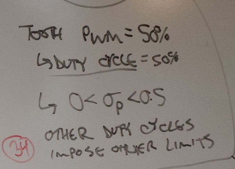
Duty cycle/PWM? How much of a roller tooth is high and how much is low, that's all. So if it's 50:50, then sigma (drop the 'p', it's normalized) should be between 0 and 0.5 to prevent overlap.
(35+): More stages make shit more interesting!
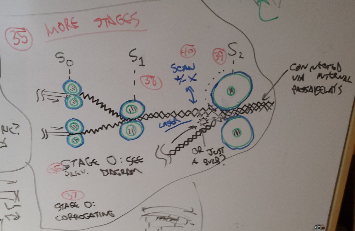
So if you've made it this far (I'm sorry), this is the real meat and potatoes. Coincidentally I just had potatoes, although it was a vegetarian dish so no meat. In any case, the previous 34 rambling thoughts covered Stage Zero; that's just preparing the raw thermoplastic. Since these images are a Left view and in two dimensions (so something like a Left section view at some Y/Z plane), I call Stage Zero corrugating in (37). Then, in Stage 1 (S1), another heated roller setup fuses the two individual sheets together at certain points. Where?
Well, that's complicated. If Stage Zero has a sigma value of 0.5 and S1 has a sigma value of 0, in two dimensions (and with a 50% duty cycle and an appropriate S1 TG and other stuff like that), this will produce a continuous stream of zigzagged pockets. With the right tooth geometry, I think you could create something like modern bubblewrap; you know, the fascinating but infuriating kind where all the internal cavities on a sheet are connected so it's impossible to pop:
So that's the idea. The size of the interconnects, the area of the squished parts, the profile of the domes, everything--it's all controlled by the tooth geometry, angle, phase, etc etc etc. I think another whiteboard session that only looks at tooth geometry and resulting materials would be good, but it's really tough to draw 3D continuous sheets in a precise and understandable way.
Then.. in (40) and (39) and so forth--S2 (and S3, S4, etc) start layering these together to create additional internal passages, all of which are networked together and connected in such a way that you can modulate the pressure inside all of them via a single connection point. Or maybe a few connection points to improve durability if one section breaks.
More 2D inspiration: the army's cool never-flat rubber tires:
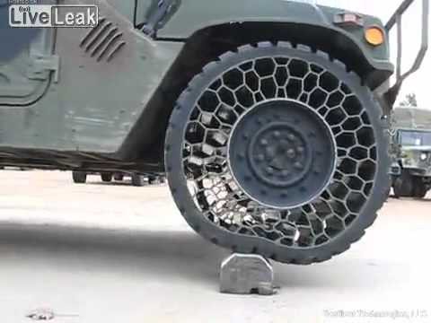
I'm guessing this is all extruded through a ridiculous die of some kind, but I suppose it could be molded a sheet and rolled around a wheel. In any case--you can see the hexagons changing geometry as they get squished. Same concept, but if the hexagons were stretched and you applied internal pressure, they'd get 'rounder'.
Another thing to consider: Stage 0 and Stage 1 can pretty much squeeze the feedstock as much as they want while heating it to get the material to fuse together. Stage 2 can't do that; you'd end up distorting the internal cavities, and the Stage 2 rollers (and beyond) shouldn't be heated either. Hence in the picture--a radiant heat source in between the feeds running into Stage 2. Maybe a fast scanning laser of some kind? Or a long halogen light? I dunno, something to heat up the vertices of the Stage 1 output stock so it sticks together under moderate Stage 2 pressure.
Okay, time to think about problems.
Off the top of my head:
- Getting everything started. More stages = more feedstock to get in the right place. Also, when the first material hits the rollers they'll be crazy hot, and might just melt the material before it goes through. And what about material drooping between stages? What if it's so hot in the area that stuff just deforms? Might need cooling fans?
- General control. Even if you went 'constant power' on the heaters and controlled feed rates and so forth instead, you'd still need crazy good control over the speed of each roller. Could microstepping accomplish this? Phase angle between teeth and synchronization between stages is super important!
- Thermal stuff in general. I talked about this above, but parts of this system (specifically the internals of the rollers) might need to be extremely hot. Not hot rolling hot, but still hot. Hot enough to require special bearings, room for thermal expansion, expensive greases, and generally be dangerous and stinky.
- Getting the feedstock to stick at Stage 2 and beyond. What if I can't keep the intersecting bits hot enough? Or maybe they sorta stick together but then burst apart when I apply pressure to test the muscles? Can a radiant heating system get the right parts melty enough without damaging the substrate?
- Sticking. Do the rollers need to be smooth? I think the tooling needs to be mirror polished--that's what a lot of injection molding tooling is. I don't want a pitted surface that gets loaded up with feedstock and produces a sloppy, textured result. Not a huge deal for bare cylinders, but how the hell do I rapid prototype the rollers? Is SLS (or some other technology) adequate, and if not can I polish them after the fact to a suitable degree? Or do I have to machine the rollers? Seems like I'd need at least a 4-axis setup to do this well, along with some custom cutters.
- What material do I use? Can it hold enough pressure? What kinds of alpha values or tooth angles will I need to produce an aspect ratio that actually causes a reasonable contraction under pressure?
- What problems does this actually solve? Air muscles aren't perfect, but why? Seems to me that controlling the air (and the fact that it's slow and compressible) is a bigger issue than trying to make the individual pockets small.
Okay, end of brain dump. I'm going to leave the whiteboard unerased for a few weeks to mull this over, but more than likely this won't turn into anything else. If you've got experience in embossing (or anything else that's related), I'm always up for a good constructive discussion.
Discussions
Become a Hackaday.io Member
Create an account to leave a comment. Already have an account? Log In.
Thanks for the long-winded warning :) Those buggy nested bullet lists look like a nightmare here! They would have been a lot easier in LaTeX, but I wouldn't know, I never liked the layout of latex-project.org. Maxxis has an article 'How a Tire is Made' http://www.maxxis.com/other-automotive-information/how-a-tire-is-made revealing some industrial processes and temps. The in section “Belt and Ply Calendering” mentions steam heated chrome-plated steel rollers. I always wanted to know how they make inflatable rafts, because of the flexible/durable material and seams. Far fetched: Do you think you could modify a printer hot end to make some test patterns before you take your bubble wrap fixation to full production?
Are you sure? yes | no
I've been mulling over an FDM printer modification--I think it could be possible. Think it's feasible to use a RepRap to make airtight flexible structures, using something like NinjaFlex? Maybe with some additional post-processing to seal gaps?
Are you sure? yes | no
I was thinking of a hot roller on the end melting 2 layers, but your idea is even better! I just got my first up close look at a 3D printer in action (LulzBot at SparkFun) and I can't wait to see pics of yours :)
Are you sure? yes | no
Sounds good! I'm still gathering parts but I'll put a project up once I start the build. I'm doing a RepRap TS with an E3D v6 extruder (not the Lite version).
Are you sure? yes | no
Your .Stack page a month ago on 3D printers was great. I have been looking at the E3D v6 since you first mentioned it. (I'm building an imaginary printer along with you.)
Are you sure? yes | no
If you decide to do so, I recommend the Wilson TS if for no other reason than Marty (developer of the design that runs an eBay store for parts) is fantastic to work with.
Are you sure? yes | no