 Weird Circuits
This article is about a simple transistor mixer circuit.
This device can be used for mixing audio samples that are used for make music, particularly techno. However, because the supply voltage is only 1.5 V it is very easy to saturate the output.
Step 1: Design the Circuit
The circuit was drawn via PSpice student simulation software version 9.1:
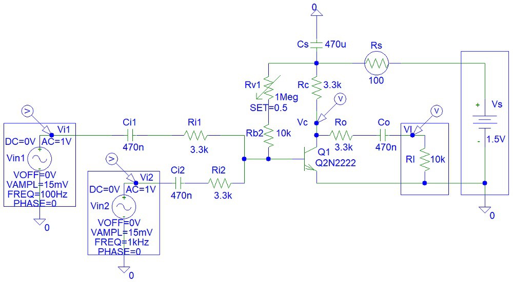
The input lower band pass frequency approximately equals to:
fil = 1 / (2*pi*Ri1*Ci1)
= 1 / (2*pi*3300 ohms*(470*10^-9 Farads))
= 102.614405604 Hz
The output lower band pass frequency approximately equals to (assuming the load is short circuit)
fol = 1 / (2*pi*(Rc+Ro)*Co)
= 1 / (2*pi*(3300 ohms+3300 ohms)*(470*10^-9 Farads))
= 1 / (2*pi*6600 ohms*(470*10^-9 Farads))
51.307202802 Hz
This frequency is a bit high. The lower band pass frequency supposed to be about 20 Hz. However, I was trying to avoid the use of electrolytic/bipolar capacitors.
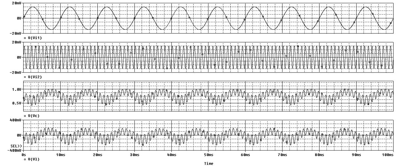
Step 2: Simulations
Simulations show that the transient response is amplified:
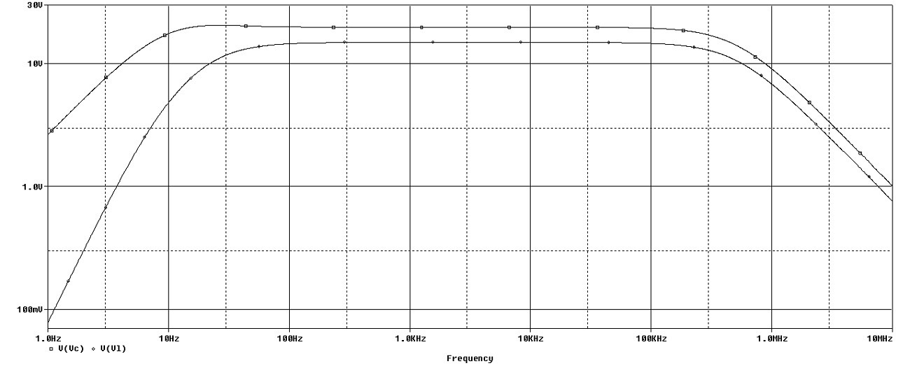
Frequency response:
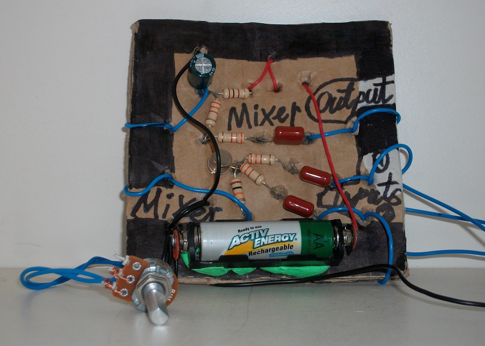
Step 3: Make the Circuit
I made the circuit on a piece of cardboard to avoid purchasing a matrix board:

Step 4: Testing
I used Instrustar USB Oscilloscope for testing.
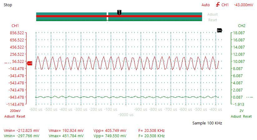
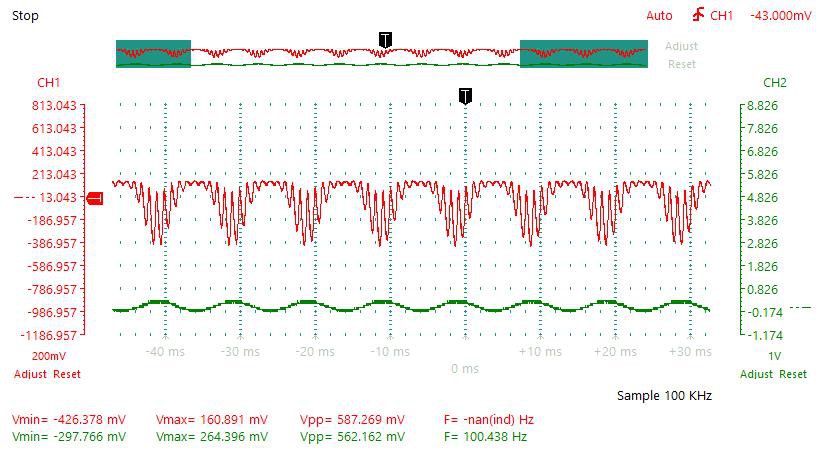
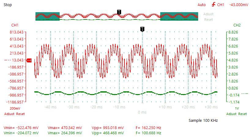
In the plots below the green signal is the input and the red signal is the output.
1 kHz Input Maximum Gain:

The gain is 810 mV / 187 mV = 4.33155080214
I placed additional resistors in series with Ri1 and Ri2 to prevent output signal saturation. Thus the actual gain is a lot higher than the calculated value of 3.44155.
Gain can be increased by reducing Ri1 and Ri2 resistors values and at the same time increasing the Ci1 and Ci2 capacitors (to prevent the rise in lower band pass frequency).
20 Hz Input:

20 kHz Input:
Distortion 1:
I varied the variable resistor to create distortion effect:

Distortion 2:
Summation:
Conclusion
This simple transistor mixer only need one 1.5 V AA or one 1.5 V AAA battery to work.
Discussions
Become a Hackaday.io Member
Create an account to leave a comment. Already have an account? Log In.