 Vladimir Aubrecht
Long time ago it all started with me trying to find new keyboard. After couple of weeks browsing through every possible manufacturer I got an idea:
"How hard it can be to build my own keyboard! It's just few buttons connected to microcontroller, I'll have it done in a month or two ..."
... 2.5 years later - it wasn't that easy 😛 Lets start from beggining.
Feel free to skip quotations as those are providing in depth view but are not critical in overal story.
Each chapter contains estimate of time I spent on it marked with ⏱ symbol. Be aware it's calendar time as I don't remember how it was in a real time. Typically I was working on it through Saturday's nights or on few evenings during the week.
Target audience
Article is covering my story of building my first hardware device - keyboard. Hoping it will give people better insight into what they are going into when starting with new project and avoid underestimating of certain things like me 😃.
So who should read this?
- People interested in a story of building first piece of hardware by software developer.
- People who has little or no experience with hardware building and they'd like to start.
- People interested in keyboards 😃
What you should NOT expect?
- In depth details
- Documentation like article.
- How to guides.
That said, feel free to contact me in case you'd like to know more or just in case you'd would interested in in-depth articles/videos going into technical details (if I'll find enough of people, I'll be happy to spend some time on it).
Background
I started a project as a software developer basically with just very little knowledge of electronics, no mechanical engeneering, no iron melting skills, etc. Mostly working in languages very far from actual hardware (like C#). What I had is some background on hardware from my university times.
That said, I started with a research to find out where to even start!
Article is mentioning some commercial services or products. I don't have any financial affiliation with them except of Saleae's Logic Analyzer.
Saleae was keen to me and provided me:This article was written as a source of information on struggles you might find on this type of project, not to promote or sell any product.
- Discount on their analyzer because I am hobyist.
- Sponsored writting of this article without any requirements on outcome of my recommendation on their product. Check their requirements here.
What is inside a keyboard?
After a quick Google search you find pictures of keyboards and typically you quickly realise, that you need these components: case, PCB, switches, keycaps.
Not only that, you can buy those things separately and there is huge variaty of them! So why the hell would I build everything from scratch, when there is an easier way ...
Well, it wasn't. I knew few things:
- I want compatibility with Cherry MX switches. Don't want to go into that river as I was happy with them and I had already plenty of things to solve.
- I can pick beautiful and functional keycaps from those on the market and knowledge building around the keycaps would be on a whole book ...
- I wanted TKL1 PCB with USB-C, Bluetooth 5 and RGB leds configurable and triggerable from computer. As far as my knowledge goes, nothing like that existed on a market at a time I started with this project. Not only it didn't exist in a combination of these features, but even each feature separately was problem - Small amount of USB-C PCBs, no Bluetooth 5 PCBs, no PCBs with configurable & trigerrable RGB LEDs and very limited amount of TKL PCBs (60% were very popular & available for some reason at that time...).
- On a case aspect, I love traditional designs Filco like designs in aluminium. I was originally fine with any aluminium design, but eventually I realised that it would be too restricting (like pre-drilled holes for LEDs which I don't support) for my PCB development about which I already knew I will need to build. That was the reason why I dropped idea of buying finished case and rather go in a direction of building it.

That simplified my keyboard building problem, I finally knew that I need to build my own PCB and a case around it.
Proof of concept
So how do I start when building PCB? Well I heard something like Arduino exists so lets go from there. I started to Google and found QMK. For those who are not familiar with it, it's an opensource firmware for keyboards.
That was just perfect as I could completely avoid programming part or at least I thought so ... 😛
Firmware
⏱ 2 months
QMK supports variaty of microcontrollers so I bought my first microcontroller, connected a switch to it, pick one of keyboards with a same microcontroller, adjusted configuration, tried it and after few nights (or a month? 😛) and microcontrollers (yep, I had to buy new one, different one) it worked. I could actually press the switch and computer was getting configured key. Hooray!! 🎉 🎉
I'd like to thank QMK community for helping me with this.
Remember I knew not much about hardware? This was that hard lesson time!I am not going provide answers on those questions, but it should give you idea of existing problems...
- What is pinout on my microcontroller?
- Why each pin has bazilion of names?
- What is USB HID and V-USB?
- Which name should I use in QMK firmware?
- Why it's sending non-senses to a computer?
- Wait, what is EEPROM? What the hell, why my EEPROM has random data instead of zeros? ...
Wiring
⏱ 1 month
It was success, but game is not over yet. Now is the time to connect rest of the switch right? No problem!
I needed 87 switches, each switch needs 2 wires, so I just need for 174 wires connected to microcontroller. Wait what? Microcontroller I had was Arduino Micro with 20 digital pins and some searching explained me, that I'll not have 174 pins on a microcontroller fitting a keyboard ... 😃
How this works is, that switches are connected in a matrix. This is something what can help you to reduce those 174 wires to 23 wires (6 rows and 17 columns). 23, that already sounds much more reasonable, but still I had only 20, so what's next?
IO Expanders were the answer for me. IO expander is a chip which allows you to add more PINs to your microcontroller. It works in a way, that you communicate with it through some protocol (I2C, SPI, ...) and it exposes you additional PINs through those interfaces. And it gets even better, you can use multiple of them! 😃
I skipped mentioning details like problems with ghosting when using matrix like connections which you can mitigate by adding diods.
Wiring and using of I2C & SPI is not so straightforward how it can look like. Especially if you don't have any experience with electronics you'll probably hit ugly problems, more on that later.
PCB
⏱ 3 week
At this point I was ready to build a PCB to get switches on a fixed position and I can finally start typing on my custom made keyboard! 😃
So I opened KiCad, created my design, uploaded it to jlcpcb and after 2 weeks package finally arrived and PCB were beautiful!
Sounds easy, he?
What is KiCad and how did I learn about it? It's a software which allows you to design your own PCB.
KiCad opens completely new chapter of problems for you, which I am not going to cover in details in this article in depth, just to give you idea of complexity:
- How to draw schematics, including importing custom made symbols.
- How to draw PCB tracks, including importing custom footprints.
- How to export Gerber files for your manufacturer.
- How to solve compatibility issues (like manufacturer can support only tracks with some minimal distance from each other, but your design can have them closer...)
- How to pick components and how to solve stocking issues?
- What are dimensions of PCB? (random for every manufacturer)
- What are dimensions for layour of keys? (nothing standardized)
- What are dimensions of sockets? Can I find footprints for KiCad? Yes.
- ...
Of course it didn't work. I just couldn't start communicating with IO expander for some reason. It took some time, but eventually I found out that there exist something what is called pull up or pull down resistor and well I was missing them in my circuit.
Simply said, you can use pull up or pull down resistor to set "default value" to undefined pin. It's either pulling voltage up or down in case non of the pins is driving the line.
I used MCP23017 IO Expander. It communicates through I2C protocol which requires in total 4 wires - VCC, GND, SDA, CLK. SDA a CLK needs pull up resistors.
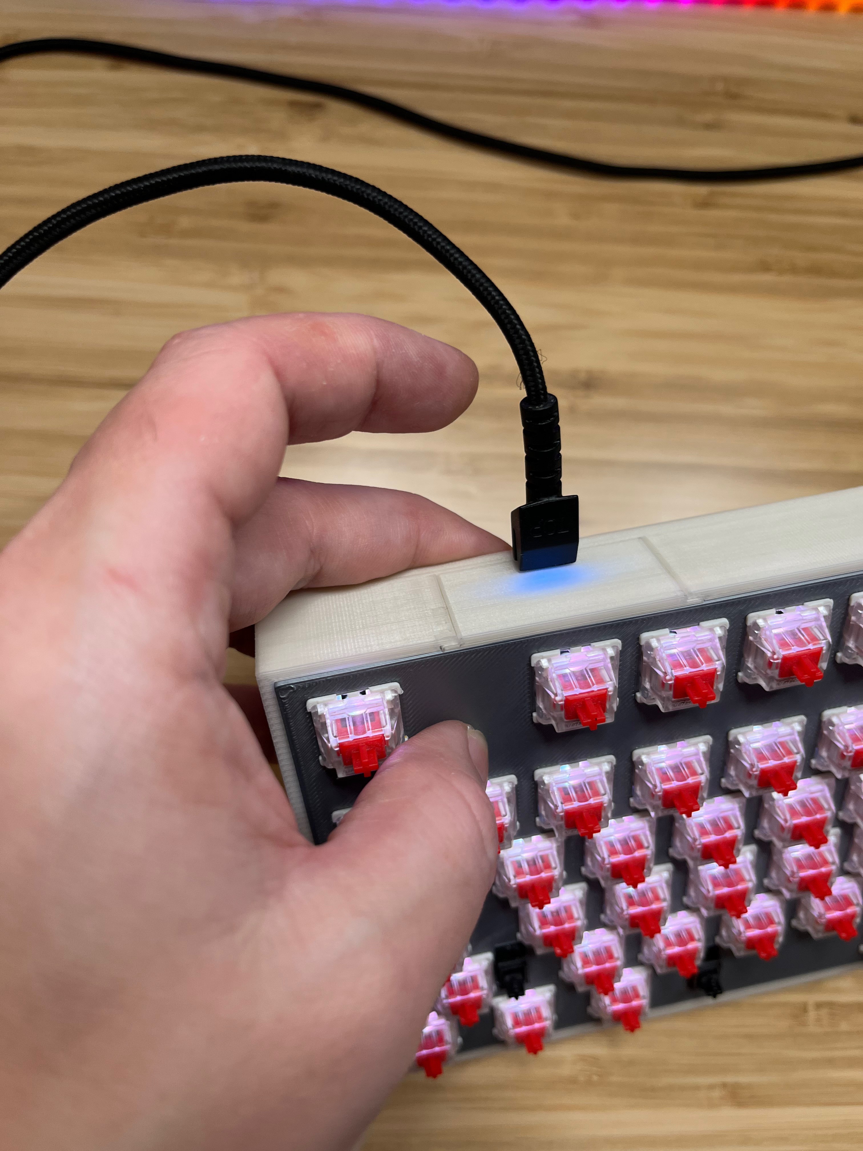
It wasn't great, but I still had at least some PCB into which I could put the switches. So I searched for solution I can fix the problem and realised I can just solder wires and attach IO expanders externally. Was it pretty? Hell no. Did it work? Flawlessly ... 😃
So this was it. Moment my keyboard wrote its first words ...
One of problems I hit was how to add microcontroller to PCB. It's possible, but actually eventually I realised I don't want to do that.
I believe that having microcontroller outside has its own benefits like modularity and upgradability (for newer version of Bluetooth, different USB connector, more powerfull microcontroller, etc.).
Due to that board has just 4 PIN connector for I2C interface.

Case
⏱ 2 months
Yep, you guessed it. This is a time I bought my new 3D printer. 🤩
I had finally working PCB, meaning I had dimensions and I could start designing case and keeping in mind, that eventually I want to have it from aluminium.
Goal was simple. I need a case:
- I can put my PCB into
- It needs to fit battery
- It needs to fit microcontroller
- Needs to allow to easily exchange connector for connecting the keyboard (upgradability) or ideally whole microcontroller attachment.
Dimensions are clear how to solve, exchange of connector was trickier but eventually I came up with solution that case is actually composed of 4 parts:
- Frame - Main block holding PCB and all components inside.
- Microcontroller Holder - Small piece holding microcontroller which can be pushed into frame. As this block holds the connector and it's separate module, it ensures upgradibility.
- Plate - Part holding switches together.
- Cover - Top part of frame improving holding of keyboard plate and covering space between keycaps and switch base.
Modeling the case was quite straightforward, I had to iterate through couple of prototypes to:
- Learn how to print with 3D printer accurately.
- Polish dimensions.
- Solve how to print model bigger than printer 😃
Second iteration
Proof of concept was done, back to the original goal. I wanted RGB LEDs, right? That send me back to KiCad.
RGB
⏱ 2 months
Remember when I mentioned that I need to connect 87 switches? Well for each of them I needed LED and only ordinal LED, but RGB LED. Each RGB LED requires 4 wires (one per R/G/B channel and one for common pin) - 348 wires in total.
Wiring of switches teached me the trick with the matrix. I minized it to just 3x6 + 17 wires, which needs to be connected somehow to microcontroller. Somehow turned out to be through LED driver - another chip behaving kind of similar like IO expander but meant for driving LEDs.
LED drivers helps to solve LED specific problems like:
- Current limitation.
- Offloading driving LEDs from power hungry microcontroller to dedicated chip with low power consumption.
- It might have pre-built effects and animations.
- It provides logic for gama correction, brightness settings, addressing, etc.
- And mainly, it allows to control all those wires through some low wire count interface (in my case I2C as I was using chip IS31FL3743A).
This was the moment I realised how tiny the keyboard is. Sure, it looks big, but did you ever noticed all those holes in it? Yep, you cannot get wires through them and you need plenty of wires there with some minimal distance from each other! 😃
Common problems:
- What LED driver should I use?
- Where can I buy this and that LED driver? Where it is on stock?
- Will this LED driver be compatible with these LEDs?
- What LEDs should I use?
- What will be the power consumption of LEDs?
- Will USB manage to power LEDs?
- Will battery survive reasonable time powering up those LEDs?
- I am able to find battery of reasonable size and capacity fitting the case?
- etc.
Firmware
⏱ 1 month
I eventually switched to my custom firmware from QMK. I still do plan to support QMK eventually (and it should be fairly easy to add support), but custom firmware allowed me faster iterations as I could drop learning on QMK internals which might be quite complex.
Especially if you experiments with multiple microcontrollers - like those which are not yet supported by QMK like Arduino Portenta H7.
You might think that this is overkill for keyboard and you would be right. I am targeting cheaper microcontrollers as primary microcontrollers but I am also wondering if I can offer more with better microcontrollers ... 😃
I am currently playing with these ideas in a keyboard:
- REST API - wouldn't it be cool hooking keyboard to some events? Like you keyboard blinking a specific key when you receive a message somewhere?
- Machine learning - would it be usable for power consumption optimization? Or maybe some typo detection?
- Plugins - wouldn't it be cool to have user friendly way to put pluggins into keyboard running directly on a keyboard and modifying its beahviour? (one idea is password manager like 1Password - or any other - which would allow you to have all passwords available where you have your keyboard... - don't go into details on security, but of course protected)
- ...
Manufacturing
⏱ 1 month
I fixed also missing pull ups and finally send my second iteration for manufacturing.
For previous iteration I let jlcpcb build just PCBs and solder everything myself as I was trying to save the cost, but this was no longer an option for current iteration.
LEDs I chose were tiny (1.6 x 1.6 mm) and they were 87. Considering I just learn basics of soldering I knew something would went wrong. 😛 So I let jlcpcb do also assembly of components.
Jlcpcb at that time could solder components only from single side of PCB. That affected design.
Jlcpcb did not have LED drivers I needed at that time, so I had to solder those 5x5 mm with 40 pads by hand. This was quite experience and cannot imagine I would do it without microscope.
When I had new iteration of PCB ready, I plugged it in and guess what? LEDs worked, but IO expanders were still dead. It took some time, but eventually find the problem:
VSS x VDD - You could think S like a source and D like a drain like me and you'd be wrong. Yep, I swapped ground and voltage wires on IO expanders when doing recent changes. So what now?
Solution was surprisingly simple. I just scratched two paths on a PCB with scalpel and bridged it with two wires between connector and IO expanders.

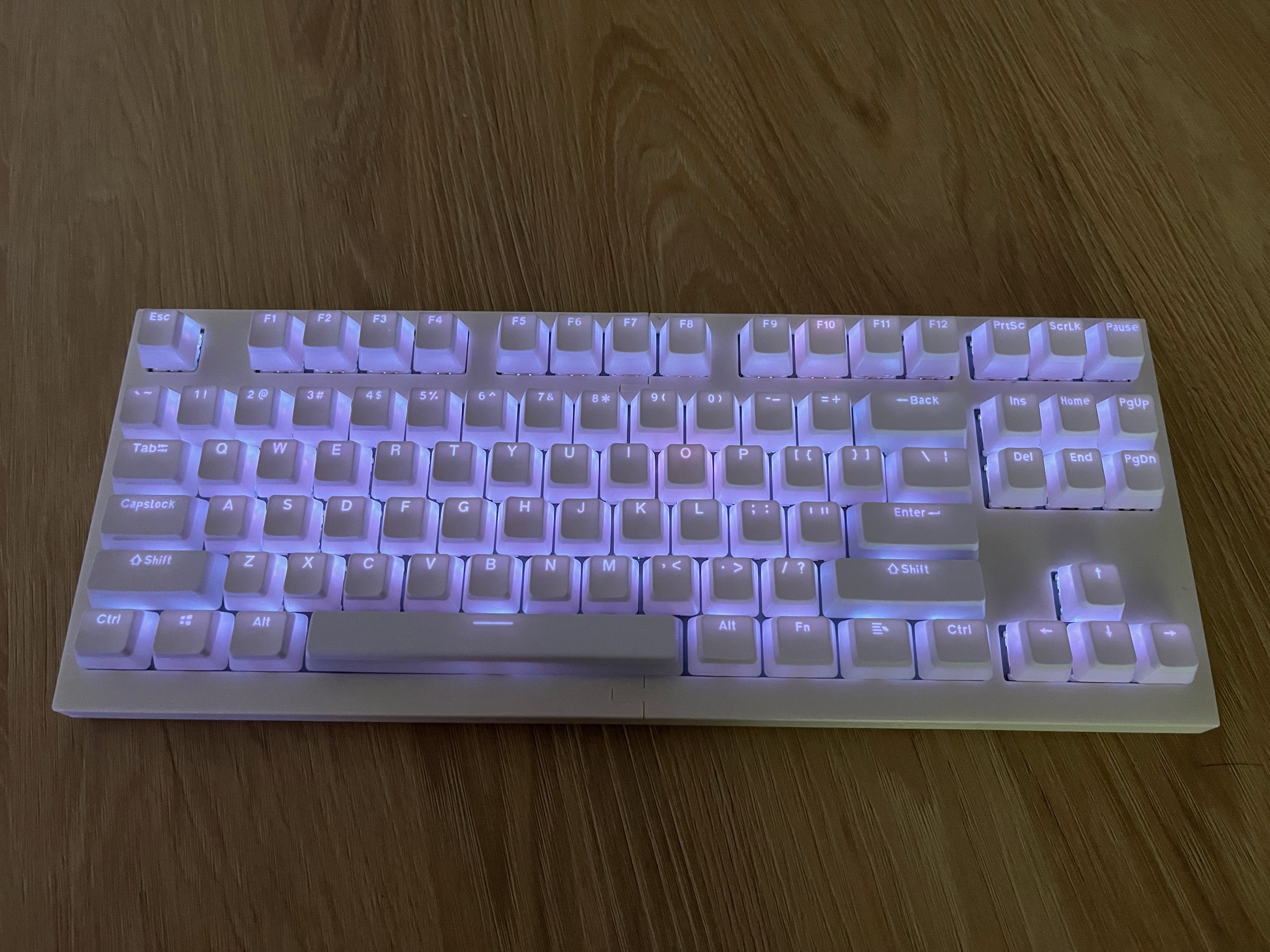
Third iteration
At this moment I had fully working RGB keyboard. Thou testing it I discovered few hickups 😃
Numpad
⏱ 2 months
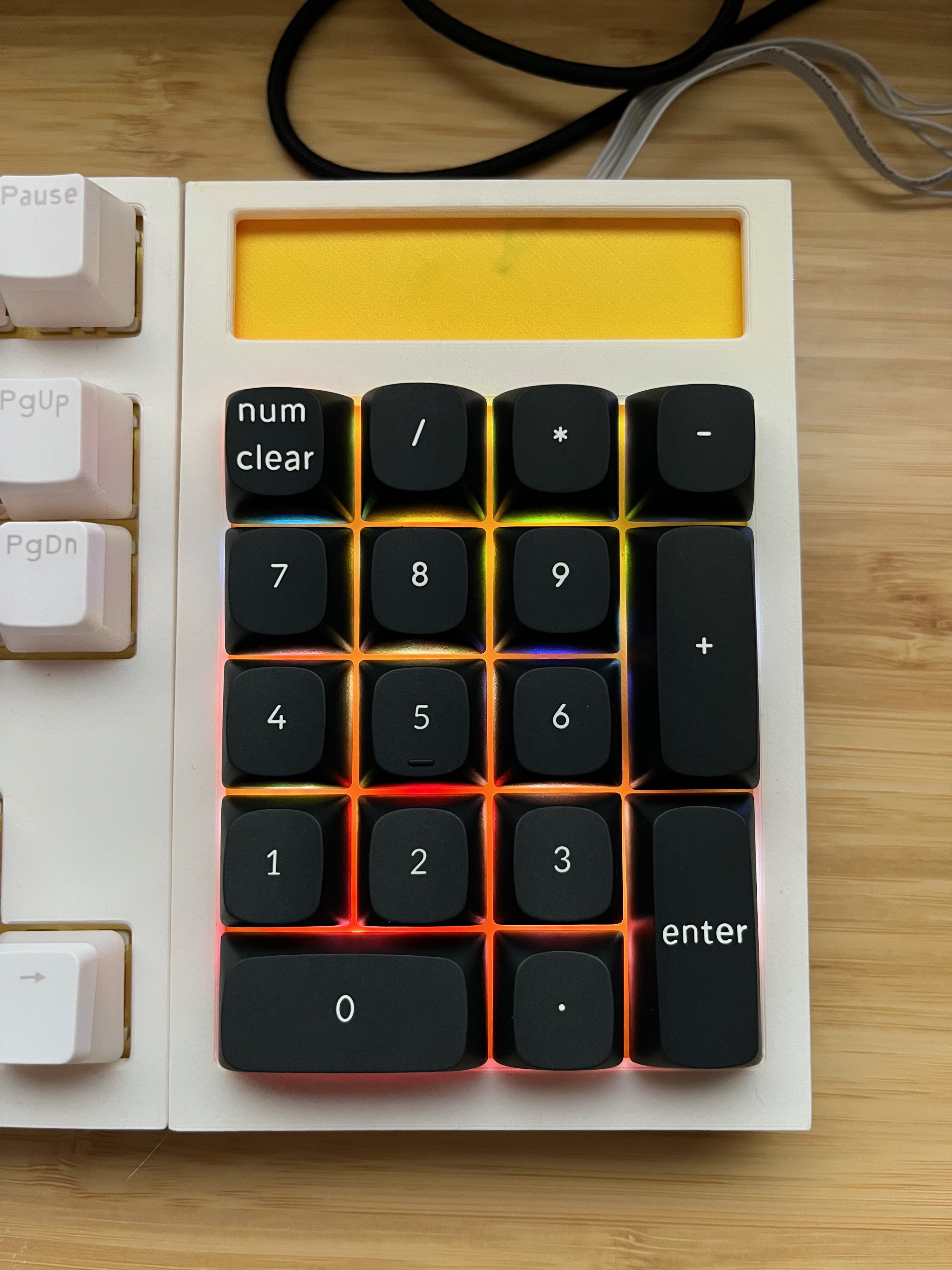
I got actually several requests on numpad and considering it has very similar design I decided that it should be easy to provide it and it would make my iterations cheaper as I could test everything on smaller PCBs...
So I designed it and also added small improvement!
Magnetically attachable numpad. What I can uncover for now is, that this iteration supports attaching numpad magnetically on both sides of keyboard.
I'll go into details on this feature in some future article.
Brightness
⏱ 1 month
First problem was brightness. It turned out, that LED drivers could provide only 20 mA per row while each LED on a row could be power up with 20 mA. They just didn't have enough of power to be bright as much as I wished.
How to solve this? Simple solution turned out to be to just use more LED driver chips. Originally I had just 2 chips on 17 columns, new design is counting with max 2 columns per chip.
This simple change is making LEDs very bright and it looks goergeous! 😍
Tiny problem is heat. LED driver chips are actually heating whole PCB that much, that you cannot hold your hand on it when LEDs are on max ... 😄 Luckily it was enough to glue tiny heatsink on them and everything is fine now 😃
Latency
⏱ 2 months
I2C running on 400 KHz turned out to be an issue for keyboard latency. As keyboard needed two IO expanders which cannot be communicated with in parallel it takes time. E2E latency of keyboard is around 16 ms.
This is very well usable for ordinal scenarios, but it's far from gaming keyboards (~1 ms).
There are at least couple of solutions which could be implemented:
- Run I2C on higher frequency You need either all I2C devices running on same frequency or you need multiple I2C channels. Second option is not available for cheaper microcontrollers and first option is scifi considering what LED driver and IO expander chips are on market.
- Use SPI IO expanders running on SPI can be found and they can support even 24 pins, which eliminate need for 2 IO expanders on a board. And it gets even better as SPI can run on higher frequency. Dis-benefit is that it requires more wires.
I decided to go with SPI and chip Max7301ATL+ and that's where I got stucked for very long time... (2 months!!)
Stuck on Max7301ATL+
What was the problem? Well I managed to connect to the chip, send it data but chip replied occassionally correct non-senses.
At first, I wasn't sure about the order of bytes as it wasn't clear to me from datasheet, so I rather tried all variants. I tried also several open source libraries which claimed to be working, but nothing really worked and that was the point that I realised I need to see what is actually happening on wires...
I found that either I can go with osciloscope or logic analyzer. Considering I am focus mostly on digital signals, I focused on analyzers.
Eventually decided to go with Saleae Logic Analyzer - it can show analog signals, recognize signals up to 100 MHz, etc.
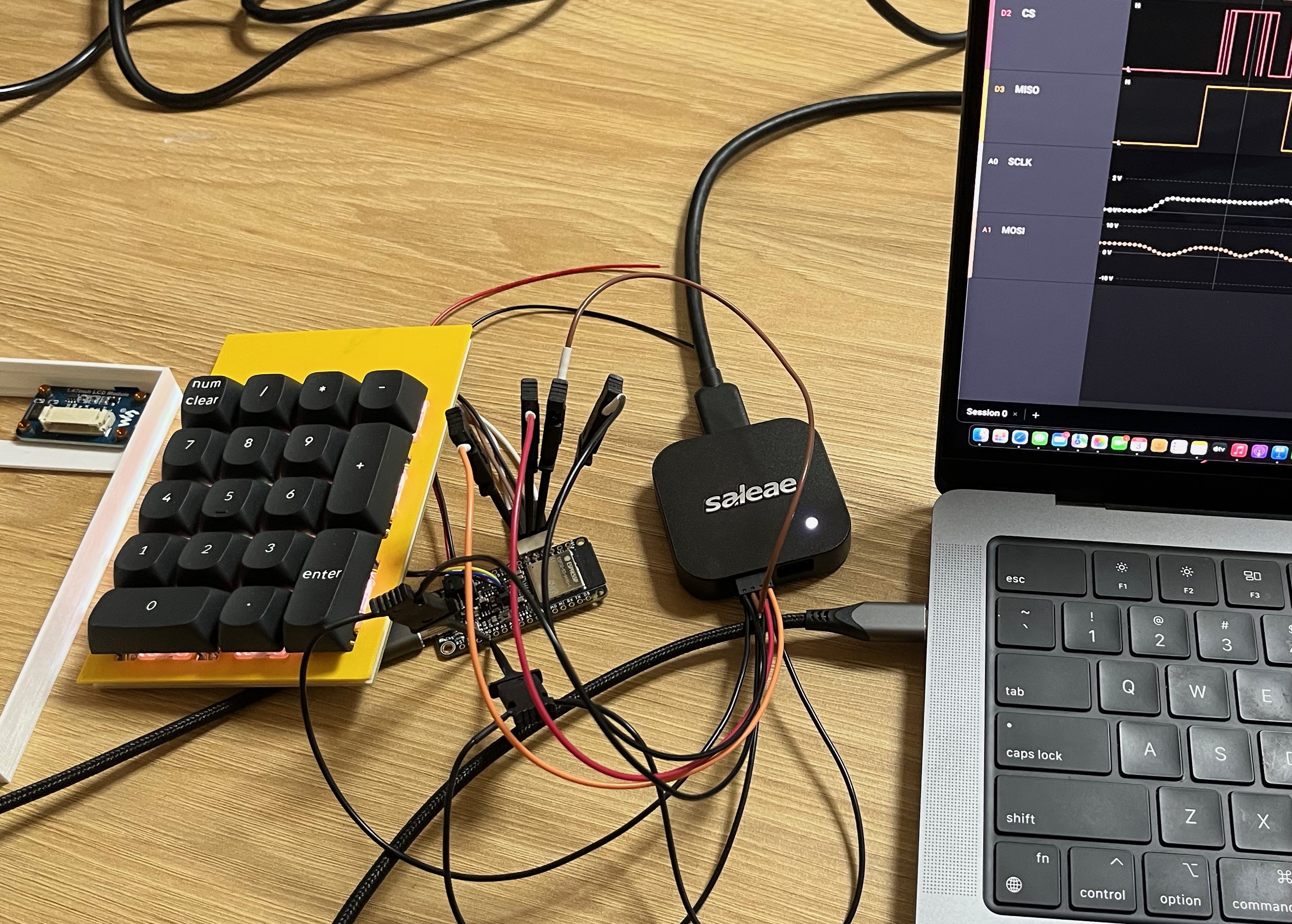
I start up the software (btw love it!), realised I had few issues in what I am sending into a chip and fixed them - thanks here to Maxim Integrated, their support helped me even thou I am just hobbyist and I don't sell it.
Eventually ending up with this state:
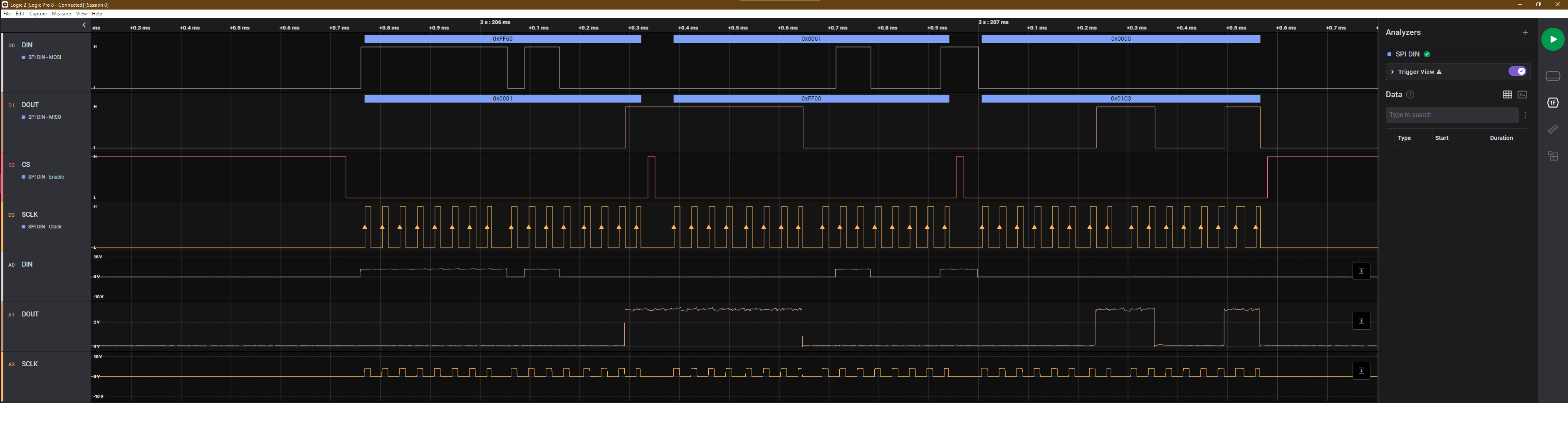
Everything was just correct except of MISO signal which was giving me still non-senses. So what to do? I took a break for few weeks to clear my head and when I got back I immediately notice something strange. Logic Analyzer was showing me, that some signals are around 4 V, which was quite surprising considering it should had been powered up by 3.3V...
Whole problem was that I was using Arduino Micro which was running on 5 V from USB and all signals were generated also on 5 V range, but chip was powered up by 3.3 V as it was connected to 3.3 reference voltage pin 🤦🏼♂️.
So I connected the PCB to different micro controller running fully on 3.3V and what happened? It worked! 😃
Next steps
At this point I am finally happy with what I have, new PCB for TKL keyboard is on the way from JLCPCB and I am preparing case for CNC manufacturing. Is it the end? Well no.
More upgrades are comming in the future:
- Finger print sensor
- Display on Numpad
- Plugins for firmware
- Magnetically attachable accessories
- Gyroscope or waking up the keyboard
- Wireless charging
- ...
Follow my project and make sure you'll not miss it! 😉
Discussions
Become a Hackaday.io Member
Create an account to leave a comment. Already have an account? Log In.