 Addepalli Dolendra Vikas
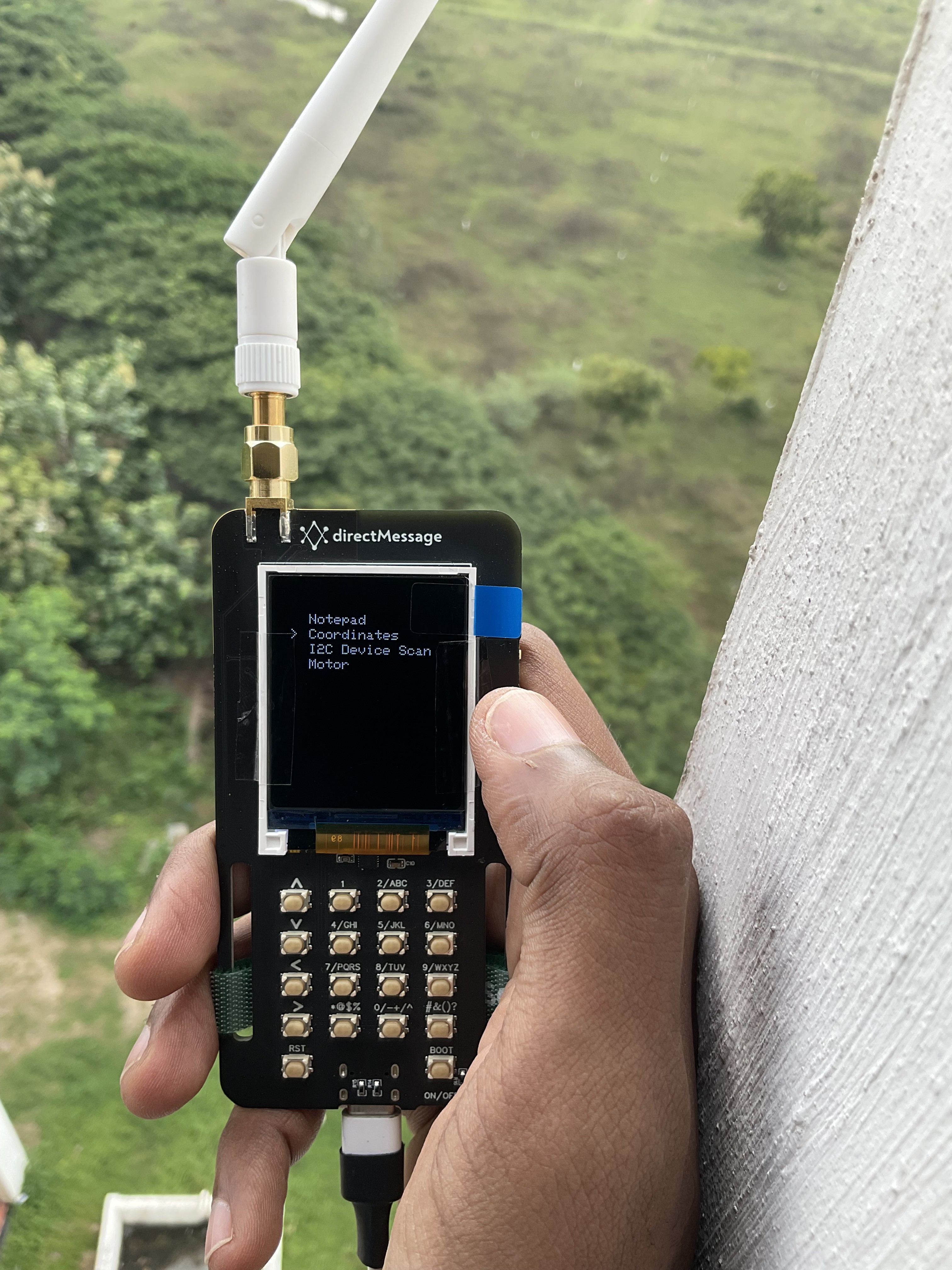
directMessage
A custom-designed hardware that establishes secure communication with identical devices through a dedicated 865MHz (EU868/US915/AU915/KR920/IN865) channel, utilizing the Lora E5 SOC (Wio-E5) from Seeed Studios.
I would like to express my gratitude to Seeed Studio for generously sponsoring the PCB fabrication and component assembly for the project, as well as to Amanda Sun, for her invaluable assistance in securing this sponsorship.

Motivation
In the interconnected world of the 21st century, where the internet has become ubiquitous, privacy seems like an elusive concept. Maintaining private communications with your friends without involving network service providers or unwanted third parties has become increasingly challenging. But what if there was a way to establish a secure communication channel that even the most prying eyes couldn't predict? Welcome to the retro-inspired solution: directMessage.
With directMessage, you can say goodbye to privacy concerns. This innovative device enables you to communicate securely, free from the interference of unwanted third parties. It's like having a two-way pager but with advanced features that take communication to a whole new level. Picture live navigation and seamless sharing of location, altitude, and attitude.
The magic of the directMessage lies in its ability to establish a communication channel that remains hidden from prying eyes. This means that even those with malicious intent won't be able to predict the frequency you're using to communicate. Say hello to a world where secure communication is within your grasp.
While the concept may feel reminiscent of the past, the directMessage is equipped with cutting-edge technology that ensures its effectiveness. Although it boasts advanced features, its range is optimized for shorter distances, typically spanning just a few hundred meters.
2D view of the directMessage

Hardware Features
Following are the Hardware features of the first version of the directMessage (from now on referred to as "dM").
MCU

‘directMessage’ is equipped with a LoRa E5 SoC, also known as Wio-E5. The SoC uses ST system-level package chip STM32WLE5JC, embedded high-performance LoRa chip SX126X.
Display
The user interface of the dM features a 1.8" LCD (ST7735) that communicates with the Lora E5 MCU via the SPI communication protocol.
Vibration Motor
A haptic feedback sensation is generated for the user using an 85mA Cylindrical DC motor (Vibration motor).

Control the motor with PB9 and PB14 GPIOs, accessible through solder pads, as shown in the figure. Connect the center pad (Gate terminal of the driving MOSFET) with either GPIO (PB9 or PB14) to gain motor control.
Location
The dM uses the POT GPS module (Quectel L80) to acquire the user's location, with significantly low power consumption (around 20mA) during acquisition and tracking. Its quick reacquisition time of less than 1 second enables rapid user action response.

The 'Wio-E5' module has only one UART port (PB6, PB7), so the RX and TX pins are made accessible to the controller via a DIP switch. When the switches on the DIP are in the 'ON' state, the GPS module will take control of the UART bus. If the switches are in the other state, the UART bus control will be taken over by the onboard USB to TTL converter.
LoRa Chatting
Enable a peer-to-peer local communication channel for LoRa chatting using the LoRa P2P feature.

Four GPIOs (PB4, PA3, PA2, PB10) are multiplexed over the other four GPIOs (PB3, PB5, PC1, PC0) to control 16 switches, creating four arrows and 12 Numpad keys.
USB Type-C

The dM is equipped with a Type-C interface, enabling battery charging and device debugging via UART. The onboard USB to TTL converter, SiliconLab's 'CP2102,' connects the RX and TX pins of the TTL converter to the 'PB6' and 'PB7' of the controller. (make sure that the switches of the DIP switch are positioned in the appropriate mode as discussed in the Location section to use the USB as a debugger).
Altitude
To measure altitude and humidity, a pressure sensor (BME280) is employed, operating on the I2C protocol.

The address to this slave has two options (0x77 or 0x76). The slave address can be set by soldering two adjacent pads accordingly.
Attitude and Compas
A 9DOF IMU (MPU280) positioned below the display measures the device's orientation and compass direction (relative to the earth's north and south pole).

Solder two adjacent pads to set the IMU slave address to 0x68 or 0x69. The SCL and SDA pins of the IMU are connected to the PA15 and PB15 of the controller.

Peripherals

The left-side connector facilitates the connection of external sensors via the I2C protocol. The right-side connectors provide access to the UART bus and the 'SWDIO' and 'SWCLK' pins for programming the controller.
Ensure correct polarity when powering the device with a 3.7V nominal voltage cell using a 2-pin JST connector.
Programming
Program the dM using the 'ST-Link V2' programmer through the 'SWDIO' and 'SWCLK' pins. Remember to short the ground of the host computer and the device. Power the device with either the battery or the USB during programming.
Check out the repo for the design files and keep track of the latest version of the directMessage. Stay tuned for further updates from the side of the software.
Thank you :)


Discussions
Become a Hackaday.io Member
Create an account to leave a comment. Already have an account? Log In.