 Joy
JoyWeb:www.bitfoic.com
Overview
National Semiconductor created the LM3914 integrated circuit (IC) in the late 1970s for usage in displays that graphically represent an analog signal's magnitude. On its outputs, it can power up to 10 LEDs, LCDs, or vacuum fluorescent displays. The device can be used, for instance, as a voltmeter thanks to the linear scaling of the output thresholds. With additional LM3914 ICs connected in series, the scale can be expanded from the default configuration of ten steps to over 100 segments.
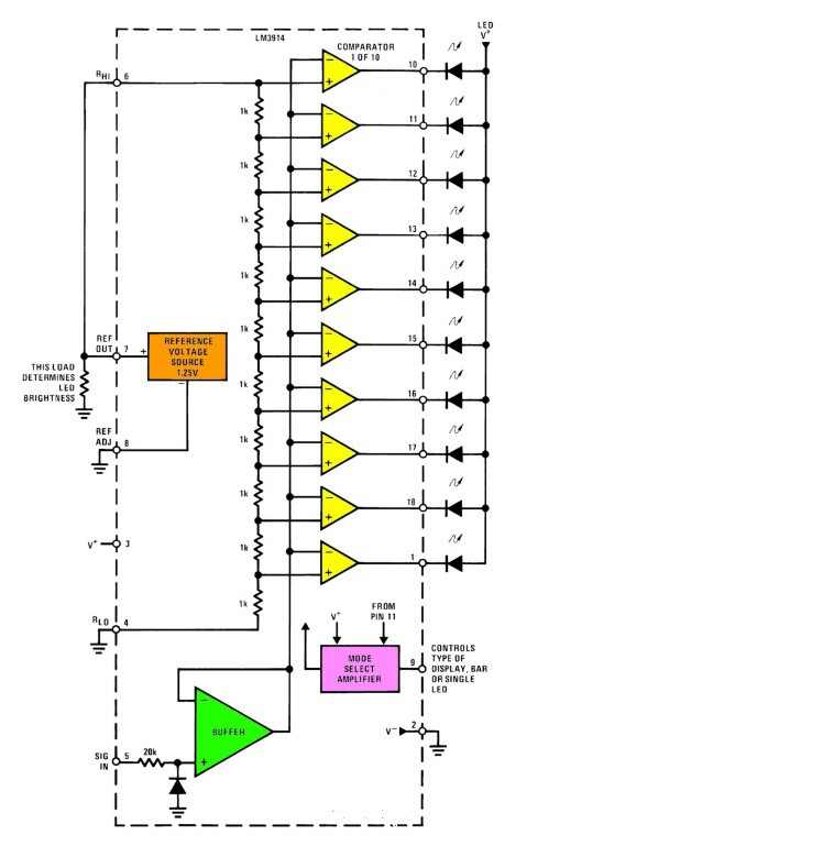
Applying the LM3914 as part of an analog meter circuit is quite simple. In addition to the 10 display LEDs, a 1.2V full-scale meter only needs one resistor and a single 3V to 15V supply. The LED brightness control is created when the first resistor is a pot. This really straightforward external circuitry is shown in the simplified block diagram.
Pin Configuration
They have 3 siblings, LM3914, LM3915, and LM3916. The shape is the same. But the main difference is that the LM3914 displays a linear scale. LM3915 displays Log scale and LM3916 displays in Semi Log scale. Which we will learn in the next opportunity.
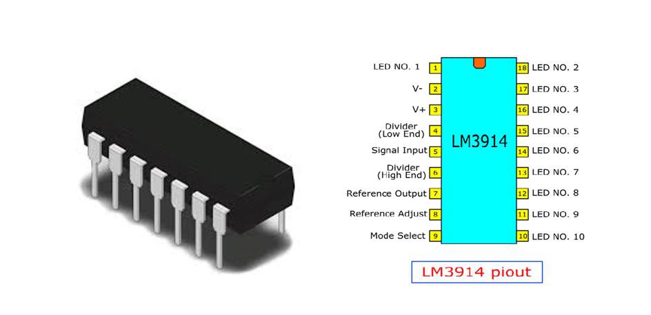
- Pin1: (LED1, LED2, LED3,..LED10): The LED which has to be operated is allied to these pins
- Pin2: (V- or Ground): GND pin of the integrated circuit
- Pin3: (V+ or Vcc): Supply voltage ranges from 3V to 18V
- Pin4: (RLO): Low-level voltage used for potential divider
- Pin5: (Signal): Input pin analog signal based on which the LED is controlled.
- Pin6: (RHI): High-level voltage used for potential divider
- Pin7: (Ref Out): Reference voltage of Output for limiting the LED current
- Pin8: (Ref Adj): Adjust pin used for voltage reference
- Pin9: (Mode): Choose among Dot or Bar Mode
Features for the LM3914
- Drives LEDs, LCDs or Vacuum Fluorescents
- Bar or Dot Display Mode Externally Selectable by User
- Expandable to Displays of 100 Steps
- Internal Voltage Reference from 1.2V to 12V
- Operates with Single Supply of Less than 3V
- Inputs Operate Down to Ground
- Output Current Programmable from 2 mA to 30 mA
- No Multiplex Switching or Interaction Between Outputs
- Input Withstands ±35V without Damage or False Outputs
- LED Driver Outputs are Current Regulated, Open-collectors
- Outputs can Interface with TTL or CMOS Logic
- The Internal 10-step Divider is Floating and can be Referenced to a Wide Range of Voltages
Applications of LM3914 IC
The LM3914 IC can be used to build electronic projects that include the following.
- Battery Meter for Robot
- Monitoring of 12V Car Battery
- Tester Circuit for Soil Moisture
- Monitoring of Lead Acid Battery Charger
- Charge Monitoring Circuit for Atmospheric
- Kitchen Exhaust Fan for Controlling Temperature
- Meter Circuit for Temperature
- Digital gauges
- Electronic displays
- Low-cost monitor devices
- Crude Battery level indicators
- Fade bars
LM3914 Replacement
LM3914 Equivalent LED Driver: LM3916, LM3915
Alternative LED Driver IC’s: CD4511, MAX7219, CD4054
Datasheet
LM3914 Datasheet
Basic LM3914 Block Diagram
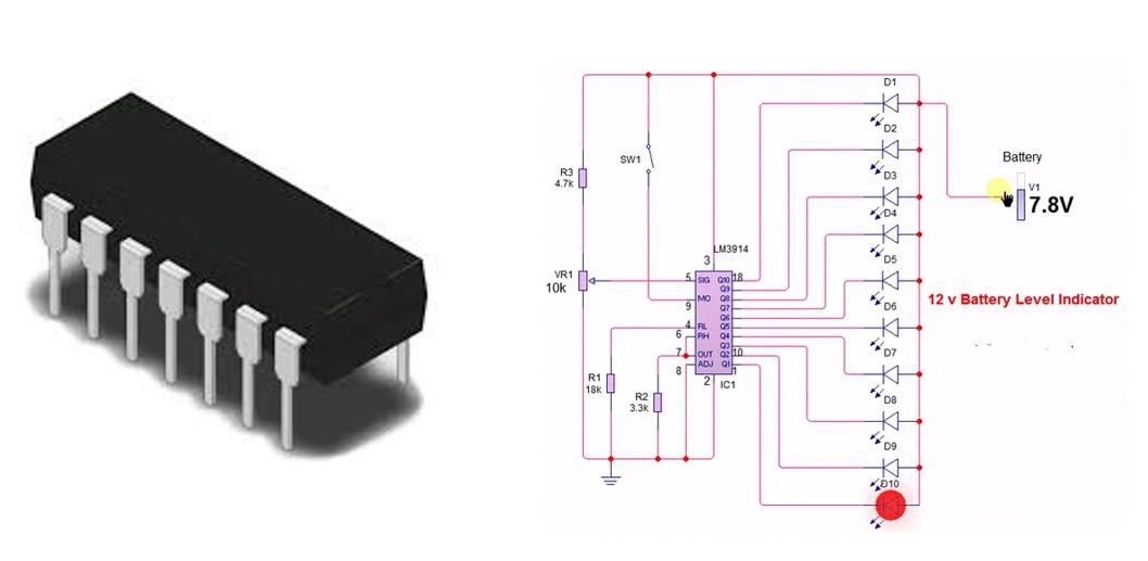
How to test 12V Battery with IC LM3914?
This 12-volt battery charge monitor circuit displays the charging of a normal 12-volt automobile battery using colored LEDs. After the circuit is constructed, some last-minute modifications with a digital multimeter are required to ensure proper operation. observe: direct current voltage measurement (DC).
We employ the LM3914 integrated circuit to accomplish our objective. An analog voltage meter that can manage up to 10 different LEDs is the LM3914. By connecting the integrated circuit's pin 9 to VCC or 0 volts, the integrated circuit's pin 9 of these LEDs can be switched between "bar mode" and "point mode" of display.
The LM3914 is made to compare the strength of an electrical signal to a predetermined reference voltage value and show the result.
Battery Charge Monitor Operation and Adjustment
Put 12.65 volts between the circuit's positive and negative terminals.
LED 10 must turn on before the potentiometer (VR) can be adjusted.
Once the voltage is gradually reduced, the additional LEDs will begin to light up one at a time until you reach LED1.
There will be a voltage of roughly 11.85 V between the circuit terminals when only LED1 is on.
A fully charged battery has a voltage of 12.65 volts or higher, whereas a depleted battery has a value of 11.85 volts or less.
The battery charge is greater than 50% when LEDs 8, 9, or 10 are illuminated.
When LEDs 4, 5, 6 or 7 are on they indicate that the charge is between 30 and 50%.
When LEDs 1, 2 or 3 are lit, they indicate that the battery charge is less than 30%.
This circuit consumes less than 10 mA, as long as the “point mode” is chosen. Which means that only one LED lights up at a time. If the “bar mode” is used, the current consumption is higher.
By altering the value of resistor R3, the LEDs' illumination intensity can be altered. The brightness of the LEDs lowers and the current usage falls as the value of resistor R3 is raised.
To avoid a connection with reverse polarity, use diode D1.
Circuit component list
1 LM3914 integrated circuit (IC1)
1 1N4007 semiconductor diode (D1)
1 150K resistor (R1)
1 18K resistor (R2)
1 5.6K resistor (R3)
1 56K resistor (R4)
1 10K potentiometer (VR)
1 47 uF / 16V capacitor (C1)
1 0.1 uF (microfarads) capacitor (C2)
3 red LEDs
4 yellow / amber LEDs
3 green LEDs
Discussions
Become a Hackaday.io Member
Create an account to leave a comment. Already have an account? Log In.