 Low Cost Circuits
This article describes a cheap Medium Frequency (MF) amplifier made from two BF173 transistors. The medium frequency range is from 300 kHz to 3 MHz.
BF173 transistors are silicon radio frequency transistors. "B" means silicon transistor and "F" is for radio frequency. If the first two letters are AF then that means that the transistor is germanium radio frequency, not silicon radio frequency.
The circuit was tested to work at 1.5 V. However, that does not mean that you can connect this circuit to a 1.5 V battery. This circuit needs a high current power source to prevent a possible power supply oscillation.
Step 1: Design the Circuit
I omitted any power supply filtering to reduce the cost of the circuit:

I used low-value Rc resistors (Rc1 and Rc2) to reduce the effect of transistor stray capacitance on amplifier bandwidth. I considered using feedback bias instead of fixed bias because feedback bias transistor amplifiers have a wider bandwidth. However, feedback bias significantly reduces the gain of the amplifier. Because I cannot measure the frequency response of this amplifier above 3 MHz due to my low-cost equipment limitations I decided that the amplifier does not need to have a wide bandwidth.
The input resistance of the transistor needs to be equal to the output resistance of the amplifier. Otherwise, you are also amplifying the noise. However, matching the input and output resistances of transistor amplifiers is beyond the scope of this article. However, with approximations, this problem can be simplified. The input resistance of a fixed bias transistor amplifier is equal to:
Ri = (Beta*re)||Rb
= Beta*re*Rb/(Beta*re + Rb)
Where: Beta = Transistor Current Gain
re = 0.026/Ie
= 0.026*Beta/(Ic*(Beta+1))
Ic = Biased Collector Current = Vs/2/Rc
Rb = (Vs - 0.7 V) / (Ic / Beta)
You let Ri = Rc and solve the equation for Vs.
You can also assume that:
Ri = Beta*re
and
re = 0.026/Ic
because Rb is often a lot greater than Beta*re and thus can be ignored. Collector current Ic approximately equals to Ie. Therefore:
Rc = Beta*0.026/Ic
= Beta*0.026/(Vs/2/Rc)
= Beta*0.026*2*Rc/Vs
Vs = 0.052*Beta
Thus to match the input and output resistance you need to adjust the power supply.
Step 2: Simulations
I used PSpice student edition version 9.1 to simulate my circuit:

Simulations show that the amplifier has a wide frequency response:

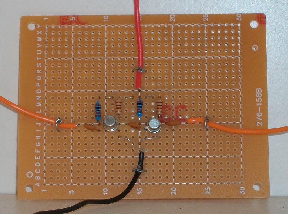
Step 3: Make the Circuit
Testing showed that to bias the transistor collector-emitter voltage at half supply Rb needs to be 10 kohms, not 18 kohms as was predicted in the results. This is because PSpice model parameters are for the general-purpose 2N2222 transistor, not BF173. BF173 component is not available in the software.

Step 4: Testing
I used a Hantek 6022BE USB Oscilloscope to test my circuit.
I set the frequency of my Dick Smith Electronics FG-30 signal generator to 3 MHz. I connected the channel 1 oscilloscope lead to the signal generator and the second to transistor output Vc1 (collector-emitter voltage):

The gain is 1 V / 250 mV = 4.
Thus the total gain of the amplifier is 16.
When I tried connecting the lead to the second transistor output (collector-emitter voltage) I found that the output was saturating even at the minimum amplitude setting of the signal generator. Thus I connected a 10 kohm resistor in series with amplifier input to attenuate the input and prevent output signal saturation.
I set the input frequency to 300 kHz and got the following output with the attenuator:

I increased the input frequency to 1 MHz and got the following output with the attenuator:

I increased the input frequency to 3 MHz and got the following output with the attenuator:

The gain is 1 with an attenuator. Without an attenuator, it would be a lot higher.
Later I tried measuring the transfer characteristic (X = amplifier input and Y = amplifier output) of the amplifier at different frequencies:
300 kHz:

1 MHz:

3 MHz:

Conclusion
Testing showed that the amplifier had a such high gain that I could not measure the gain because the output was saturating. I was seeing a square wave in my oscilloscope plots.
The gain of the first transistor could be more than 4 because the even first plot (where only one transistor was used to amplify the input signal) also shows saturation.
Discussions
Become a Hackaday.io Member
Create an account to leave a comment. Already have an account? Log In.