 teardownit
How does one determine the direction and strength of the current of the probing signal? What does the information about the current of probing and induced signals provide? Which techniques allow the most accurate determination of the cable's depth? How does one take the influence that induced signals have on neighboring cables into account?
Complex locator models don't necessarily just have receivers with different types of sensors, but can also have receivers with several sensors of the same type. For example, two horizontally-oriented inductive sensors (two coils) provide a great deal of extremely useful information with the help of signal processing, which considerably facilitates the tracing process. In this case, the information refers to the power of the probing signal current, its direction in the cable being traced, and the depth of the cable. Also, all these additional functions are only used for tracing in active mode, or when the line signal is fed from the signal generator.
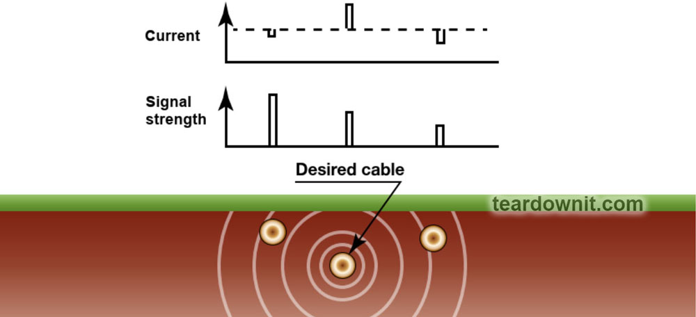
The necessary cable can be easily identified among other nearby cables that also carry the induced signal if the direction of the current and its power can be determined. This is possible because the direction of the carrier current and the induced current always oppose one another (the signal current flows from the transmitter and the induced current flows to the transmitter). Additionally, the signal current in the cable being traced is always more powerful than the induced currents in neighboring cables.
The ability to determine the power and direction of the current allows you to confidently identify underground cables that run in parallel but at different depths. The carrier signal that the receiver detects from a deeply buried cable being traced is often significantly less powerful than the induced signal from a cable that runs at a shallower depth.
Aside from this, determining the current strength allows you to detect taps and assess the condition of the cable insulation. The current value gradually drops due to signal leakage to ground as it moves along the cable being traced. If the value changes intermittently, this signifies a tapped cable or a defect in the insulation. The detection of a second signal source with the same current direction (from the generator) indicates a tap. Other cases of intermittent signals indicate an insulation defect.
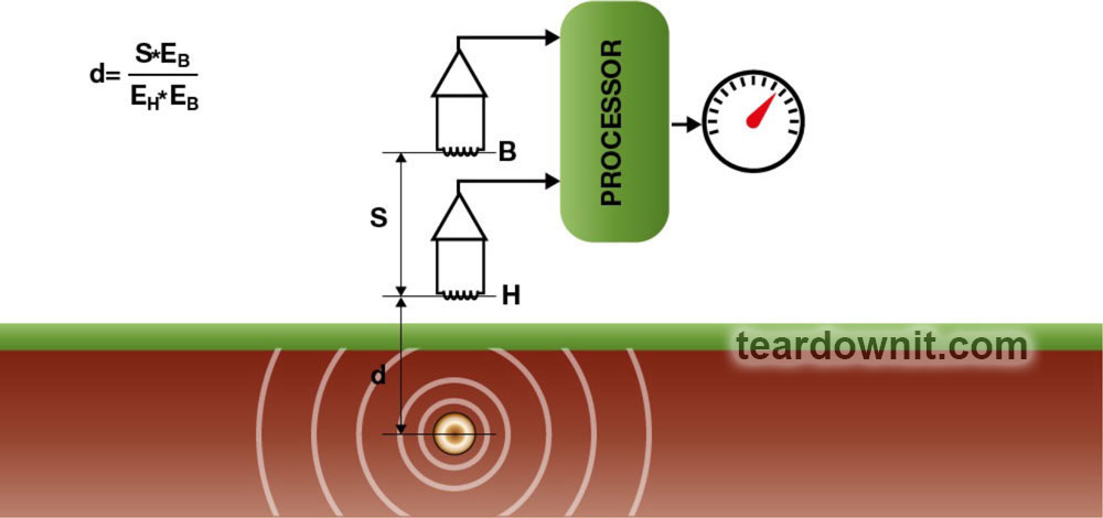
If repair work is being carried out in high-density conditions, where multiple communications are nearby, it is very important to perform cable tracing with a receiver. A cable receiver can estimate the depth of all the lines that pass in the vicinity with high accuracy. A device with two coils does this with the help of internal mathematical processing of two signals, which it receives from two sensors (the sensors are located at different heights inside the device). The amplitude of the induced signal depends on the distance to the source, so the depth can be calculated using a simple formula.
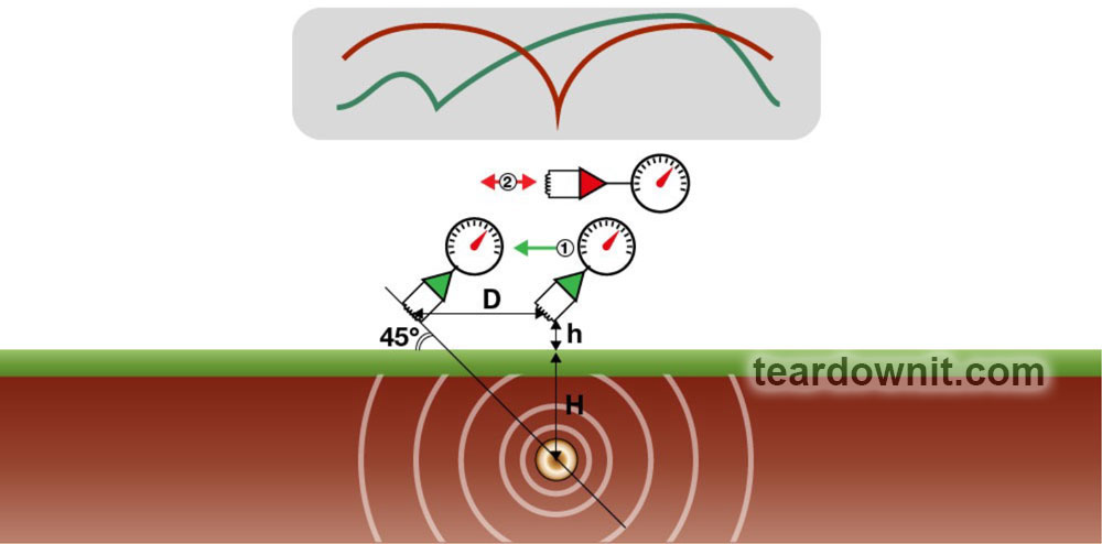
However, the same result can be achieved even when using a receiver with a single inductive sensor. The following simple algorithm can be used to do this:
- Make a mark directly above the cable on the ground (using the peak or zero value of the received signal);
- Turn the sensor at a 45° angle relative to the ground and, while maintaining this angle, slowly move it away from the cable being traced;
- The signal volume will decrease to a minimum and then increase again;
- It's necessary to mark the point at which the signal level was at its minimal;
- The depth of the cable will be equal to the distance between the two points marked on the ground.
However, magnetic field lines can be distorted by other conductors nearby. The first sign that this is the case is a change in the location of the maximum or minimum signal when the coil sensor is at different heights. An imaginary line passing through certain points indicates the more likely position of the cable. The exact position can be determined after assessing the cable's depth. The measurements will be different if the field is distorted and measurements were taken from different sides of the cable being traced. The most accurate value can be calculated as the arithmetic average of these values.

It is necessary to repeat the measurements in order to verify your findings. The sensor should be raised above the ground to a certain height (about 20") and the figures obtained should differ by this specific value.

It is important to note that depth measurements are always made to the longitudinal axis of the cable being traced. If the cable has a small diameter, there's no cause for concern. However, if you are measuring a pipeline with a large diameter, you need to be very careful because the distance from its top point to the ground will be less than the obtained value.
Keep in mind that the margin of error may be higher near places where the cable bends and branches. Therefore, it is better to perform measurements at a distance of at least 13-15 ft from such places. This also applies when working near the location where the signal from the inductive antenna is applied since the receiver can pick up the transmitter signal directly. A "safe" distance for measurements in such cases is at least 80-100 ft away.
Discussions
Become a Hackaday.io Member
Create an account to leave a comment. Already have an account? Log In.